

patent · US4547147A
Combustion device for a car
15 October 1985
Text
Page 1bibliographic recordscan →
United States Patent (19)
Suzuki et al.
54 COMBUSTION DEVICE FOR A CAR
75 Inventors: Hiroyoshi Suzuki, Himeji; Shoichi Washino, Suita, both of Japan Assignee: Mitsubishi Denki Kabushiki Kaisha, Tokyo, Japan
Foreign Application Priority Data Jun. 30, 1983 JP Japan ............................... 58-120838 Int. Cl. ................................................ F23Q 3/00
58. Field of Search ........................ 431/264, 265, 351
2,221,519 11/1940 Jones et al. ......................... 431/265 3,223,136 12/1965 Mutchler ..... ... 431/265 3,733,169 5/1973 Lefebvre ......... ... 431/265
ALX
OTHER PUBLICATIONS
"Diesel Particulate Trap Regeneration Techniques',
"Thermal and Catalytic Regeneration of Diesel Partic ulate Traps', W. R. Wade, et al., SAE Paper No.
Primary Examiner-Carroll B. Dority, Jr.
Attorney, Agent, or Firm-Oblon, Fisher, Spivak, McClelland & Maier
A combustion device for a car comprises a fuel-atomiz ing nozzle for atomizing and injecting fuel, a combus tion tube extending along said nozzle in the direction of injection of fuel, a coaxial airstream supplying passage extending along the outer circumference of said fuel atomizing nozzle, an orifice means for fuel mixture formed near the inlet of said combustion tube and at the lower side of said fuel-atomizing nozzle, an ignition plug placed between said orifice means and said fuel atomizing nozzle, and a lower airstream supplying pas sage which has at least one aperture opened to said combustion tube and is placed below said fuel-atomiz ing nozzle.
5 Claims, 5 Drawing Figures
Drawings
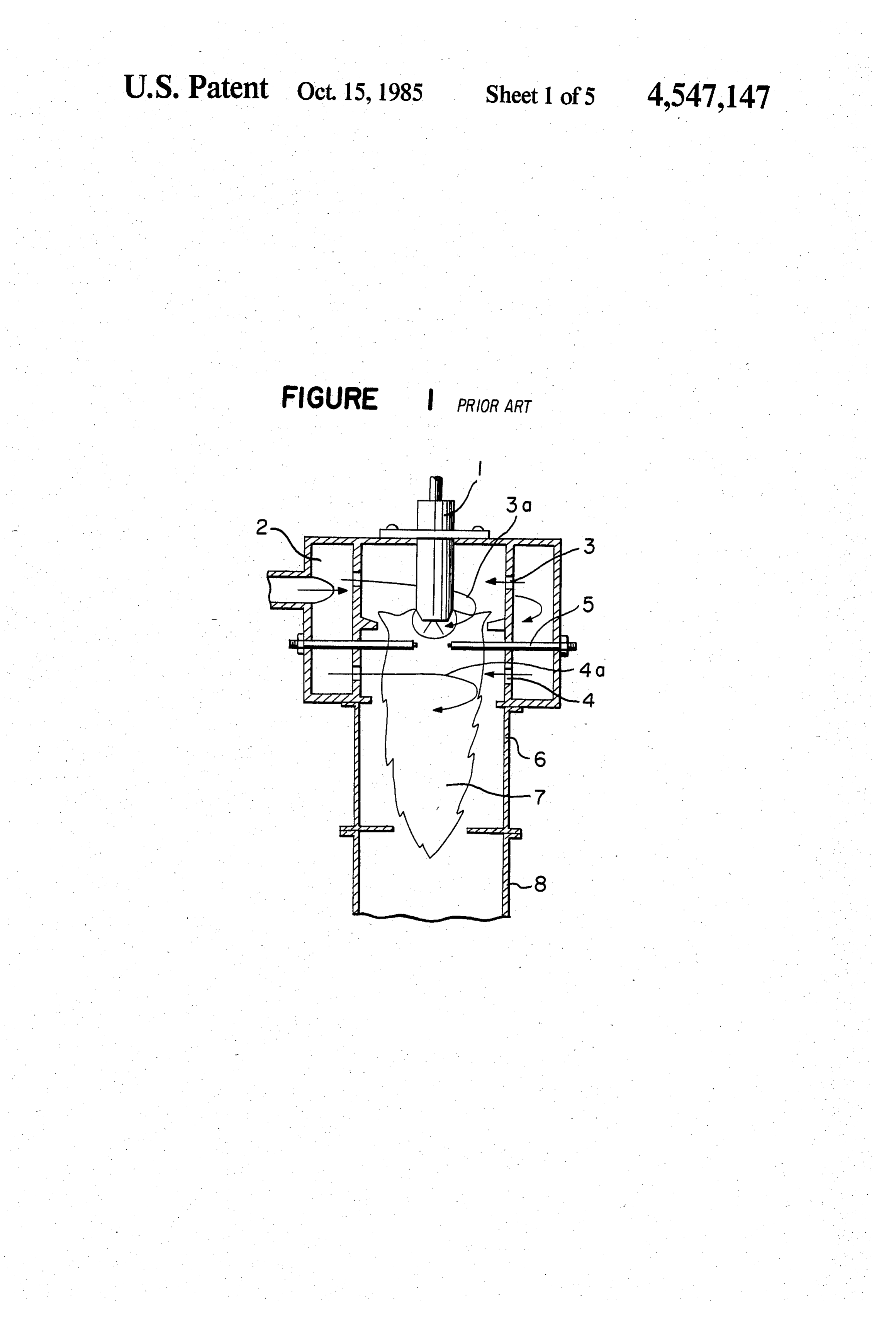
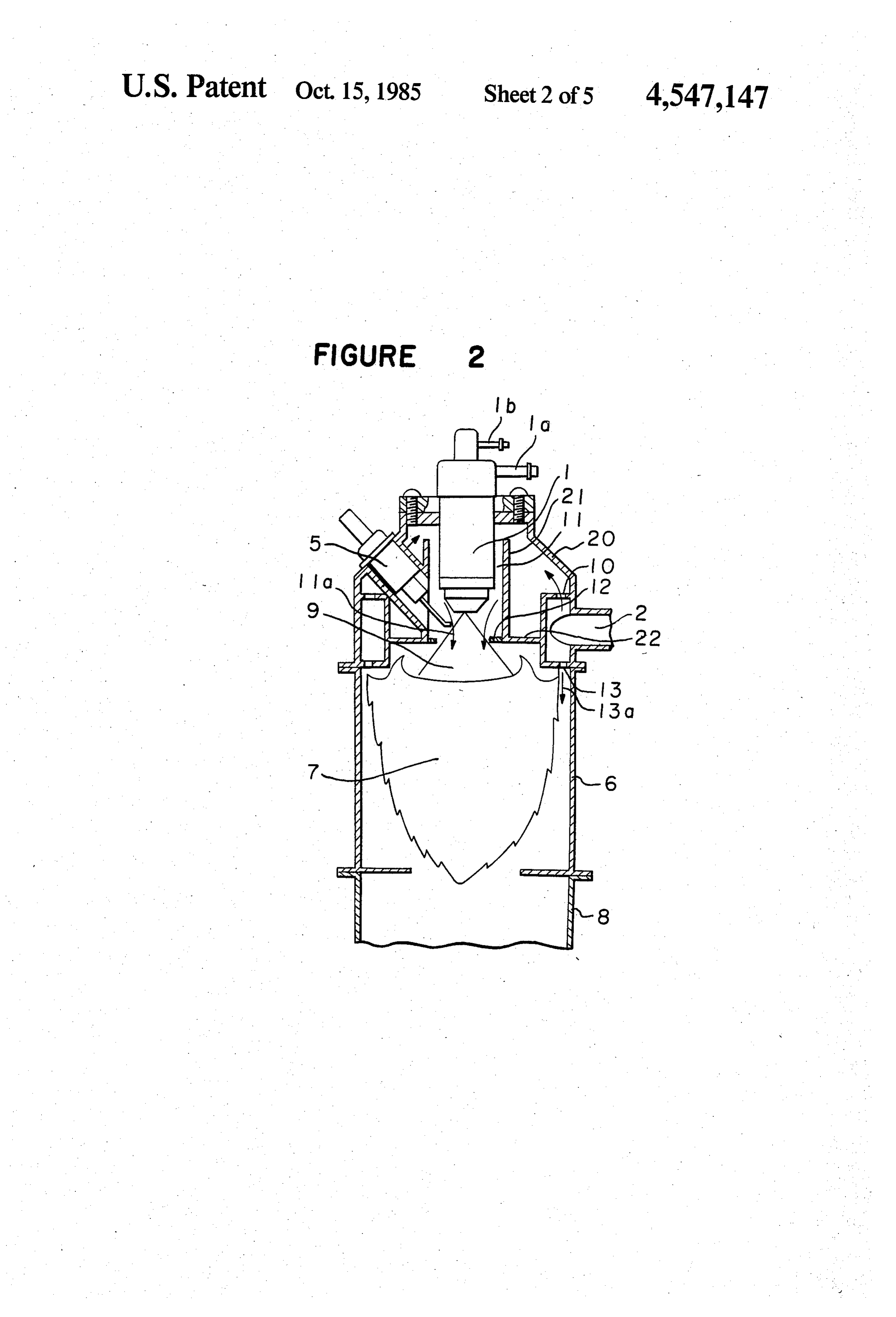
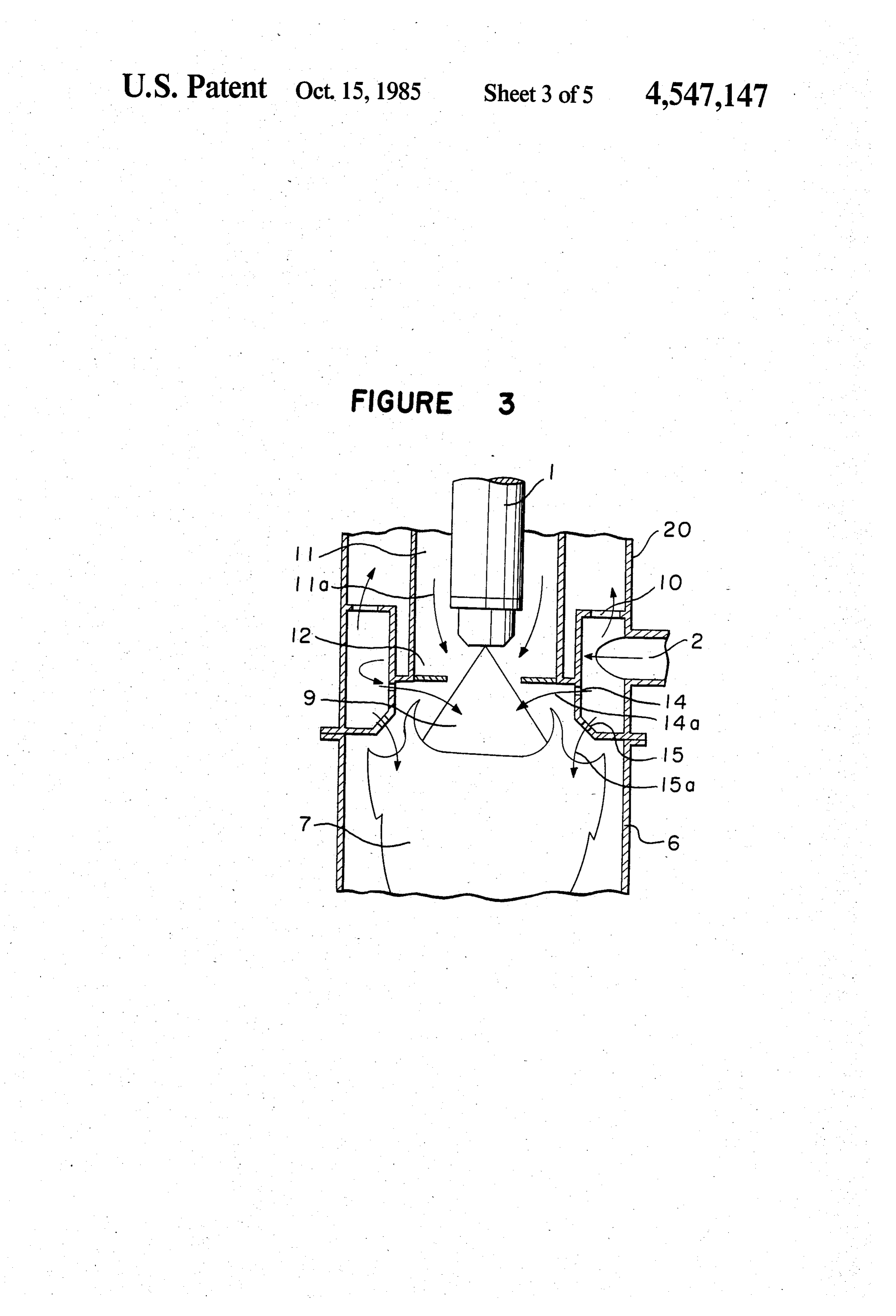
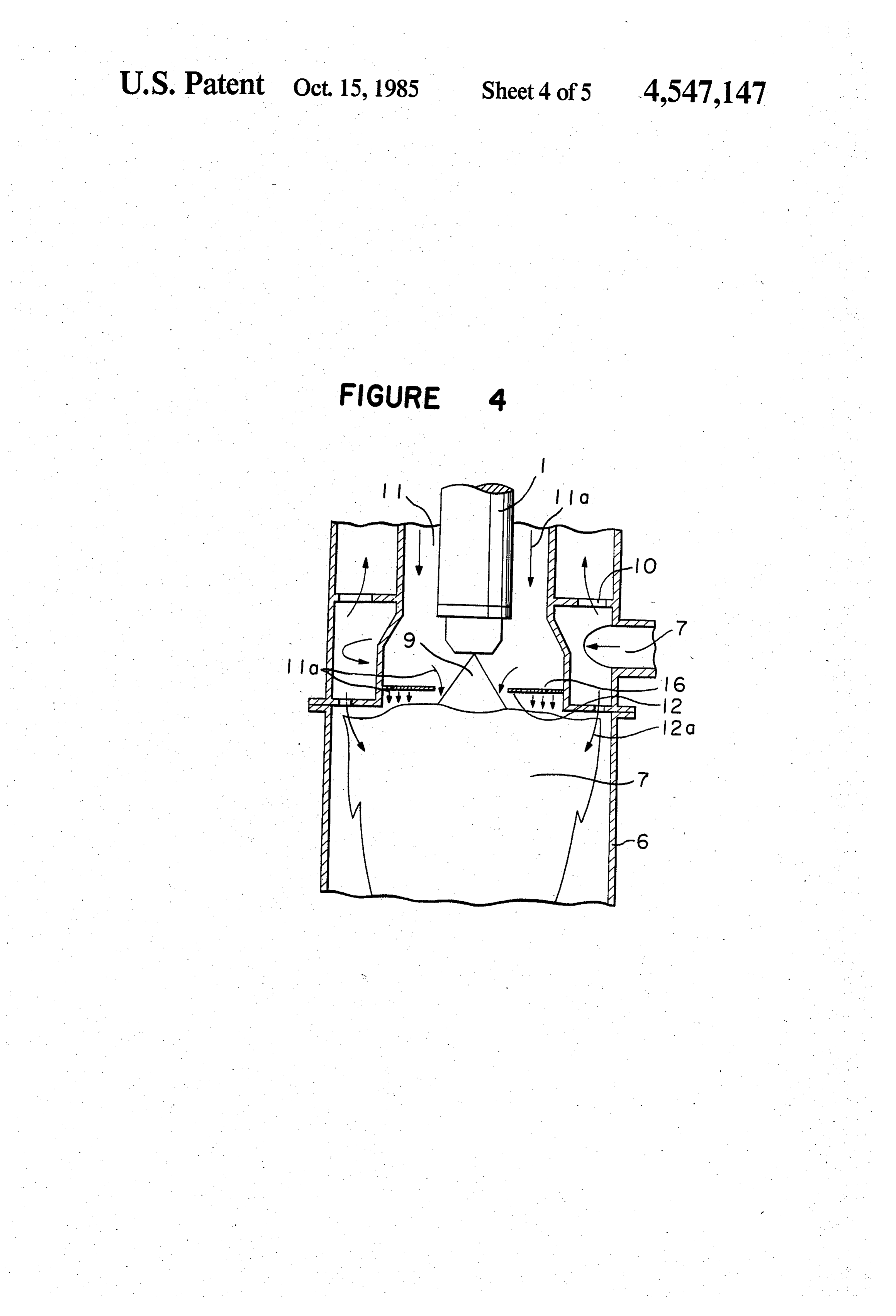
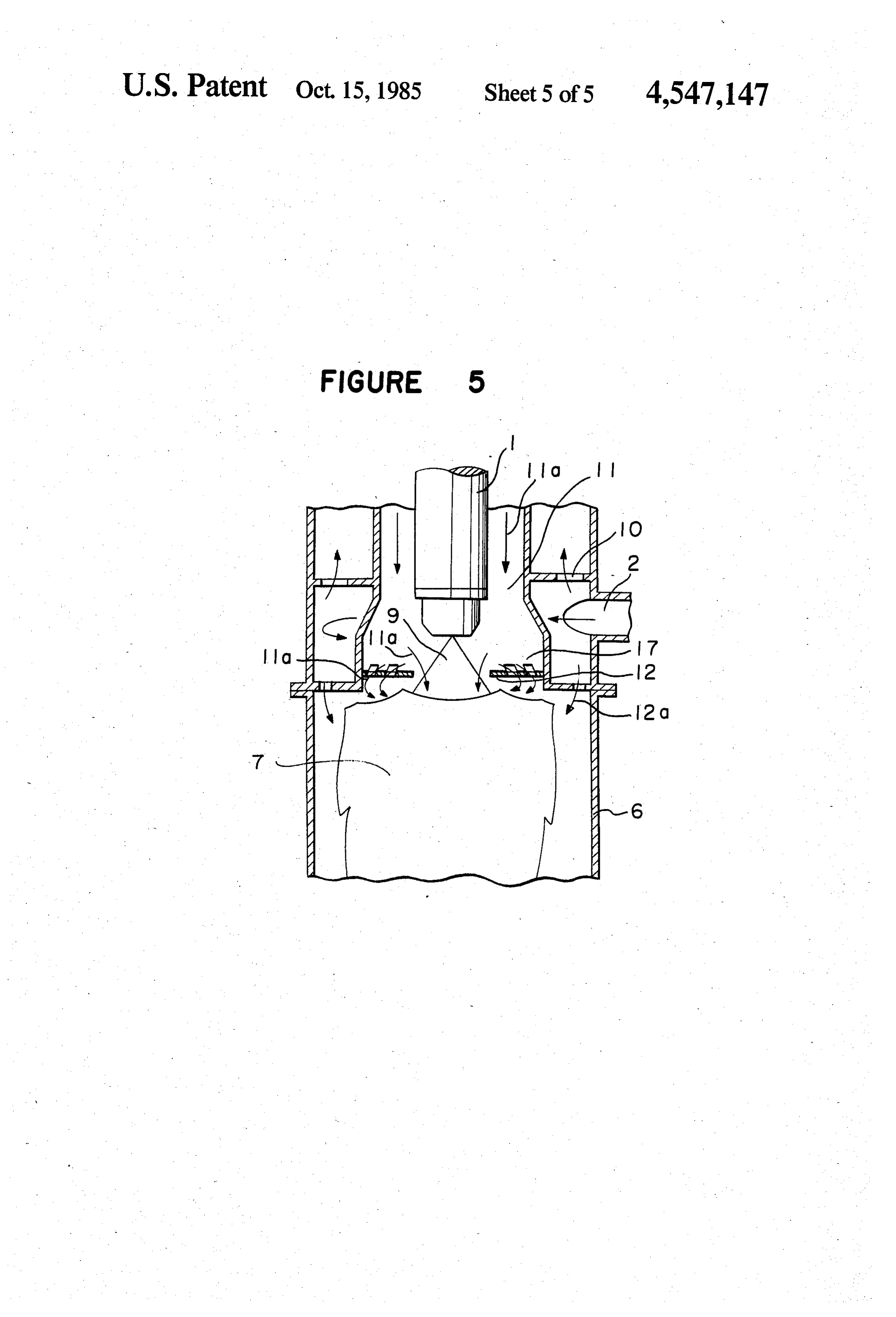
FIG. 1 is a sectional view showing an example of a assureschanges;
Page 2drawing sheetscan →
Page 3drawing sheetscan →
Page 4drawing sheetscan →
Page 5drawing sheetscan →
Page 6drawing sheetscan →
Page 7scan →
stabilized ignition surface by forming whirling-air
COMBUSTON DEVICE FOR A CAR streams, there takes place the drawback as follows. Since a force acts on the flame 7 in the directions of its
BACKGROUND OF THE INVENTION center axis and the nozzle, the ignition surface is pro The present invention relates to an exhaust gas puri duced at a position very close to the nozzle and the fying device for a diesel engine. More particularly, it upper whirling-air 3a causes a part of the flame 7 to relates to a combustion device such as a regenerative contact with the nozzle to thereby deposit soot on the burner for a car which performs heating, burning and nozzle surface. Further, there takes place a temperature removing fine particles, in exhaust gas, deposited on a 10 rise in the nozzle surface by thermal transmission and filter to eliminate the clogging of the filter. thermal radiation from the flame to thereby cause the The particles contained in exhaust gas discharged fuel, from cars such as diesel engines are harmful to a human surfaceremaining non-burned, deposited on the nozzle body and lawful restrictions on the amount offine parti the accumulation ofThe to form tar.
the contamination of the nozzle by soot, tar and other materials cles dishcarged from the diesel engines have been con 5 rapidly changes the area of the ejection opening of the sidered or executed in many countries. nozzle and in the extreme case, the ejection opening Various measures have been proposed to reduce the amount of discharged fine particles. An effective way is, may be clogged. Thus, in the conventional regenerative for example, placing a filter in the exhausting system of burner, it has been difficult to obtain a stable combus a diesel engine to catch fine particles thereon and then 20 tion through its life time due to, especially, occurence of the filter is heated by a high temperature combustion the vapor lock of fuel in the nozzle which is caused by gas ejected from a regenerative burner to burn the fine the temperature rise in the nozzle. particles deposited on the filter, thereafter they are SUMMARY OF THE INVENTION removed.
Problems imposed on the regenerative burner is that It is an object of the present invention is to provide an reliable, instant ignition should be attained as well as 25 improved combustion device for a car to eliminate the stable combustion and a satisfied combustion under a disadvantages of the conventional device. high burden should be attained in addition to miniatur It is another object of the present invention to pro ization required for restriction of car space even under vide a combustion device equipped with a small-sized conditions of broad change in temperature and vibra regenerative burner suitable for installing in a car which tion load which are inherent in a car. 30
FIG. 1 is a sectional view showing an example of a assureschanges;
instant firing even though the ratio of fuel to air reduces contamination by the deposition of conventional regenerative burner in which the refer soot and tar ence numeral 1 designates a high pressure atomizing term use andonprovides a nozzle, ignition plugs and so on in long a stable combustion.
type or a twin fluid atomizing type nozzle, the numeral 2 refers to a whirling air supplying passage, the numeral 35 The foregoing and the other objects of the present 3 indicates upper whirling-air apertures, the numeral 3a invention have been attained by providing a combustion denotes upper whirling-air fed from the apertures 3, the device for a car which comprises a fuel-atomizing noz numeral 4 designates lower whirling-air apertures, the zle for atomizing and injecting fuel, a combustion tube numeral 4a indicates lower whirling-air fed from the extending along the nozzle in the direction of injection apertures 4, the numeral 5 indicates a pair of ignition 40 of fuel, a coaxial airstream supplying passage extending plugs, the numeral 6 represents a combustion tube, the along the outer circumference of the fuel-atomizing numeral 7 refers to flame produced by firing atomized nozzle, an orifice means for fuel mixture formed near fuel and the numeral 8 denotes a part of an exhaust pipe the inlet of the combustion tube and at the lower side of system of an engine. the fuel-atomizing nozzle, an ignition plug placed be In the device having the construction as above-men 45 tween the orifice means and the fuel-atomizing nozzle, tioned, fuel or a primary fuel mixture atomized and and a lower airstream supplying passage which has at ejected from the nozzle 1 is mixed with the upper whirl least one aperture opened to the combustion tube and is ing-air 3a fed through the upper whirling-air apertures placed below the fuel-atomizing nozzle. 3, then is fired by means of the ignition plugs 5 to form the flame 7 in the combustion tube 6through the agency 50 BRIEF DESCRIPTION OF THE DRAWINGS of the lower whirling-air 4a fed from the lower whirl A more complete appreciation of the invention and ing-air apertures, and thereafter combustion gas is led to many of the attendant advantages thereof will be a filter through the exhaust pipe 8. readily obtained as the same becomes better understood The structure of the regenerative burner, however, by reference to the following detailed description when has disadvantages of wearing of electrodes because the 55 considered in connection with the accompanying draw ignition plugs are always in contact with the flame 7 and of causing deterioration in firing property due to con ings, wherein:
tamination of the ignition plugs with soot, tar and so on. FIG. 1 is a longitudinally cross-sectional view of the There are further disadvantages that since the growth conventional combustion device for a car; of the core of flame produced by firing is inhibited due FIG. 2 is a longitudinally cross-sectional view of an to the cooling function of whirling-air which disturbs embodiment of the combustion device for a car of the ambience around the electrodes of the ignition plugs 5, present invention;
time required for totally firing, namely delay time in FIG. 3 is a enlarged longitudinally cross-sectional firing is prolonged and variation in the delay time of view of another embodiment of the combustion device firing when the ratio of fuel to air is changed is also 65 of the present invention;
large. FIGS. 4 and 5 are respectively enlarged longitudi In the burner having the construction as above-men nally cross-sectioinal views showing the other embodi tioned, although an attempt has been made to obtain a ments of the present invention.
Page 8scan →
DETAILED DESCRIPTION OF THE flame accompanies a circulating stream formed by the PREFERRED EMBODIMENTS upper and lower airstreams at the peripheral portion at the downstream side and in addition, the ignition sur
Several embodiments of the present invention will be face is separated from the orifice 12 by suitably selecting described with reference to drawings. 5 the ratio of the speed of the lower airstream to the upper FIG. 2 is a longitudinally corss-sectional view of an airstream. Accordingly, the flame 7 is not in contact embodiment of the present invention in which a twin with the nozzle 1, the ignition plug 5 and so on to mini fluid type nozzle is used as a fuel-atomizing nozzle. In mize contamination of these parts with the soot and tar. FIG. 2, the atomizing nozzle is provided with an air Further, since the electrode of the ignition plug 5 feeding pipe 1a and a fuel feeding pipe 1b to inject a 10 does not contact to the atomized fuel mixture stream stream of atomized fuel-air mixture 9. The atomizing and the nozzle 1 and ignition plug 5 is cooled by the nozzle 1 is surrounded by a casing 20 in which a whirl upper coaxial airstream 11a, a temperature rise in the ing-air supplying passage 2 is formed. There is formed nozzle is small, contamination of these parts with soot at least one upper air-supplying aperture 10 which is and tar is prevented and the wearing of the electrode is communicated with the whirling-air supplying passage 15 small whereby ignition property and stable combustion 2 to direct air upwardly in the casing 20. A cylindrical property are not impaired.
wall 21 with both ends opened extends along the nozzle In the regenerative burner of the present invention, 1 with a gap therebetween to form an upper coaxial the bluish core of the flame in the atomized fuel mixture airstream supplying passage 11 so that air blown from stream produced by firing by means of the ignition plug the upper air-supplying aperture 10 flows downwardly 20 5 is not inhibited in its growth by virtue of the upper through the passage 11. Air flowing through the upper airstream 11a as a coaxial air flow. Further, drawbacks coaxial airstream supplying passage 11 is designated by such as generation of white smoke at the initiation of the reference numeral 11a. The lower end of the cylin combustion as the result of the inner portion of the drical wall 21 is connected to the casing 20 through a burner being wet due to delay in ignition, acceleration horizontal annular wall 22. An orifice 12 for fuel mix- 25 of formation of tar and the discharge of fuel without ture is provided below the cylindrical wall 21 near the burned to the outside are eliminated because the air-fuel inlet of a combustion tube 6. The orifice 12 has an inner mixture possess instant ignition property in a broad diameter sufficient to throttle the air from the upstream range from 1 to 2 in the fuel-air ratio. side but not to cause the impingement of the atomized Further, in the structure of the burner of the present fuel mixture 9 on it. A lower coaxial airstream supply- 30 invention, the position of the ignition surface of the ing passage 13 is formed by at least one aperture which flame 7 is substantially determined by the flow rates of is communicated with the whirling-air supplying pas the atomized fuel mixture stream 9 and the upper coax sage 2 and which opens in the combustion tube 6 at the ial airstream 11a whereby it is possible to feed the lower downstream side of the orifice 12. A lower coaxial coaxial airstream in conformity with the shape of the airstream blown from the passage 13 is designates by the 35 combustion tube 6 which is subjected to restriction for numeral 13a. The electrode of the ignition plug 5 is mounting in a car.
placed near the atomized fuel mixture 9 and between In the first embodiment of the present invention, the the atomizing nozzle 1 and the orifice 12 so as not to flow rate of the lower coaxial airstream 13a fed from contact with the atomized fuel mixture. the lower coaxial air-supplying passage 13 is suitably The operation of the regenerative burner constructed 40 made greater than that of the upper coaxial airstream as above-mentioned will be described. 11a whereby flame having a larger diameter and a small Fuel fed from the fuel feeding pipe 1b and air fed length is formed. Accordingly, a space in a combustion from the air feeding pipe 1a are mixed in the nozzle 1 tube having a small length is efficiently utilized to and the fuel mixture is ejected as a stream of atomized thereby allow combustion of the burner having a small fuel mixture 9 in the axial direction of the combustion 45 length under a high load in comparison with the burner tube 6. On the other hand, air passing through the having the same capacity.
whirling-air supplying passage 2 and the upper air-sup FIG. 3 is an enlarged cross-sectional view showing plying aperture 10 is introduced to the upper coaxial another embodiment of the burner according to the air-supplying passage 11 formed around and along the present invention. One or more number of air apertures outer circumference of the nozzle 1. The upper coaxial 50 14 are formed in the casing 20 in the radial direction to airstream 11a thus formed is mixed with the atomized supply a part of the lower coaxial airstream near the fuel mixture stream 9 and goes therewith downwardly. downstream of the orifice 12 for fuel mixture. That is, When a discharging arc produced by the electrode of the air apertures 14 feeds air 14a inwardly in the direc the ignition plug 5 and elongated by the function of the tion substantially perpendicular to the atomized fuel flow of the upper coaxial air 11a comes to contact with 55 mixture stream injected from the atomizing nozzle 1 to the atomized fuel mixture stream, a bluish core of flame mix the air with the fuel mixture stream 9 and to feed is formed in a part of the atomized fuel mixture stream them together. This embodiment of the present inven and the bluish core grows to flame 7 having its ignition tion allows formation of the ignition surface of the flame surface at the downstream side of the orifice 12 for fuel spaced from the orifice and prevents the flame from mixture. The flame 7 is mixed with the lower coaxial 60 entrance into the upstream side of the orifice even airstream 13a blown from the lower coaxial air-supply though the flow rate of the upper airstream 11a be ing passage 13 to accomplish combustion in the combus comes small due to reduction in the air-fuel ratio. Fur tion tube 6. ther, although there is shown in the embodiment of During the operation as above-mentioned, the igni FIG. 2 that a lower coaxial airstream is formed, it is tion area of the flame 7 is formed in a stable manner 65 possible to make the diameter of the flame small by because the flow rate of the atomized fuel mixture feeding the lower airstream from lower whirling-air stream is balanced with the burning velocity of it at the apertures 15 as a lower whirling-air stream 15a. In this central portion downstream of the orifice, while the case, efficiency of utilizing space for a combustion tube 9 having a small diameter is high and the diameter of the teachings. It is therefore to be understood that within burner can be small. In FIG. 3, it is needless to say that the scope of the appended claims, the invention may be air is supplied as a coaxial airstream on the downstream practiced otherwise than as specifically described side like the embodiment as shown in FIG. 2 when the herein.
length of the burner is to be shortened. We claim:
FIG. 4 is an enlarged cross-sectional view showing 1. A combustion device for a car which comprises: still another embodiment of the present invention. In a fuel-atomizing nozzle for atomizing and injecting FIG. 4, a number of orifices 16 for fuel mixture, consist fuel, ing of a number of small openings or slits, are formed at a combustion tube extending axially of said nozzle in the downstream side of the nozzle 1 to feed a part of the 10 the direction of injection of fuel, upper coaxial airstream 11a to the combustion tube 6 means forming a coaxial airstream supplying passage through the small openings and so on. In the embodi extending along the outer circumference of said ment having the construction as above-mentioned, the fuel-atomizing nozzle, ignition surface of the flame 7 is formed in a stable a substantially flat orifice plate for fuel mixture manner at the downstream of the orifice so as to be 15 formed near the inlet of said combustion tube and substantially equidistant from the orifice surface. Fur at a lower side of said fuel-atomizing nozzle, ther, since mixing of the air fed through the small open an ignition means placed between said orifice plate ings with the flame 7 is promoted, efficiency of utilizing and said fuel-atomizing nozzle, and space for the flame increases and a smaller combustion means forming a lower airstream supplying passage tube enabling combustion under a high load is obtain 20 which has at least one aperture opened with a able. downward component to said combustion tube and FIG. 5 shows further embodiment of the present placed below said fule-atomizing nozzle, invention in which there are provided orifices 17 with wherein said lower airstream supplying passage has at . measures to positively whirl a part of the upper coaxial least one additional aperture comprising means to airsteam 11a so as to feed it in the combustion tube. In 25 feed a part of said lower airstream in a radially this case, the same effect as the foregoing embodiments inward direction and substantially along the lower can be expected. surface of said orifice plate. In the description concerning all embodiments, the 2. The combustion device for a car according to upper and lower airstream are supplied from a common claim 1, wherein said at least one aperture for said lower whirling-air supplying passage 2; however, it is needless 30 airstream supplying passage is formed to feed air along to say that the airstreams can be supplied from separate the axial direction of said combustion tube. passages. 3. The combustion device for a car according to In the foregoing description, explanation has been claim 1, wherein said at least one aperture for said lower made as to application of the present invention to a airstream supplying device is formed to feed a whirling regenerative burner for an exhaust gas purifying device. 35 airstream into said combustion tube. However, the present invention is applicable to a heat 4. The combustion device for a car according to ing device for a car. claim 1, wherein said orifice plate has an inner diameter As described above, in accordance with the present sufficient to prevent impingement of the fuel mixture invention, contamination of device elements due to stream from said fuel-atomizing nozzle on said orifice soot, tar and so on is reduced as compared with a com 40 plate.
bustion device for a car having the same capacity; a 5. The combustion device for a car according to highly reliable device can be obtained by assuring stable claim 1, including means providing the flow rate of air firing and combustion and miniaturization of the device from said lower airstream supplying passage being is possible. greater than that of air from said coaxial air-supplying Obviously, numerous modifications and variations of 45 passage.
the present invention are possible in light of the above - k + k is
Provenance
- Collection
- Patents citing this work
- Pages
- 9
- Method
- pdftotext (the PDF's own text layer) + pdftoppm 300dpi page scans
- Patent office record
- patents.google.com →
- Source
- Google Patents citing-documents table
- Assignee
- Mitsubishi Denki Kabushiki Kaisha
- Published
- 1985-10-15
- Transcribed from
- patentimages.storage.googleapis.com →