

patent · US4552106A
Internal combustion engine
12 November 1985
Text
Page 1bibliographic recordscan →
United States Patent (19)
Spence
(54) INTERNAL COMBUSTION ENGINE
Inventor: Lewis C. Spence, Jupiter, Fla.
Assignee: John P. Ohl, Palm Beach, Fla.
Int. Cl." ................................................ FO2B3/00 52 U.S. Cl. .............................. 123/198 A; 123/25 P;
864,877 9/1907 Woolf ............................... 123/25 C 885,820 4/1908 Winand ..... ... 123/25 C 1,068,414 7/1913 Courtenay ... 23/25 P 1,791,523 2/1931 Chaudet .... ... 123/25 D 1,848,380 3/1932 Parks ......... ... 123/25 C 2,101,554 12/1937 Meyer ........... ... 123/25 C 2,671,311 3/1954 Rohrbach . ... 23/25 C 2,862,48l. 12/1958 Rounds ............................... 123/1 A
3,842,808 10/1974 Cataldo ............................. 123/25 P 3,844,262 10/1974 Dieges ................................ 123/1 A 3,896,775 7/1975 Melby ... ... 123/64 3,964,263 6/1976 Tibbs ............. ... 60/618 4,143,518 3/1979 Kellogg-Smith .. ... 60/712 4,279,223 7/1981 Csonka .............. ... 123/25 C 4,402,82 9/1983 Miller ................................ 123/25 P Primary Examiner-Ronald H. Lazarus
Attorney, Agent, or Firm-Saidman, Sterne, Kessler & Goldstein
A modified two-stroke or four-stroke internal combus tion engine comprises means and a method for increas ing the power output of an internal combustion engine by providing a non-combustible fluid to the engine. The engine transfers thermal energy of combustion to the non-combustible fluid, thereby causing expansion of the fluid, and includes means for converting expansion of the fluid to mechanical power.
1 Claim, 5 Drawing Figures
Drawings
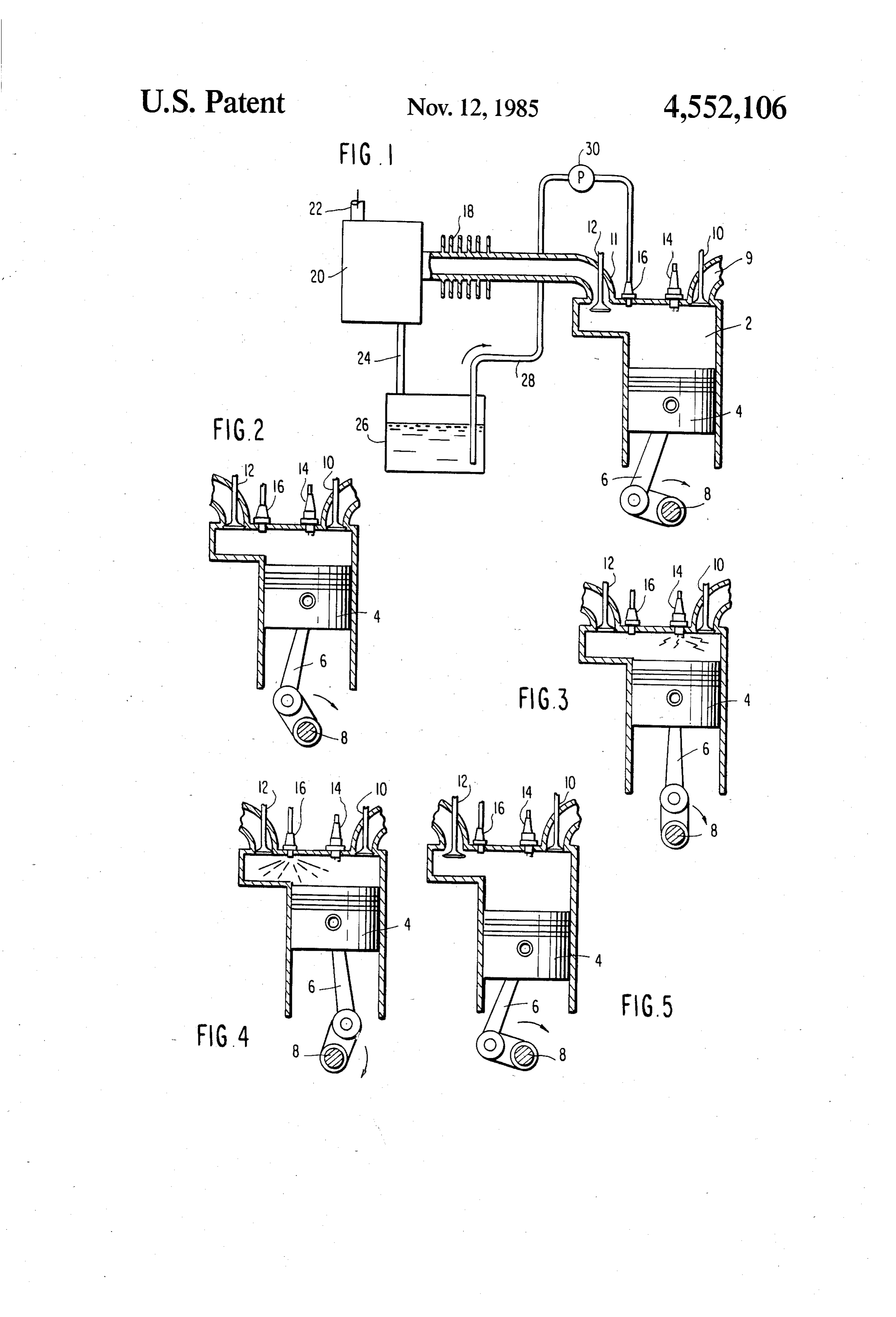
FIG. 2 illustrates the position of piston 4 as it is com
Page 2drawing sheetscan →
Page 3scan →
closed in this patent differs substantially from conven
INTERNAL COMBUSTON ENGINE tional internal combustion engines, functioning on a BACKGROUND OF THE INVENTION six-stroke cycle and having additional exhaust valves and exhaust gas chambers associated with each cylin 1. Field of the Invention der. U.S. Pat. No. 3,964,263 to Tibbs also discloses a The present invention relates to internal combustion six-stroke internal combustion engine wherein water is engines. Particularly, the present invention pertains to injected into the heated cylinder following the exhaust means and a method for increasing both the power and stroke. While the arrangement of Tibbs requires only a efficiency of conventional internal combustion engines. O single exhaust valve, it is still necessary that the timing 2. Description of the Related Art and operational sequence of a conventional engine be Internal combustion engines running on hydrocarbon altered so that it may function on a six-stroke cycle. fuel have long been used as a source of power. In recent U.S. Pat. No. 3,896,775 to Melby discloses a six-stroke years, however, the fuel inefficiency, noise, pollution, supercharged internal combustion engine wherein the and high cost of operation have become increasingly 15 exhaust from a first power stroke is returned to a cylin severe problems. der, along with new air, for a second power stroke. This Conventional internal combustion engines generally apparatus also requires substantial modification to operate on either a two-stroke or four-stroke cycle. A known engine designs so that it may operate on a six complete cycle in a four-cycle engine produces two stroke cycle. The complete revolutions of the crank shaft. Starting with all residual gases totechniques the employed to date exhaust atmosphere.
the piston at top dead center (TDC), as the piston 20 moves down, the intake valve opens, allowing the pis theIt problems is an object of the present invention to overcome associated with conventional internal ton displacement to create a vacuum, drawing a fuel-air combustion engines, mixture into the cylinder. The intake valve closes, and greater power outputand and to provide an engine having increased fuel efficiency.
the piston moves upwardly toward the cylinder head, compressing the fuel-air mixture in the cylinder. When 25 volumeIt is an object of the present invention to reduce the the piston reaches TDC (+/- a few degrees), an elec of exhaust emission from an internal combus trical spark ignites the compressed fuel-air mixture; the tion engine at any given power output. explosive expansion of the mixture drives the piston It is a further object of the invention to provide an downwardly in the power stroke. The exhaust valve internal combustion engine having cooler exhaust emis then opens, and an upward movement of the piston 30 sions, reduced emission noise, and emitting a lower expels the residual gases from the cylinder. level of contaminants to the atmosphere as compared to A two-stroke engine operates in much the same man prior art engines.
ner, combining the power, exhaust, intake and compres It is a further object of the present invention to pro sion strokes into a single revolution. vide both means and a method for converting waste The internal combustion process produces consider 35 heat produced by conventional engines into usable en able heat which is stored in the cylinder head, walls and ergy.
piston of the engine. This latent heat must be disposed It is a further object of this invention to provide both of before temperature levels become sufficiently high to means and a method for adapting presently available destroy the engine. In many conventional engines, the two-stroke and four-stroke engine designs to operate at preferred method for disposing of the heat is with a 40 substantially greater efficiency, thereby facilitating forced fan radiator and liquid coolant. manufacture of more highly efficient engines without Vast amounts of energy are wasted during operation extensive re-tooling costs.
of a conventional internal combustion engine. Thermal It is a further object of this invention to extend useful energy is wasted in the form of extremely hot gases engine life by reducing being exhausted to the atmosphere. Heat removed from 45 thereby placing less strainengine on operating temperature, the lubricants.
the engine parts by the coolant is also simply blown off into the atmosphere. Additionally, much of the energy SUMMARY OF THE INVENTION generated by the engine is consumed in driving the The present invention is directed to a two- or four pumps and fans of the cooling system. In short, only a small portion of the energy generated by the engine is 50 stroke internal combustion engine and to a related method of operation thereof. During engine operation, used to produce useful work.
Many devices and techniques have been developed in a non-combustible fluid is provided to the engine. Ther recent years for the purpose of increasing the power mal energy is transferred from the residual gases of output. and fuel efficiency of internal combustion en combustion to the non-combustible fluid, causing the gines. Most such devices have met with limited success; 55 fluid to expand as a gas. The energy of the expanding the nature of internal combustion engines, and the man gas is converted to mechanical power. The non-com ner in which they produce power, has changed little. bustible fluid may be provided to the cylinder(s) during Other techniques have been developed to provide the power stroke following ignition of the fuel, so that increased power output. One such technique includes the non-combustible fluid absorbs heat from the bur injecting a second combustible fluid into the engine 60 ning/burned fuel in the cylinder(s). The non-combusti cylinder, usually after primary ignition and combustion ble fluid comprises an element or compound exhibiting have occurred. Another technique is described, for high thermal expansion characteristics with noble char example, in U.S. Pat. No. 4,143,518 to Kellogg-Smith, acter over an extended temperature range. which discloses a six-stroke internal combustion engine. Provision is made for recovering the non-combustible Water is injected into the cylinders and is converted to 65 fluid, and for recycling it. The fluid may be recovered steam by the residual heat from the hydrocarbon igni after it is exhausted from the cylinder. This includes tion of the first power stroke, providing the motive means for separating the non-combustible gases from force for a second power stroke. The apparatus dis exhaust gases, for recondensing the non-combustible 4 gas to a fluid and for recycling the condensed fluid to be stroke. The non-combustible fluid, generally provided reinjected into the cylinder(s). in liquid form, vaporizes and expands within the cylin In a preferred embodiment, the non-combustible fluid der, increasing pressure during the power stroke and is provided to the cylinder(s) in liquid form. The liquid boosting power output. The present invention operates vaporizes and expands upon contacting the gases pro on a closed loop principle as will be discussed with duced by the burning of the ignited combustible fuel. reference to the drawings. The present invention in Following the power stroke, the contents of the cylin cludes means for recovering the non-combustible fluid der(s) are exhausted and cooled. The vaporized non from the cylinder, and returning the fluid to the cylin combustible fluid cools and condenses more rapidly der for repeated use.
than the gaseous products of combustion, thereby per 10 FIG. 1 illustrates the essential components of an en mitting recovery of the non-combustible fluid. The gine in accordance with a preferred embodiment of the recovered fluid is returned to the cylinder(s) during a present invention. The engine comprises at least one subsequent power stroke. conventional cylinder 2 having a piston 4 reciprocable The non-combustible fluid is provided to the cylin therein. The piston is connected to an arm 6 and a crank der(s) in a quantity sufficient to absorb a maximum 15 shaft 8 in the usual manner. An intake port 9 and a valve amount of heat in the ignited combustible fuel. The 10 provides a mixture of combustible fuel and air to the ignited fuel in the cylinder(s) is cooled by contact with cylinder, while an exhaust port 11 and a valve 12 per the non-combustible fluid, which absorbs heat there mits removal of spent fuel from the cylinder. An igni from. This inhibits heat buildup in the cylinder and tion means, such as a conventional spark plug 14, is permits the engine to run cooler. 20 provided for igniting the fuel.
Brief description of the drawings
An injector 16, which may be of conventional config uration, provides a non-combustible fluid to the cylin
FIG. 1 schematically illustrates the essential compo der. In a preferred embodiment, the fluid is provided to nents of an internal combustion engine in accordance the cylinder in the form of a liquid. with the present invention. 25 Exhaust from the cylinder, which will include spent FIG. 2 illustrates the apparatus of FIG. 1 in operation combustible fuels as well as the non-combustible gases, as it completes the compression stroke, with the piston passes through exhaust port 11 to a cooling means 18 approaching TDC. and a separator 20. The cooled non-combustible gas in FIG. 3 illustrates the apparatus of FIG. 1 upon igni the exhaustis separated from the spent combustible fuel. tion of combustible fuel therein, with the piston being 30 A characteristic of the non-combustible fluid is that it just past TDC. will condense much more quickly than the rest of the FIG. 4 illustrates the same apparatus in operation exhaust gases. Thus, the latter will exit through an ex upon injection of the non-combustible fluid during the haust 22, while the condensed fluid will pass through power stroke. conduit means 24 to a sump 26. A pump 30 draws the FIG. 5 illustrates the apparatus as it completes the 35 non-combustible fluid from the sump 26 through con exhaust stroke. duit means 28, and provides it again to injector 16. The
Detailed description of the
mode of operation of the apparatus of FIG. 1 will be
Invention
discussed with respect to FIGS. 2-5.
FIG. 2 illustrates the position of piston 4 as it is com
A conventional internal combustion engine generates 40 pleting the compression stroke, approaching TDC. mechanical power by igniting and expanding combusti Both ports 9 and 11 are closed at this point. As piston 4 ble fuel within a cylinder. The fuel is ignited when the reaches TDC (--/- a few degrees), spark plug 14 ig piston within the cylinder is at approximately TDC nites the combustible fuel in the cylinder. The ignited (+/- a few degrees). The expanding gases force the fuel expands, forcing piston 4 downward and turning piston downward, turning a crankshaft. However, once 45 crank shaft 8.
the ignited fuel has expanded fully, continued down During the power stroke, a non-combustible fluid is ward movement of the piston produces a vacuum injected into cylinder 2 by injector 16. This fluid within the cylinder. This must be overcome with inertia contacts the heated fuel in the cylinder, absorbs heat to make the engine continue to turn. A flywheel (not therefrom and becomes vaporized. The fluid expands shown) coupled with the crank shaft in a known man 50 rapidly upon vaporization, increasing the pressure ner, carries the piston through the remainder of the within the cylinder, preventing a vacuum from devel power stroke and through the exhaust stroke. The iner oping, and substantially increasing the power output of tia must be sufficient to continue to turn the engine the engine. Heat absorbed by the fluid reduces the tem through the intake and compression strokes as well. perature of gases within the cylinder, and reduces the The vacuum created during the latter portion of the 55 heating effect on engine parts.
power stroke impedes motion of the engine and seri The non-combustible fluid is preferably injected into ously reduces its power output. Evidence suggests that cylinder 2 in sufficient quantity to balance the heat the conventional engine runs in a vacuum during a produced by the burning fuel. The non-combustible portion of rotation of the crankshaft during the power fluid thus absorbs heat from the combustion gases be stroke (e.g., from approximately 45 degrees of rotation 60 fore latent heat can penetrate the cylinder parts and to about 180 degrees of rotation). The duration of the converts it to useful energy. The operating temperature vacuum portion of the power stroke could be reduced of the engine can be controlled in this manner. by providing additional combustible fuel to the cylin Following completion of the power stroke, exhaust der. This is the means used by conventional engines to port 11 is opened, as illustrated in FIG. 5, and the com increase power. 65 bined spent fuel and non-combustible fluid is exhausted The present invention overcomes this shortcoming of from cylinder 2.
the internal combustion engine by providing a non A great portion of the energy derived from the air combustible fluid to the cylinder during the power fuel mixture in internal combustion engines is wasted in 5 the form of heat. The present invention converts a large grees of the turn of the crank shaft. If this maximum portion of that heat, which is normally wasted, into pressure could be realized at approximately 90 degrees, usable mechanical power. the maximum transfer of energy would occur to the After being exhausted from cylinder 2 through ex crank shaft.
haust port 11, the residual mixture of vaporized non Present thinking with considerable evidence suggests combustible fluid and gases of combustion enters cool that the conventional engine runs in a vacuum from ing means 18. In cooling means 18, the exhaust mixture, somewhere around the 45 degree point to about 180 which is already at a relatively low temperature follow degrees on the power stroke. This situation changes and ing absorption of heat by the gas, is further cooled, the vacuum portion of the power stroke becomes less as facilitating condensation of the non-combustible fluid. 10 additional fuel/air mixture is added. As the vacuum The fluid will liquify when the temperature is reduced, portion of the stroke is reduced, engine energy produc and will separate in separating means 20 from the com tion increases.
bustion gases generated by the burned fuel. The remain ing gases are exhausted through exhaust means 22 in a in A primary feature of this invention is that an increase power can be derived from a non-combustible heavy conventional manner. 15 gas injected after flame-out, when the burning fuel has The condensed fluid passes through conduit means 24 reached its highest temperature. This corresponds with to sump 26, constituting a reservoir for the fluid. Pump about 20 degrees past TDC. At that point, the crank 30, or other suitable means, draws the fluid through shaft angle is in a more satisfactory position to convert conduit means 28 and returns it to injector 16 to be used expansion pressure of the non-combustible gas to me chanical energy. The quantity of non-combustible fluid
Fluids suitable for use in the present invention are non-combustible chemical elements or compounds hav injected can drive the piston to the 180 degree position, ing certain properties. They must be non-combustible, thereby substantially eliminating the partial vacuum of noble character, and exhibit good temperature expan that may exist in a conventional mode. sion characteristics. Examples of such fluids are the 25 forThe present invention provides means and a method increasing the power output of internal combustion halogens. The selection of a particular non-combustible engines fluid to be used may be made dependent on the environ any givenwithout increasing fuel consumption. Thus, at power level, fuel consumption can be greatly ment in which the engine will function.
Compared with a conventional engine, the present reduced as compared to conventional engines now in invention is thus capable of producing substantially 30 use. The volume of emissions from the engine is also increased power without substantially increasing fuel reduced due to the reduced fuel consumption. Addi consumption. tionally, since much of the thermal energy formerly In the case where the non-combustible fluid is in expelled into the atmosphere is converted into useful jected at or about the point of flame-out, after the burn power exhaust from the engine of the present invention ing fuels have reached their maximum temperature, the 35 is substantially cooler than that from conventional en residual heat in the gases has not penetrated the cylinder gines, thus reducing thermal pollution. walls, head, piston, etc., as time is required for latent The closed loop system of the present invention, heat to penetrate and build up on these parts. The non utilizing a non-combustible fluid and operating in con combustible fluid, injected as a liquid, will vaporize and junction with conventional fuel, effectively converts geometrically reduce the temperature of the burning or 40 waste heat into useful energy without requiring addi "burned gases of combustion while expanding to accom tional consumption of any fuel whatsoever. This effec modate this heat. The expanding non-combustible fluid tively reduces operating costs of the engine, and con (now in a gaseous state) will drive the piston down, serves hydrocarbon fuels which are becoming increas producing power to the bottom of the power stroke. ingly scarce and expensive. An engine in accordance The non-combustible fluid, being of noble character, 45 with the present invention will run more efficiently and will readily liquify when the temperature is reduced, more quietly than conventional engines, emitting sub allowing recovery. This results in a closed system oper stantially reduced pollutants into the atmosphere. As a ating in conjunction with an open system (comprising further advantage, engine life will be extended. the exhaust gas from combustion). The residue from the The invention is described here with respect to a burned air/fuel mixture remains a gas and can be ex 50 single cylinder of an engine operating on a four-stroke hausted to the atmosphere. The temperature and vol cycle. It is to be understood that the present invention is ume of the exhaust gas (from the burned air/fuel mix also applicable to engines having multiple cylinders as ture) is reduced to approach ambient before being ex well as to engines operating on a two-stroke cycle. hausted. This reduces the volume of exhaust as well as The invention may be embodied in other specific heat contamination of the environment. 55 forms without departing from the spirit or essential Since the conventional combustion engine is thought characteristics thereof. The present embodiments, to run in a vacuum for up to 50% of the power stroke, therefore, are to be considered in all respects as illustra this must be overcome with inertia to make the engine tive and not restrictive, of the scope of the invention continue to turn. The flywheel carries the piston being indicated by the appended claims rather than by through the exhaust stroke as well as through a partial the foregoing description, and all changes which come vacuum on the intake stroke. This inertia must continue within the meaning and range of equivalency of the to turn the engine and be of sufficient magnitude to claims are therefore intended to be embraced therein. complete the compression stroke. I claim as my invention: With the approach taken by the present invention, the 1. An internal combustion engine operating on a two air/fuel mixture ignites at about TDC (+/- a few 65 stroke cycle or a four-stroke cycly having a power degrees), as is done in a conventional engine. In one stroke, comprising:
embodiment, ignition occurs about 2 degrees past TDC. means for providing a combustible fuel to said engine Maximum pressure is experienced in the next few de at the start of the power stroke;
Page 6scan →
first means for igniting said fuel during the power means for converting expansion of said fluid to me stroke to produce mechanical power; chanical power during the power stroke, means for providing a non-combustible fluid to said wherein said non-combustible fluid comprises a fluid engine during the power stroke after said first having good temperature expansion characteristics means has ignited said fuel and after said ignited 5 and which condenses at a substantially faster rate fuel has substantially reached the point of flame-out than burned combustible fuel exhausted from the in order to transfer thermal energy from said ig engine, and nited fuel to said non-combustible fluid, thereby wherein said non-combustible liquid comprises a causing expansion of said fluid during the power halogen. k k k
Provenance
- Collection
- Patents citing this work
- Pages
- 6
- Method
- pdftotext (the PDF's own text layer) + pdftoppm 300dpi page scans
- Patent office record
- patents.google.com →
- Source
- Google Patents citing-documents table
- Assignee
- John P. Ohl
- Published
- 1985-11-12
- Transcribed from
- patentimages.storage.googleapis.com →