

patent · US4557226A
Device for returning the blow-by rate from the crankcase into the system of a supercharged internal combustion engine
10 December 1985
Text
Page 1bibliographic recordscan →
United States Patent (19)
Mayer et al.
54 DEVICE FOR RETURNING THE BLOW-BY
RATE FROM THE CRANKCASE INTO THE
SYSTEM OF A SUPERCHARGED INTERNAL
COMBUSTON ENGINE
75 Inventors: Andreas Mayer, Niederrohirdorf,
Switzerland; Rudolf Stissi, Los
Angeles, Calif.
Assignee: BBC Brown, Boveri & Company,
Limited, Baden, Switzerland
(51) Int. Cl." ............................................. F01M 13/00 (52) U.S. C. .................................. 123/41.86; 123/572 (58 Field of Search ..................... 123/41.86, 572-574,
3,246,639 4/1966 Oliner .................................. 123/572 3,456,759 7/1969 Henry-Biabaud ... 123/41.86 3,616,779 11/1971 Newkirk............... ... 123/4.86 3,754,538 8/1973 Ephraim, Jr. et al. 123/41.86 3,990,421 11/1976 Grainger. ... 123/572 4,488,532 12/1984 Mayer ................................. 123/559
Primary Examiner-William A. Cuchlinski, Jr.
Attorney, Agent, or Firm-Oblon, Fisher, Spivak,
McClelland & Maier
In internal combustion engines (1), the sealing of the combustion chamber by pistons and piston rings is not absolute. Throughout the working cycle, gases from the cylinder enter the crankcase (1a). These blow-by gases must be able to escape from the crankcase (1a). In a device for returning the blow-by gases into the system of an internal combustion engine (1) supercharged with a gas-dynamic pressure-wave supercharger (10), it is envisaged that a gas delivery unit designed as an ejector (20) generates a reduced pressure in the crankcase (1a). The ejector (20) is operated with a propellant gas from a line (16) which is taken from the supercharger airline (13), a control (8) placed in the propellant gas line (16) ensuring that the reduced pressure in the crankcase (1a) never exceeds a defined value. The blow-by gases in the line (2) flow through an oil separator (4) and, mixed with the propellant gas in the line (16), are then re turned into the exhaust line (15) of the engine system. 12 Claims, 5 Drawing Figures
Drawings
Page 2drawing sheetscan →
Page 3drawing sheetscan →
Page 4drawing sheetscan →
Page 5drawing sheetscan →
Page 6scan →
supercharging air. The BB gases to be extracted from
DEVICE FOR RETURNING THE BLOW-BY RATE the crankcase flow through a control device which is FROM THE CRANKCASE INTO THE SYSTEM OF placed in the extraction line and which controls the A SUPERCHARGED INTERNAL COMBUSTION reduced pressure desired in the crankcase. The ex ENGINE tracted BB gases are then returned into the system of FIELD OF THE INVENTION the internal combustion engine. Such a circuit has the aim of obtaining vigorous extraction by means closely
The present invention relates to a device for return connected with the engine.
ing the blow-by gases from the crankcase having a gas However, this presupposes that the propellants em delivery unit which is driven by a propellant and which, 10 ployed possess sufficient stored energy. Under full load, when a control device placed in the extraction line is this is generally the case, but it is not the case when the connected in, generates a reduced pressure in the crank engine runs under part load. In such cases, the super CaSC.
charging pressure can hardly maintain the extraction of
BACKGROUND OF THE INVENTION 15 the BB gases from the crankcase, even if the control In internal combustion engines, the sealing of the device is by-passed.
If, furthermore, an oil separator were to be provided combustion chamber by the pistons and piston rings is not absolute. Throughout the working cycle, gases pass downstream of a pump system, it would no longer be possible to establish the desired reduced pressure in the from the cylinder into the crankcase. These gases-be crankcase.
low called blow-by gases or BB gases for short-must 20 be able to escape from the crankcase. This is usually OBJECT OF THE INVENTION effected by providing an orifice on the valve cover or engine block. It is this point where the invention is to provide a Protection of the environment demands prevention remedy. The invention the object of generating a con of an escape of oil from the engine. In naturally aspi 25 trolled, limited reduced pressure in the crankcase rated engines, the oil mist blown out of the crankcase throughout the operation range in such a way that the (BB gases) is passed back into the induction side of the BB gases can be sufficiently cleaned in an appropriately engine, so that external oil contamination is avoided. In designed oil separator placed upstream of the gas deliv fact, this measure has become a statutory regulation for ery unit, before the BB gases are returned into the sys gasoline engines in many countries. Corresponding pro 30 tem of the internal combustion engine. posals have the aim of introducing this technique also in SUMMARY OF THE INVENTION the diesel engine.
In some countries, regulations provide that, in spark In the internal combustion engine supercharged with ignition engines, a reduced pressure must prevail in the a gas-dynamic pressure-wave supercharger, the forego crankcase throughout the load and speed range, in 35 ing object is achieved by running the gas delivery unit order to avoid an escape of oil through the seals of the with a propellant gas which is branched off on the air crankcase. In principle, only a slightly reduced pressure side upstream of the starter valve flap placed down should prevail in the crankcase throughout the operat stream of the gas-dynamic pressure-wave supercharger. ing range, since, the greater the reduced pressure, the more oil is disadvantageously extracted together with ADVANTAGES OF THE INVENTION the BB gas. It is to be regarded as the essential advantage of the It is then customary to return the BB gases into the invention induction line of the internal combustion engine up combustionthat, at low-pressure states in the internal engine, the starter valve flap is closed, so stream of the air filter or to pass them into the open through an oil separator. In the case of a return of the 45 that the propellant gas, branched off on the air side upstream thereof, contains sufficient energy from the
BB gases into the induction line, some motor manufac compression by the gas-dynamic pressure-wave super turers see an advantage in valve lubrication, but others charger. It is thus ensured that the gas delivery unit, do not utilise the BB return for this purpose.
The oil separator can be integrated in the valve cover which preferably is an ejector, is operated throughout the operating range with a sufficiently large propellant or it can be inserted as an individual component. It 50 gas energy for fulfilling its intended task-namely, to filters out a large proportion of the oil contained in the
BB gas before the BB gas passes into the open or is generate, via the oil separator, a reduced pressure in the returned into the engine-that is to say, fed to combus crankcase. A control which is placed in the propellant tion. gas line and through which a clean medium always When the oil separators nowadays available on the 55 flows, fulfils the task, generally and in particular under market are used, however, a considerable quantity of oil full load, of maintaining the reduced pressure in the still breaks through. The requirement of establishing a crankcase at a predetermined value, so that losses with reduced pressure in the crankcase hitherto did not per respect to the supercharging pressure and the tempera mit the use of oil separators having a higher degree of ture of the supercharging air can be minimised. purification of the BB gas. In fact, higher oil separation 60 GENERAL DISCUSSION OF THE INVENTION causes a greater pressure drop in the filter, so that the desired reduced pressure in the crankcase is no longer Propellant gas rate control and pressure-modulation ensured. control are preferred embodiments of the invention For an internal combustion engine supercharged by a with respect to the type of control.
turbo-charger, printed publication GB-A 2006 329 has 65 In a further preferred embodiment of the invention, disclosed the extraction of the BB gases from the crank the gas delivery unit is a venturi diffusor which is case with the aid of a pump system designed as an ejec placed in the exhaust line. The venturi nozzle can then tor orjet pump. The propellant used here is preferably be supplemented by an ejector partly fed by the slip 7 stream, so that the suction effect of the venturi diffusor nal combustion engine 1 or the crankcase 1a cannot is reinforced during motion. flow back into the oil separator 4. In low-pressure In a further preferred embodiment of the invention, states, in particular under part load in the internal com the cleaned BB gases from the crankcase are returned bustion engine 1, the starter valve flap 19 is closed, so into the low-pressure exhaust line of the system of the that, in the supercharging airline 13 upstream of the internal combustion engine. The advantage is that the latter, the pressure level can rapidly build up by means temperatures at this point are so low that cracking pro of the working pressure-wave supercharger 10. The cesses can hardly take place there. Due to the presence propellant gas in the propellant gas line 16 tapped off of an oil separator with a very high separation effi the supercharging air line 13 has sufficient energy for ciency, it can be assumed that virtually oil-free waste 10 ensuring the necessary suction effect in the ejector 20, gases leave the exhaust system. even during part load phases of the internal combustion Moreover, the BB gases from the crankcase-in a engine 1. During these phases, the fresh air supply for further preferred embodiment-are utilised for valve the internal combustion engine 1 is maintained through lubrication when the internal combustion engine is the starter valve by-pass 19a, idling. A non-return valve provided here prevents a 15 The controller 8 in the propellant gas line 16 has the flow of supercharging air into the line of the BB gases task, by means of the controller signal 9, of preventing when the internal combustion engine picks up load. the magnitude of the reduced pressure in the crankcase
Brief description of the drawings
1a from rising above a defined value, since a great risk in this arrangement is precisely that-in particular
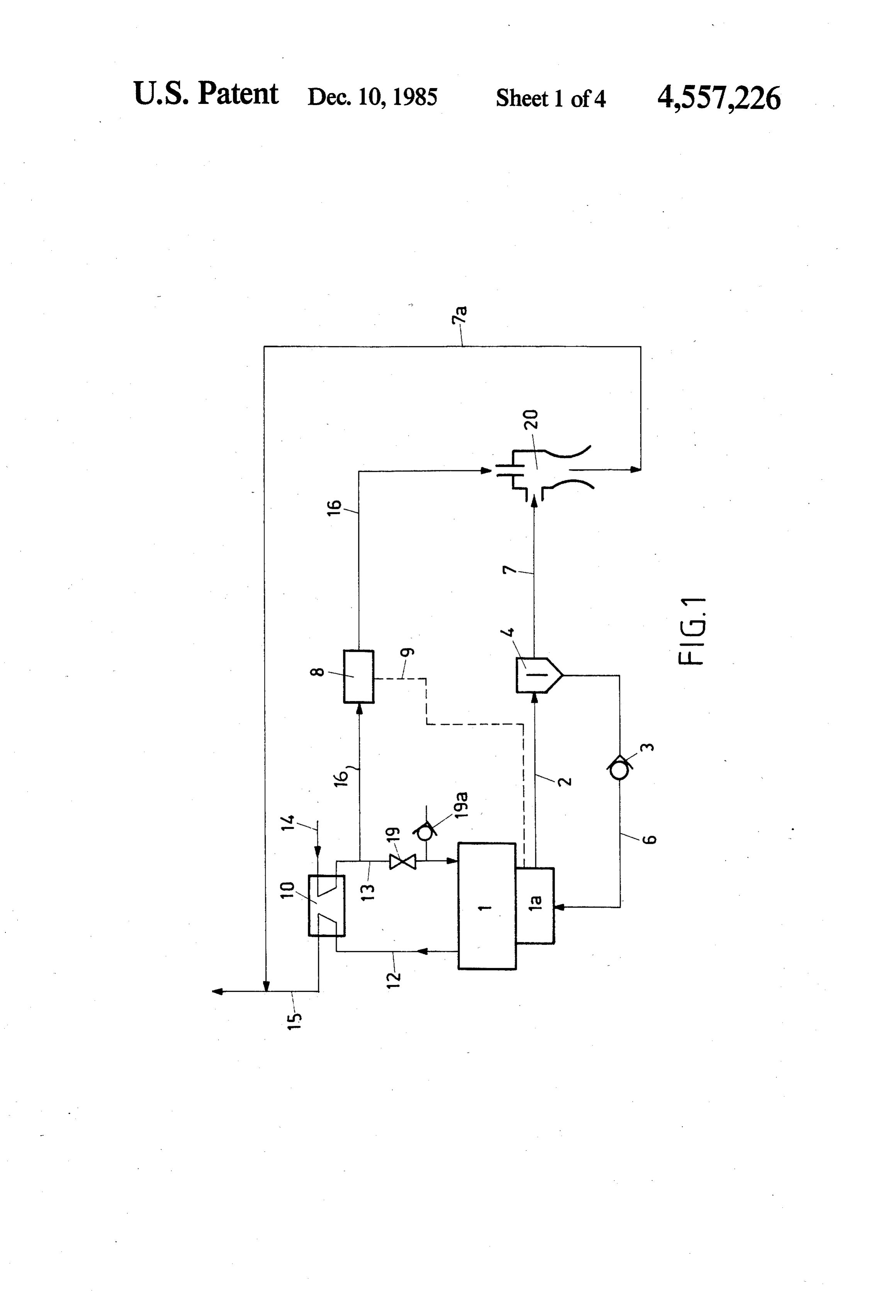
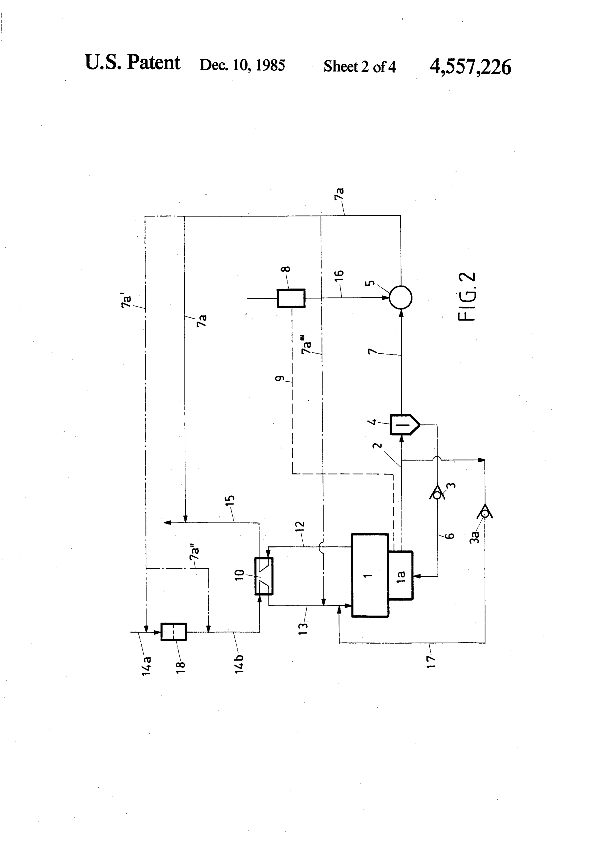
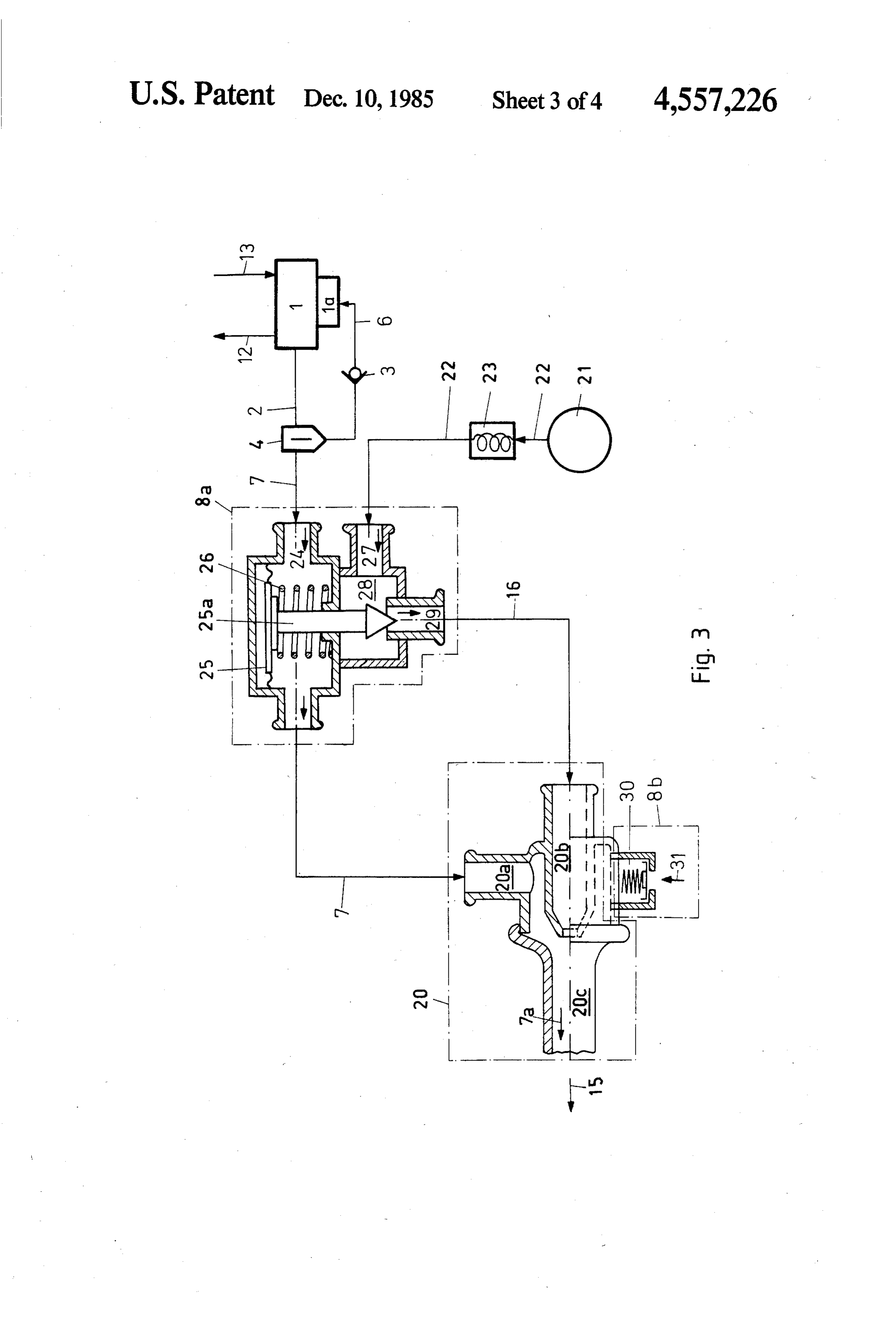
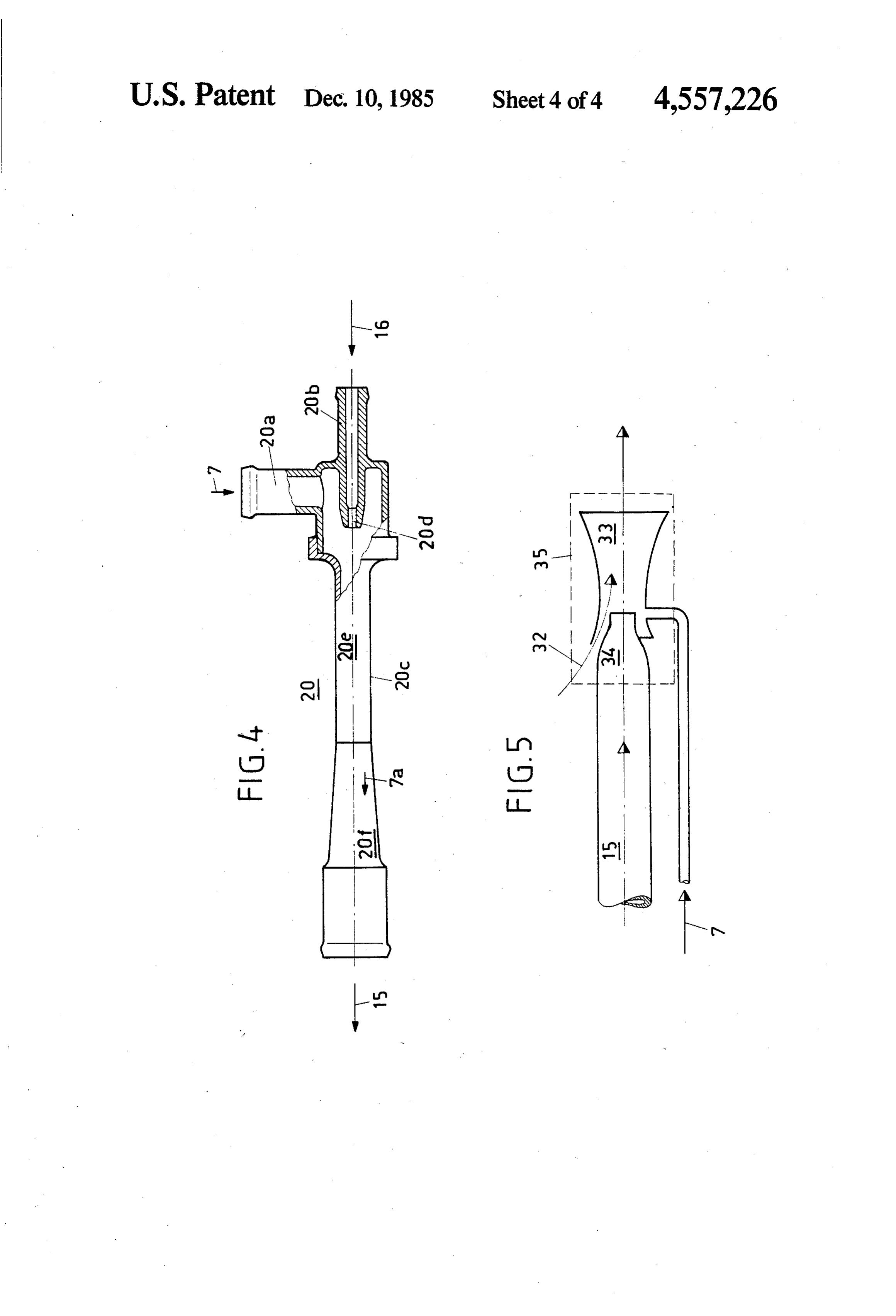
Illustrative embodiments of the invention are dia 20 under full load-excessive quantities of oil are removed grammatically shown in the drawing in which: from the internal combustion engine 1. FIG. 1 shows a diagram of a device for cleaning and FIG. 2 is a further embodiment of the arrangement returning the BB gases into the system of an internal described with reference to FIG. 1. Here, in FIG. 2, the combustion engine supercharged with a gas-dynamic point is only to indicate the possible arrangements for pressure-wave supercharger. 25 the induction of fresh air and for the return of the FIG. 2 shows a further diagram with various points cleaned BB gases in the line 7 into the system of the to which the BB gases are returned. internal combustion engine 1. Moreover, the ejector 20 FIG. 3 shows a possible way of delivering the BB in the FIG. 1 embodiment has been replaced by a pump gases, with propellant gas rate control, pressure-modu 5, which also serves as a gas delivery unit. An induction lation control and ejector. 30 air line 14a, 14b introduced air through an air filter 18, FIG. 4 shows an ejector as the gas delivery unit. before the air is compressed by the engine exhaust gases FIG. 5 shows a venturi nozzle as the gas delivery introduced into the pressure-wave supercharger 10 via unit. the line 12 to provide supercharging air in the line 13 for All the elements not necessary for direct understand the internal combustion engine 1. The cleaned BB gases ing of the invention have been omitted. The direction of 35 in line 7 and the propellant gas in the line 16 are-as flow of the working media is marked with arrows. In already shown by FIG. 1-returned as a gas mixture in the various figures, identical elements are provided with the line 7a into the exhaust line 15. Depending on the identical reference numerals. layout of the arrangement, the gas mixture in the line 7a DETALED DESCRIPTION OF THE can also be returned into the induction airline 14a up 40 stream of the filter 18 by means of the line 7a', or into
PRESENTLY PREFERRED EMBODIMENTS the induction airline 14b downstream of the filter 18 by According to FIG. 1, the internal combustion engine means of the line 7a', or into the supercharging airline 1 is connected on the air side via a supercharging airline 13 by means of the line 7a'.
13 to a gas-dynamic pressure-wave supercharger 10. When the internal combustion engine 1 is idling, the The latter is provided on the low-pressure side with an 45 BB gases in the line 2 can be used for valve lubrication induction line 14 for fresh air. The mode of operation of in the line 17. A non-return valve 3a prevents a flow of the gas-dynamic pressure-wave supercharger 10 is ex supercharging air from the line 13 into the BB gas line plained in Swiss Patent Specification No. 418 730. The 2 when the internal combustion engine picks up load. engine exhaust gases pass into the pressure-wave super FIG. 3 shows the use of the ejector 20, with the asso charger 10, via a line 12. From the pressure-wave super 50 ciated control. It is to be noted here that the propellant charger 10, the engine exhaust gases are expelled, after gas rate control 8a described here is not restricted to a they have given up their energy, via an exhaust line 15 supply of propellant gas from the supercharging airline into the atmosphere. A starter valve flap 19 is placed in 13 of the gas-dynamic pressure-wave supercharger 10 the supercharging airline 13. A propellant gas line 16 (see FIG. 1). According to FIG. 3, the working gas in branches off between the pressure-wave supercharger 55 the line 22 used as the propellant gas is taken from a 10 and the starter valve flap 19. The propellant gas pressure accumulator 21. Engine exhaust gas as the taken in this line from the supercharging airline 13 is working gas in the line 22 can be cooled and cleaned in passed to a gas delivery unit, which is an ejector 20 in an assembly 23, in order to prevent fouling and coking the present example. The ejector 20 ensures that a re of the BB oil. Of course, the propellant gas can also be duced pressure is generated in the crankcase 1a. The BB 60 taken from the pockets of a gas-dynamic pressure-wave gases flowing out of the crankcase 1a via a line 2 pass supercharger. As already stated above, the propellant through an oil separator 4 and then, as cleaned BB gas rate control 8a has the task of restricting the work gases, reach the exhaust line 15 via the line 7, the ejector ing gas in the line 22 or the propellant gas rate to the 20, and a BB gas/propellant gas mixture line 7a. The oil required minimum.
separated out in the oil separator 4 is returned into the 65 The cleaned BB gases in the line 7 flow through the engine system 1, 1a via the oil return 6, whereby the oil diaphragm chamber 24 and then enter the suction loss can be substantially reduced. The safety valve 3 branch 20a of the ejector 20. The crankcase pressure placed in the oil return 6 ensures that oil from the inter thus prevails in the diaphragm chamber 24. The position 8 of the diaphragm 25 sets itself via the pressure differ high separation efficiency, must also be added to this. ence between the two sides of the diaphragm, the spring The venturi nozzle 34 is therefore advantageously in 26 automatically controlling the degree of throttling stalled immediately upstream of the end of the exhaust which the working gas in the line 22 undergoes in the pipe, that is to say where the exhaust back-pressure is propellant gas rate control 8a. The working gas in the virtually equal to atmospheric pressure. In an adjoining line 22 enters the propellant gas rate control 8a through diffusor 33, the exit velocity is reduced or pressure is the inflow orifice 27, completely fills the expansion recovered.
chamber 28 and then flows out again as the propellant The venturi diffusor 35 can be structurally designed gas in the line 16 from the controlled exit orifice 29. The in such a way that, at high vehicle speeds, the slipstream less the working gas in the line 22 is throttled, the higher 10 32 is also utilised for generating a reduced pressure in the pressure of the modified working gas-now called propellant gas in conformity with the preceding de the venturi nozzle 34. Accordingly, an additional ejec scription-and the greater the propellant gas rate flow pellant gas.is As tor effect obtained with the slipstream 32 as the pro a result, the low-pressure flushing of the ing through the propellant branch 20b. This in turn has the effect of increasing the suction effect of the ejector gas-dynamic pressure-wave supercharger (FIG. 1, item 20. When the suction effect of the ejector 20 is in 15 10)Inisaddition, additionally improved. the diffusor 33 can be fitted with a baffle creased, the reduced pressure in the crankcase 1a is intensified, and it is held at a predetermined value by the (not shown) for pressure recovery. We claim:
propellant gas rate control 8a. The gas mixture 7a flows 1. Device for returning the blow-by gases from the through the pressure branch 20c of the ejector 20 and is crankcase into the system of a supercharged internal then returned into the exhaust line 15. 20
The needle 25a actuated by the diaphragm 25 can also driven by a engine, combustion having a gas delivery unit which is propellant and which, when a control de dip directly into the propellant branch 20b and, by its vice position, vary the inlet area of the propellant branch or ates aplaced in the extraction line is connected in, gener the outlet area of the propellant nozzle, these areas internalreduced pressure in the crankcase, wherein the determining the throughput of propellant gas. The re 25 dynamic combustion pressure-wave engine is supercharged by a gas supercharger and the propel duced pressure in the crankcase 1a can also be limited by a pressure-modulation control 8b. When the reduced lant for the gas delivery unit is gas which is taken from pressure predefined in the propellant branch 20b be the output of the gas-dynamic pressure-wave super comes excessive, the snifter valve 30 opens and air 31 charger in a propellant line and which is controllable by means of a controller placed in the propellant line in flows in, thus establishing equilibrium.
The ejector 20 shown in FIG. 4 may be made of 30 such a way that, throughout the operating range, a plastic. It essentially consists of a suction branch 20a, inreduced pressure of not greater than - 50 mbar prevails the crankcase.
propellant branch 20b, pressure branch 20c, propellant nozzle 20d, mixing tube 20e and diffusor 20f. The pro lant2. line Device according to claim 1 wherein the propel branches off on the air side downstream of the pellant gas 16 passes via the propellant branch 20b into 35 gas-dynamic pressure-wave supercharger and upstream the ejector 20 and is accelerated in the propellant nozzle of a starter valve flap. 20d. The cleaned BB gases in the line 7 flow into the 3. Device according to claim 1 wherein the propel suction branch 20a. In the mixing tube 20e, the propel lant gases from the line 16 and BB gases from the line 7 dynamic lant line is connected to one of the pockets of the gas come into mutual contact, the BB gases 7 from the line pressure-wave supercharger. being accelerated by an exchange of momentum. The ery4.unit Device according to claim 1 wherein the gas deliv is an ejector.
diffusor 20f has the task of converting the velocity en ergy of the gas mixture 7a into pressure energy. 5. Device according to claim 4 wherein the ejector is The ejector 20, the dimensions of which, at a total made of plastic.
length of about 200 mm and an overall height of about 6. Device according to claim 4 wherein the ejector is 50 mm, make installation very easy, can be mounted at 45 connected to the internal combustion engine system by any desired point. It can be freely suspended in hoses, or hoses.
it can be fixed by means of clamps or clips to the engine. 7. Device according to claim 1 wherein the oil sepa The position can thus be determined under the aspects rator is provided upstream of the gas delivery unit. of short lines, in order to reduce the costs and pressure 8. Device according to claim 1 wherein the degree of drops, and good accessibility. The line carrying the 50 reduced pressure in the crankcase is controlled by propellant gas should have an internal diameter which means of a propellant gas rate control.
is nowhere less than the minimum of 7 mm, and should 9. Device according to claim 1 wherein the degree of withstand a supercharging pressure of 2 bar and a pro reduced pressure in the crankcase is controlled by pellant gas temperature of 160° C. maximum. The re means of a pressure-modulation control.
maining connections of the ejector 20 do not have to 10. Device according to claim 1 wherein an exhaust meet any demands going beyond the usual motor vehi 55 line is operatively connected to the engine and the gas cle standard. delivery unit is a venturi nozzle placed in the exhaust As the pump, FIG. 5 shows a venturi nozzle 34 with line.
a diffusor 33, which are placed in the exhaust line 15. 11. Device according to claim 1 wherein the cleaned The energy of the low-pressure gas is used for generat 60 gases from the crankcase are returnable to a point in the ing a reduced pressure in the exhaust line 15 and for gas-dynamic pressure-wave supercharger where a re venting the cleaned BB gases in the line 7 into the latter. duced pressure prevails.
The criterion for the use of such devices is the exhaust 12. Device according to claim 1 wherein, when the gas back-pressure which must be overcome. Immedi internal combustion engine is idling, valve lubrication is ately downstream of the gas-dynamic pressure-wave effected by the blow-by gases from the crankcase, a supercharger (FIG. 1, item 10) this back pressure is 65 non-return valve preventing a flow of supercharging air about 600-800 mm water gauge, depending on the flow into the line of the blow-by gases when the internal velocity. The pressure drop in the oil separator (FIG. 1, combustion engine picks up load.
item 4), which in this case should have a particularly 2k t s xt t
Page 9scan →
United states patent and trademark office
Certificate of correction
INVENTOR(S) : Andreas Mayer, et all
It is certified that error appears in the above-identified patent and that said Letters Patent is hereby corrected as shown below:
-- The priority information on this Letters Patent has been omitted. Please add the following priority number:
6106/83-6 Switzerland l4.ll. 83-eigned and Sealed this
Eighteenth D 2 y of February 1986
Seal)
Attest:
Donaldj. quigg
Attesting Officer Commissioner of Patents and Trademarks
Provenance
- Collection
- Patents citing this work
- Pages
- 9
- Method
- pdftotext (the PDF's own text layer) + pdftoppm 300dpi page scans
- Patent office record
- patents.google.com →
- Source
- Google Patents citing-documents table
- Assignee
- Bbc Brown, Boveri & Company, Limited
- Published
- 1985-12-10
- Transcribed from
- patentimages.storage.googleapis.com →