

patent · US4567879A
Prismatic solar beam concentrator
4 February 1986
Text
Page 1bibliographic recordscan →
United States Patent (19)
Clegg
(54) CONCENTRATOR
PRISMATIC SOLAR BEAM
76 Inventor: John E. Clegg, 2320 Keystone Dr., Orlando, Fla. 32806
Int. Cl." ................................................. F24J 2/ 52 U.S. Cl. .................................... 126/440; 126/417;
4,267,826 5/1981 Hitt, Jr. ............................... 27, 4,337,759 7/1982 Popovich et al. 126/440 x 4,492,439 1/1985 Clegg ........................... ... i26/446X
FOREIGN PATENT DOCUMENTS
SeS
Primary Examiner-Larry Jones
A prismatic beam concentrator comprising two equilat eral double prisms No. 1 and three equilateral double prisms No. 2 mounted above an expansion flow tube. The prisms receive two convergent incipient beams of diffused sunlight and emit a concentrated sheet beam onto the exterior wall of the expansion flow tube. An expansion flow tube is a straight elongate conical tube with an inlet orifice of minimum diameter (5 mm) and an outlet orifice of maximum diameter (25 mm). Water circulating through the tube is heated by the concen trated sheet beam. The warm water expands outward against the interior wall of the tube and deflects toward the outlet orifice, which is the direction of flow. The deflection of water in the direction of flow increases the rate of flow and decreases the pressure that need be applied by the pump.
1 Claim, 3 Drawing Figures
Drawings
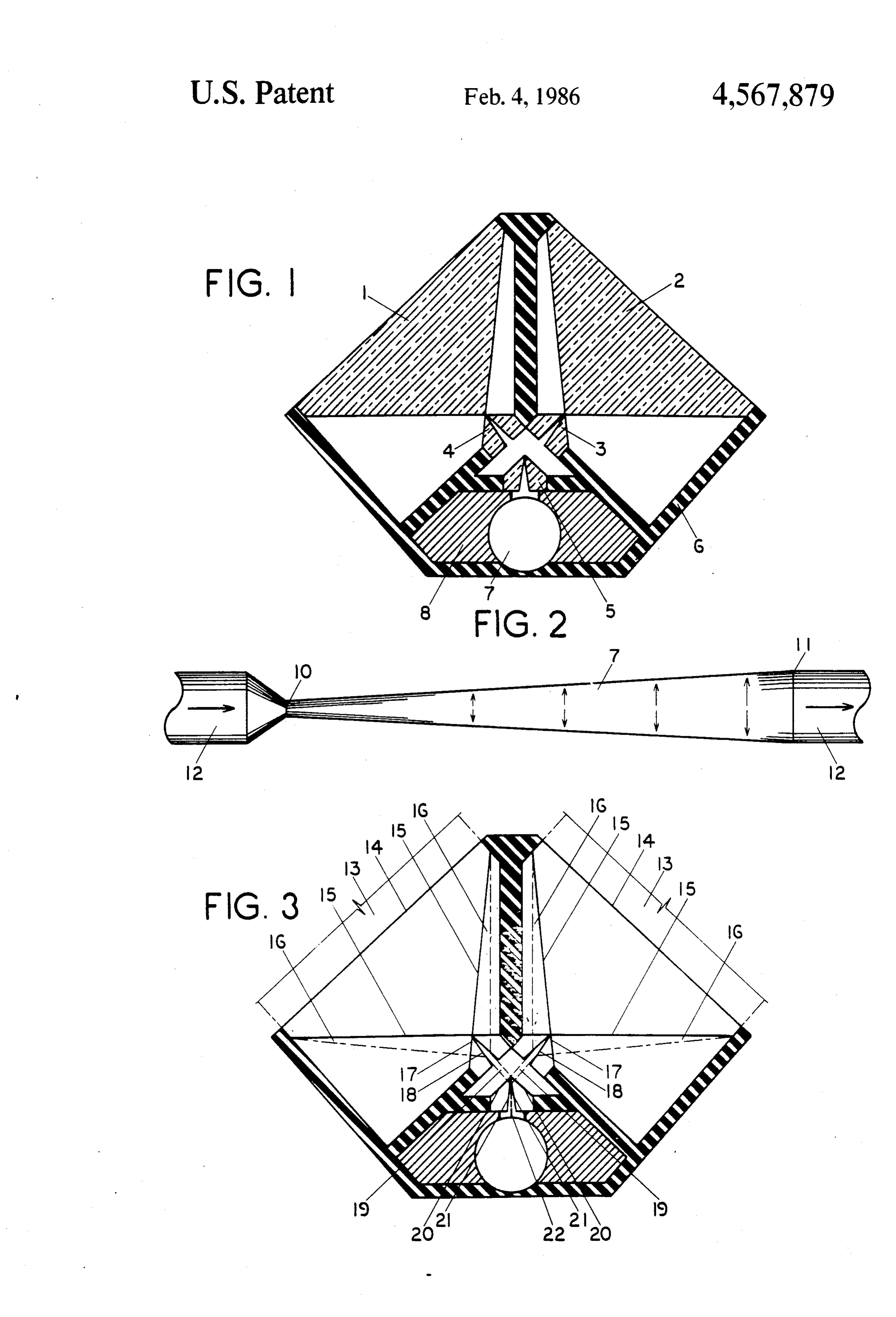
FIG. 1 is an elevation of the prismatic solar beam I claim;
Page 2drawing sheetscan →
Page 3scan →
by angular wedge faces 15 of prisms 1 and 2, forming
PRISMATIC SOLAR BEAM CONCENTRATOR two concentrated convergent rectangular beams 16. Beams 16 are transmitted by angular wedge faces 17
BACKGROUND and refracted by angular V-groove faces 18 of prisms 3 Prior art includes the Prismatic Wall Heater, U.S. Pat. 5 and 4, forming two concentrated convergent sheet No. 4,527,546 dated 7/9/85 by this inventor. This heater beams 19.
has an equilateral double prism No. 1 and equilateral The prismatic planes of prisms 1, 2, 3 and 4 are in double prism No. 2 mounted on a roof and projecting a clined 42.5' from the vertical plane. concentrated sheet beam through a cavity in a wall to a 10 Beams 19 are transmitted by angular wedge faces 20 metal baseboard plate at the bottom of the wall. and refracted by angular V-groove faces 21 of prism 5, Concurrent art includes the Prismatic Beam Concen forming concentrated sheet beam 22 which is emitted in trator, Ser. No. 661,988 dated 10/18/84 by this inventor. the vertical prismatic plane onto the exterior wall of This concentrator is identical to the concentrator dis expansion tube 7.
closed in this application. 5 Each refraction reduces the beam width by a factor Concurrent art also includes the Expansion Flow of 0.1414. There are three refractions, so the factor of Tube, Ser. No. 730,919 filed 5/6/85 by this inventor. total reduction of width of incipient beams 13 is 0.0028, This tube is much shorter than the tube which will be as follows;
used in practice.
DRAWINGS 20 Incipient beam width x0.0028 = concentrated beam
FIG. 1 is an elevation of the prismatic solar beam I claim;
concentrator with the prisms shown in section. 1. A prismatic solar beam concentrator comprising; FIG. 2 is a longitudinal section of the expansion flow a. two equilateral double prisms (1,2), each having a tube. planar face (14) and two angular wedge faces (15), FIG. 3 is an elevation of the prismatic solar beam 25 with the prismatic plane bisecting the planar face concentrator with a ray diagram. (14) and the edge formed by the junction of the two DESCRIPTION angular wedge faces (15) being inclined 42.5 from the vertical plane,
FIG. 1 is an elevation of the prismatic solar beam b. two equilateral double prisms (3,4) mounted below concentrator showing equilateral double prisms No. 30 prisms (1,2), each having two angular wedge faces One 1 and 2 mounted above equilateral double prisms (17) and two angular V-groove faces (18), with the No. Two 3, 4 and 5 inside housing 6, with the expansion prismatic plane bisecting the edges formed by the flow tube 7 mounted below prism 5 and packed in insu junction of the two angular wedge faces (17) and lation 8, the junction of the two angular V-groove faces (18) FIG. 2 is a longitudinal section of the expansion flow 35 being inclined 42.5 from the vertical plane, tube comprising a straight elongate conical tube 7 with c. an equilateral double prism (5) mounted below inlet orifice 10 of minimum diameter (5 mm), outlet prisms (3,4) and having two angular wedge faces orifice 11 of maximum diameter (25 mm) and copper (20) and two angular V-groove faces (21), with the tubing 12. A short tube with an exaggerated angle of prismatic plane bisecting the edges formed by the deflection off the interior wall is shown in order to better illustrate the mechanics of flow (horizontal ar junction of the two angular wedge faces (20) and rows), expansion (vertical arrows) and deflection in the the junction of the two angular V-groove faces (21) direction of flow. In practice the beam concentrator occupying the vertical plane, and and flow tube will be 6 meters (20 feet) or more in 45 d. an expansion flow tube mounted below the equilat length. eral double prism (5) and comprising a straight FIG. 3 is an elevation of the prismatic solar beam elongate conical tube (7) with an inlet orifice (10) concentrator with a ray diagram. Two convergent rect of minimum diameter and an outlet orifice (11) of angular incipient beams 13 of diffused sunlight are re maximum diameter.
ceived and transmitted by planar faces 14 and refracted 50
Provenance
- Collection
- Patents citing this work
- Pages
- 3
- Method
- pdftotext (the PDF's own text layer) + pdftoppm 300dpi page scans
- Patent office record
- patents.google.com →
- Source
- Google Patents citing-documents table
- Assignee
- Clegg John E
- Published
- 1986-02-04
- Transcribed from
- patentimages.storage.googleapis.com →