

patent · US4580530A
Method in the operation of a firing plant, and a firing plant for performing the method
8 April 1986
Text
Page 1bibliographic recordscan →
United States Patent (19)
Olrik
(54) METHOD IN THE OPERATION OF A
FIRING PLANT, AND A FIRING PLANT FOR
PERFORMING THE METHOD
76 Inventor: Henrik G. Olrik, Bakkegaardsvej 413, DK-3050 Humleback, Denmark
(30) Foreign Application Priority Data
Apr. 11, 1983 (DK) Denmark ............................. 1581/83 (51) Int. Cl......... - - - - - - - - - - - - F22B33/00 52 U.S. Cl. .................................... 122/1 A; 110/302;
4,173,450 1 1/1979 Schrank .............................. 431/4 X
FOREIGN PATENT DOCUMENTS
Primary Examiner-Edward G. Favors
Attorney, Agent, or Firm-Henry Sternberg; Bert J. Lewen
In a method in the operation of a firing plant of the type comprising a combustion furnace and heat exchanger means to transfer thermal energy from the flue gas of the furnace to its combustion air, wherein a vaporizable liquid, such as water, is added to the combustion air of the furnace, the combustion air pressure is reduced in the portion of the heat exchanger means where the said liquid is caused to evaporate, the necessary evaporation heat being taken from the flue gas of the furnace before the flue gas is discharged to the atmosphere. A plant for performing the method is characterized by containing a pump (11) which has a relatively small inlet opening (10) so that the pump (11) creates a negative pressure in the portion (12) of the heat exchanger (9) where the liquid, fed by means of a nozzle (13), evaporates. This allows large amounts of water to evaporate, and flue gas, which flows through the heat exchanger portion (14), is cooled to a low temperature. The flue gas will then condense, and this procedure is accelerated by the constriction (at of the flue (15) so that there is a positive pressure in the heat exchanger portion (14). According to the heat pump principle, the advantages are an unprecented low temperature level and humidity content of the discharged flue gas and a correspond ingly high efficiency of the firing plant.
15 Claims, 4 Drawing Figures
Drawings
Page 2drawing sheetscan →
Page 3drawing sheetscan →
Page 4drawing sheetscan →
Page 5drawing sheetscan →
Page 6scan →
pressure, which involves effective condensation of the
METHOD IN THE OPERATION OF A FIRING coolant, can in principle be compared to the pressure PLANT, AND A FIRING PLANT FOR conditions in the condenser of the heat pump systems. PERFORMING THE METHOD The pressure conditions can be established in several 5 ways, but require at least the presence of a pump and a
The invention concerns a method in the operation of predetermined dimensioning of the resistance to air a firing plant of the type comprising a combustion fur flow through the plant. The use of several pumps gives nace and heat exchanger means for the transfer of ther more freedom in the determination of the pressure con mal energy from the flue gas of the furnace to its com ditions in the plant, and it is therefore possible to pre bustion air. Such an art was described as early as in the 10 determine the pressure, e.g. in the furnace, as stated in U.S. Pat. No. 1,741,567. claim 4. This may be of importance as it is an advantage Later on it has repeatedly been attempted to make the that a plant for performing the method can be installed method more efficient by cooling the flue gas so much on an existing furnace, where the boiler is intended to be that a great portion of the water vapour as well as gase operated at atmospheric pressure, but there may con ous combustion products condense and give off conden 15 ceivably be cases where an absolute negative pressure is sation heat to a heat exchanger. The process of conden desired in the furnace to ensure that no gases will leak sation provides several advantages, such as the possibil out, and it may even be preferred in special cases to ity of firing moist, solid fuel, and firing with a large have a positive pressure in the furnace. The combustion excess of air without any increase in chimney losses, and air to the furnace will thus contain large amounts of that uninsulated flues, etc. can be used. These advan 20 vapour, mainly water vapour, and to avoid uninten tages get more pronounced with increased cooling of tional condensation of this water vapour the method is the flue gas, and in the vast majority of known plants preferably carried out as stated in claim 5, the super the lowest flue gas temperature is slightly greater than heating energy being taken from the firing plant, which the return water temperature of the firing plant. does not affect the net firing economy. The flue gas is The French Patent Applin. 7900 901 teaches the 25 preferably compressed by a liquid ring pump, which addition of water to the intake air to the furnace, which may be fitted in various ways after the furnace, and causes a drop in temperature because of the evaporation which involves the quite special advantage that the flue of the water, and it is possible additionally to cool the gas may be allowed to condense in this pump, this to flue gas somewhat over the above-mentioned prior art tally obviating problems of hammering. by bringing the flue gas into heat exchanging relation 30 The invention also concerns a firing plant for use in ship with the evaporation zone. the method, said firing plant being characterized by The object of the invention is to provide a method in pressure reducing means provided between the first the operation of a firing plant of the last-mentioned portion of the heat exchanger and the discharge open type, which provides an additional improvement in the ing to reduce the combustion air pressure in the first firing economy and an additional reduction in the air 35 portion of the heat exchanger in which said liquid evap pollution caused by the firing plant. orates. The pressure reducing means are so dimensioned The object is achieved by reducing the combustion with respect to the first portion of the heat exchanger as air pressure in the first portion of the heat exchanger so to provide a predetermined reduction in pressure for that the first portion of the heat exchanger serves as a accelerated evaporation of the liquid, which is prefera low pressure evaporator for the said liquid, since a con 40 bly water. The water is preferably added by the means siderable reduction in the pressure in the first portion of stated in claim 8, which are very simple and reliably the heat exchanger, where the added liquid evaporates, utilize the negative pressure in the first portion of the results in accelerated evaporation of the liquid, causing heat exchanger. In order that the method may be car the flue gases in the second portion of the heat ex ried out as stated in claim 3, the pressure reducing changer to be cooled to a particularly low temperature 45 means may be designed as stated in claim 9, or the com so that the condensation heat can be utilized to a greater pression means of claim 10 may be used, which are degree than before. When a large amount of water dimensioned in dependence upon the pressure drop condenses from the flue gas, a greater proportion of through the second portion of the heat exchanger and soot particles will be bound to the water. Moreover, less the flue to provide a predetermined positive pressure in water will be discharged through the flue so that also 50 the second portion of the heat exchanger. The conden smells and other sources of pollution associated with the sation will thus be accelerated, partly because of the water drops in the flue gas are reduced. The effective positive pressure and partly because the accelerated evaporation of the liquid provides a large variation evaporation of liquid in the combustion air brings about range for the amount of added liquid, and therefore a very low flue gas temperature.
there is no difficulty in dissolving a sufficient amount of 55 As mentioned earlier, a single pump will suffice for additives in accordance with claim 2, providing for the provision of the desired pressure conditions. If the even dispersion of the additives in the flame itself. pump is mounted in front of the furnace, the pump may When the method of claim 1 is carried out in combi typically be a rotary pump, as stated in claim 11. The nation with the art, known per se, of claim 3, quite rotary pump produces a pressure increase which may special and advantageous working conditions are ob 60 cause undesirable condensation of the liquid added to tained, where the pressure conditions in the plant corre the combustion air before the air arrives to the furnace; spond to what is known from the heat pump technique, this may be obviated by the heat exchanger means of with the added liquid serving as the coolant of the heat claim 12 which serve to superheat the combustion air. A pump, and the air circulating through the plant serving liquid ring pump might also be used between the first as the coolant carrier. More particularly, the low pres 65 portion of the heat exchanger and the furnace, and in sure in the low pressure portion of the heat exchanger that case the heat exchanger means of claim 12 will be causes accelerated evaporation as known from the placed between the pump and the furnace to evaporate evaporator of the heat pump systems, while the high water drops ejected by the liquid ring pump.
Page 7scan →
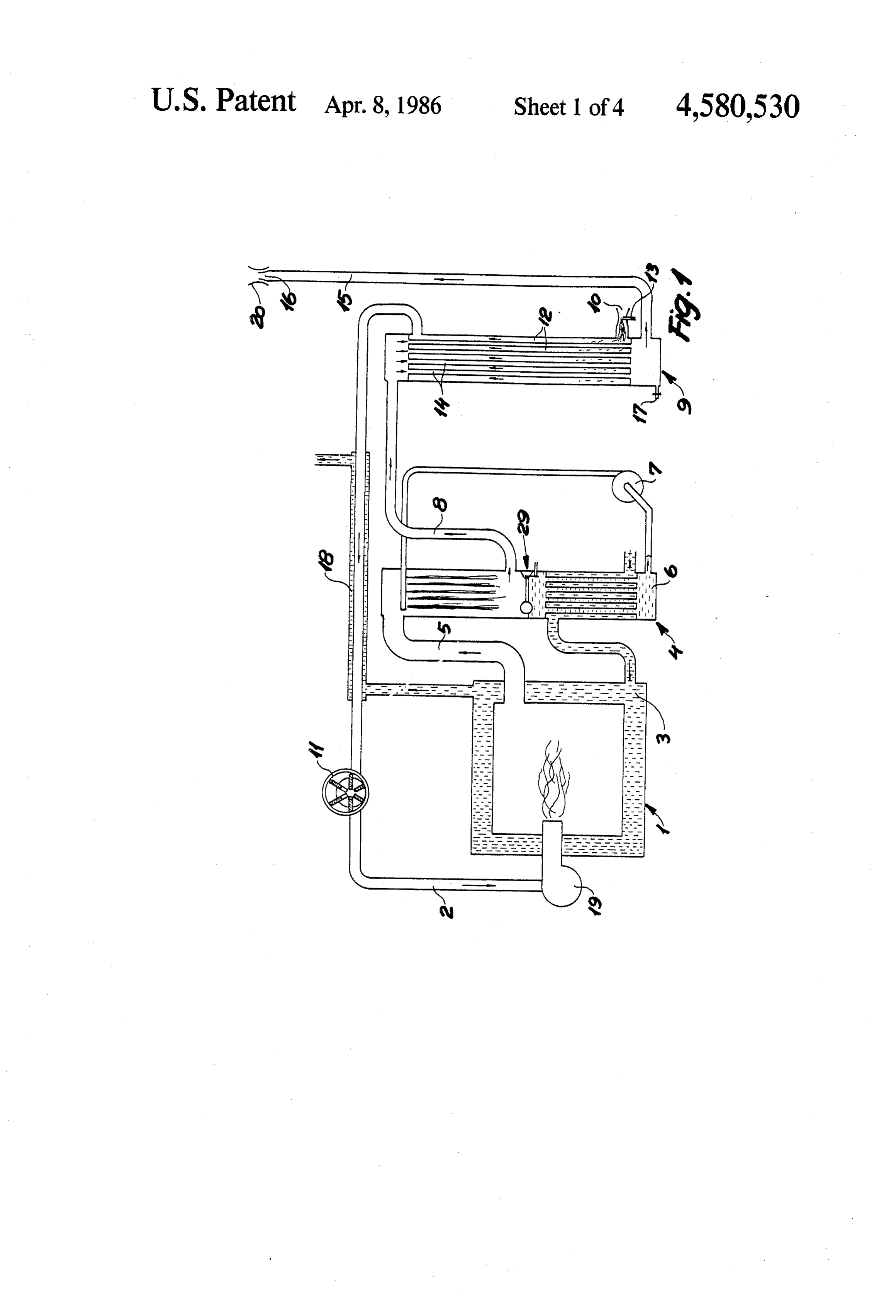
However, a liquid ring pump lends itself particularly ticularly, the combustion air is drawn in through a nar well to installation after the furnace, as stated in claim row duct 10 by means of a pump 11, which, in the 13. The reason is that the liquid ring pump has the spe shown embodiment, is a generally known rotary pump. cial advantage of being insensitive to hammering be The flow resistance of the duct 10 and the characteris cause the condensates separated in the pump are accom 5 tics of the pump are so adapted that the pressure in the modated in the liquid ring forming part of a circulation portion 12 of the heat exchanger 9, where the liquid circuit for the pump in a known manner. The latter evaporates, is considerably reduced with respect to the circulation circuit may be in heat exchanging relation atmospheric pressure. The vaporizable liquid, called ship with the firing plant or another heat consuming water in the foregoing, is supplied through a nozzle 13 object, cf. the features stated in claim 14. O which terminates in the narrow duct 10 so that the Preferably, as stated in claim 15, flue gas washer liquid is supplied according to the same principle as in a means known perse are positioned between the furnace carburetter. The low pressure in the heat exchanger and the liquid ring pump so that the flue gas is cooled portion 12 causes accelerated evaporation of liquid in and cleaned before entering the liquid ring pump. Then the combustion air, resulting in a very low temperature the pump will transport fewer kilogrammes of water 15 for additional cooling of the flue gas which flows from and fewer liters of air so that it consumes less waste above and down through a heat exchanger portion 14 power. As a water circuit will typically be involved, the before being discharged to the atmosphere through a liquid ring pump will be called water ring pump in the flue 15.
following. In the embodiment shown, the flue 15 terminates in a It will be appeciated that the plant may comprise 20 narrow opening 16, which causes such a great pressure several pumps and/or flue gas washer means depending drop that the flue gas pressure in the heat exchanger upon whether it will be economically worth while mak portion 14 is noticeably higher than the atmospheric ing the control of the plant more sophisticated with pressure, thus accelerating, in a known manner, the respect to its capacity. The control is no part of the condensation of the flue gas (condensates may be dis invention, but it will be appreciated that e.g. the flow 25 charged through an outlet 17 in the bottom of the heat resistance through the stated inlet and discharge open exchanger 9). It will then be readily understood that the ings may be adjustable in accordance with the pump system shown in FIG. 1 operates like an ordinary heat power and in dependence upon the amount of fuel con pump system, which explains the unsurpassed efficiency sumed per unit of time. over the prior art. A comparison is made with the heat The invention will be explained more fully by the 30 pump system because the combustion air drawn in following description of some embodiments with refer through the duct 10 serves as a carrier for a coolant in ence to the drawing, in which the form of the water from the nozzle 13, and the rotary FIG. 1 shows a first embodiment of a plant according pump 11, which serves as a compressor, creates a low to the invention, while pressure in the heat exchanger portion 12, which thus FIGS. 2-4 show modified embodiments of the plant 35 serves as the evaporator of a heat pump system. The according to the invention. corresponding condensator is formed by the heat ex The firing plant shown in FIG. 1 comprises a furnace changer porton 14, so that the temperature levels of the 1 which receives combustion air through a duct 2. The combustion air and flue gas temperature levels are "arti generated thermal energy is given off partly to a circu ficially' pumped to levels which cause an unprece lating heating medium 3 and is partly contained in the dented low flue gas discharge temperature with the flue gas passing from the furnace through a duct 5 into consequent high efficiency of the firing plant. a flue gas washer 4. Flue gas washers are known perse, In the embodiment of FIG. 1 a pressure increase will and it will therefore be readily understood that another take place through the pump 11, which involves the risk medium 6 is circulated by means of a pump 7 to create of the liquid vapour in the combustion air condensing a mist of liquid in the upper part of the flue gas washer, 45 between the pump 11 and the furnace 1. This is avoided which provides effective cooling of the flue gas and by means of a jacket type heat exchanger 18 through suspension of soot particles in the medium 6, so that the which the heated medium 3 flows so that the combus flue gas is both cooled and cleaned before passing tion air is superheated. The thermal energy spent on this through a duct 8 to an additional heat exchanger 9. It is not lost as it is passed directly to the furnace together appears that the heating medium 3 flows through a heat 50 with the combustion air.
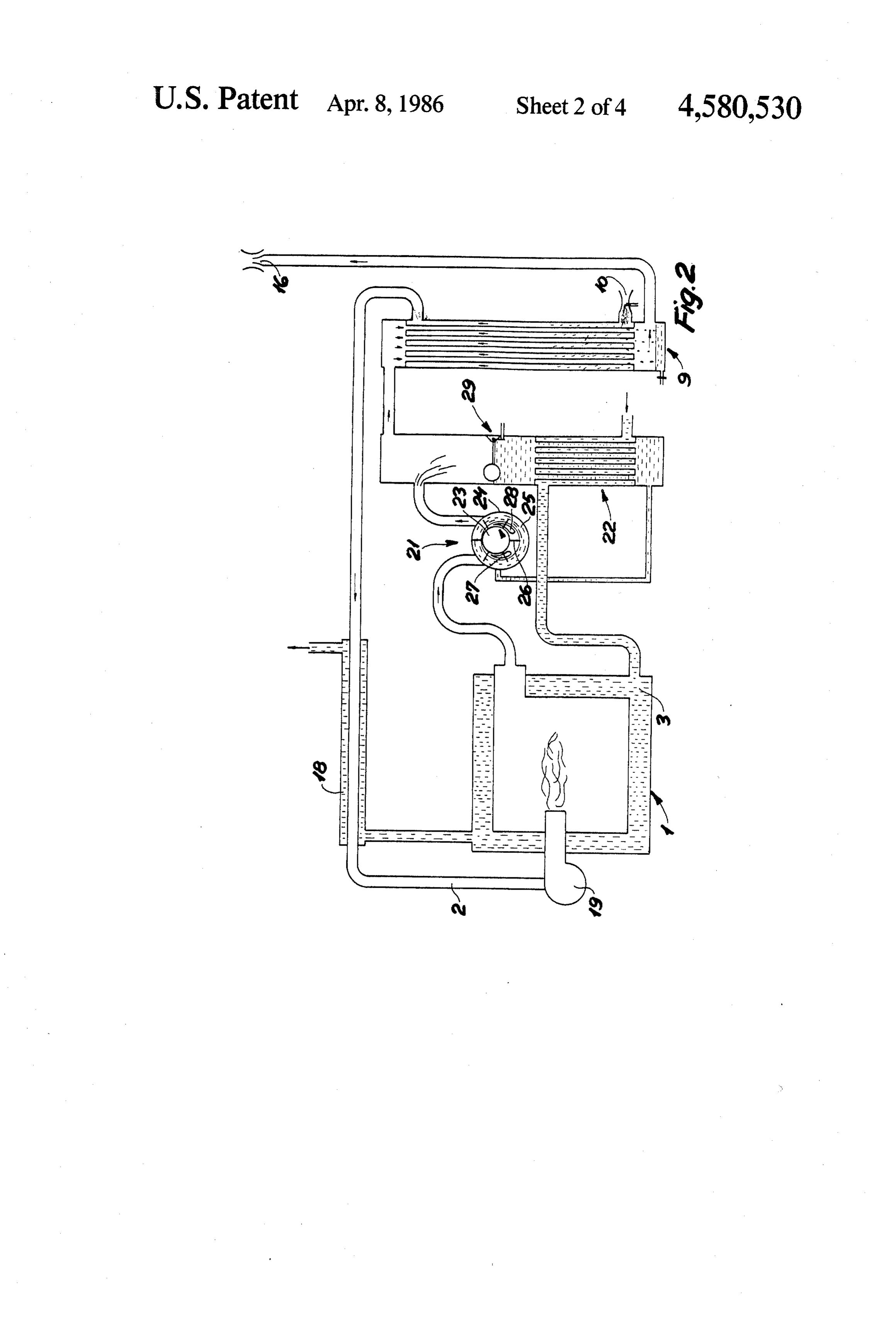
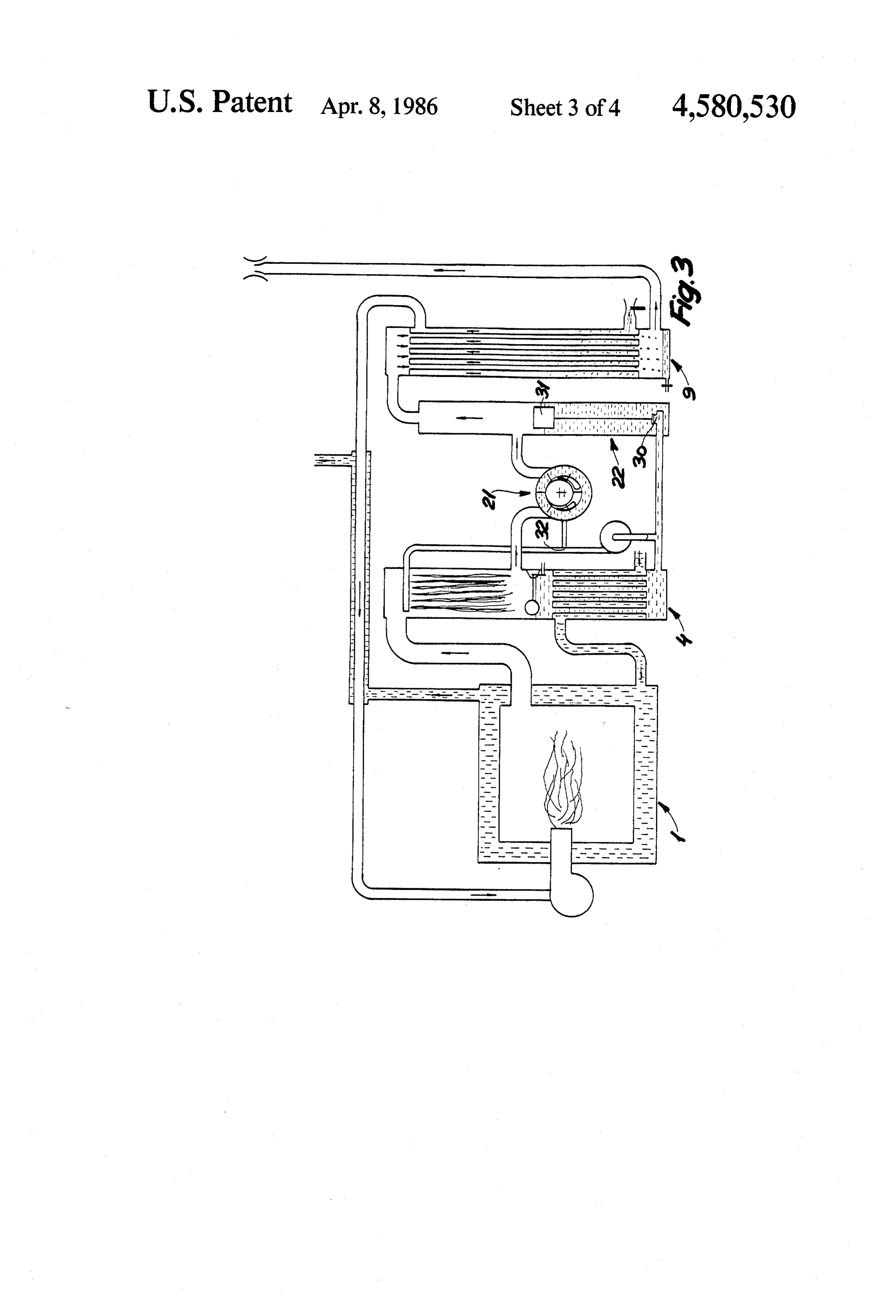
exchanger disposed in the lower portion of the flue gas The reference numeral 19 symbolizes a burner which washer 4 so that the thermal energy is transferred to this may correspond to a known oil burner with an associ heating medium. Usually, the heat exchanger at the ated blower. Owing to the pressure conditions de bottom of the flue gas washer is connected to e.g. the scribed, the blower can easily be omitted so that an oil return line of a radiator system so that the flue gas tem 55 injection nozzle will be sufficient. On the other hand, perature in the duct 8 is slightly greater than the return owing to the effective condensation of the flue gas, the temperature of the radiator system. system of the invention is particularly suitable for the However, one of the objects of the invention is to firing of moist solid fuel, such as straw or wood chips, obtain a significantly lower flue gas temperature before and in such cases the reference numeral 19 should be the flue gas is discharged to the atmosphere. taken to include feed means for such fuels. The additional cooling of the flue gas is provided in According to the invention, neutralizing and/or cata the heat exchanger 9. As mentioned earlier, it is not lyzing additives may be added to the water which is unknown to transfer thermal energy from the flue gas to introduced through the nozzle 13. Such additives may the combustion air, but, according to the invention, a be intended for neutralizing the sulfate combustion significantly more efficient heat transfer and thus colder 65 products and/or serving as catalysts for the conversion flue gas is obtained by the creation of a negative pres of the combustion products to substances easily separa sure in the portion of the exchanger 9 where vaporiz ble from the medium 6. As the additives are effectively able liquid evaporates in the combustion air. More par dispersed in the flame of the furnace, an even and com 8 plete neutralization is obtained so that very few acid designated by 4. The advantage of inserting the flue gas residues will be left in the flue gas. To additionally washer 4 in FIG. 3 is that the flue gas is cooled and protect the heat exchanger 9 against corrosion, the flue cleaned considerably before being drawn into the water gas is conducted from above and downwards, as men ring pump 21. Then, with respect to before, the water tioned earlier; this flow direction can easily be provided 5 ring pump will rotate fewer solid particles, and it will because of the positive pressure in the heat exchanger convey fewer liters of flue gas per unit of time so that portion 14 in connection with the discharge of the flue the losses in the water ring pump in FIG. 3 are lower gas at 16. When the flue gas is discharged, it expands, than they would have been in the embodiment shown in and in connection with guide plates 20 it is rapidly FIG. 2. In FIG. 3 the by-pass container 22 of the water dispersed in a large volume of air so that "acid showers' O ring pump is connected to the flue gas washer 4 through are excluded. a valve 30 controlled by a float 31. This arrangement is FIG. 2 shows another embodiment of the plant of the necessary because of the pressure difference between invention where the parts whose mode of operation the flue gas washer and the by-pass container, as caused corresponds to what is explained in connection with by the water ring pump 21. The supply of liquid to the FIG. 1 have the same reference numerals as in FIG. 1. 5 water ring is taken from a T-member 32 on the riser pipe The essential difference between the embodiment of to the top of the flue gas washer 4. FIG. 1 and the embodiment of FIG. 2 is that to the end In association with the embodiment shown in FIG. 3, of providing the desired pressure conditions in the heat an example will be given of some working conditions in exchanger 9 the pump is positioned in the flue and con the firing plant, it being supposed that combustion air is sists of a water ring pump 21 with an associated by-pass 20 drawn in at 10 with 4° C. and 80% relative humidity. container 22. Correct dimensioning of the throttle With a 25% excess of air, the enthalpy will be about 69 means 10, 16 and of the pump characteristics provides kcal per kg of burned oil. About 620 g of water per kg the desired working conditions, e.g. as described in the of burned oil are added in the heat exchanger 9, and the preceding paragraph. Because of the location of the air and water mixture is heated in the heat exchanger to pump 21, the superheater 18 is not strictly necessary but 25 about 30 C, causing all the added water to convert to is still preferred so that local cooling in the duct 2 does vapour phase as the pressure in the heat exchanger 9 is . not give rise to condensation of the added water vapor. e.g. 0.6 atmosphere. The enthalpy of the intake air is The changed location of the pump also means that a now about 600 kcal per kg of burned oil. A pressure of negative pressure exists in the furnace of FIG. 2. e.g. 1.4 atmospheres is obtained in the heat exchanger The principle of a water ring pump is known and will 30 portion 12 by means of the pump 21, and it is assumed therefore just be explained briefly. A rotor 23 is driven that the flue gas passed to the heat exchanger portion 12 eccentrically in the direction of the arrow in a rotor has a temperature of 45 C. and a water content of about housing 24, the centrifugal force creating a rotary liquid 850 g per kg of unburned oil corresponding to an en ring 25, preferably water, so that expanding and con thalpy of about 680 kcal per kg of burned oil. The flue tracting chambers are formed between the water ring 35 gas leaving the heat exchanger9 typically has a temper and rotor blades 26, said chambers communicating with ature of 14 C. and a water vapour content of 125 g of an inlet opening 27 and a discharge opening 28 for flue water per kg of burned oil (which is about one tenth of gas, respectively. In this embodiment the water ring 21 the water content in normal flue gases) and an enthalpy serves both as a flue gas washer and a primary flue gas of about 130 kcal per kg of burned oil. With these nu cooler. Excess pump water, which is heated and has merical examples the efficiency of the firing plant will absorbed soot particles, are ejected into the by-pass be between 99 and 100% of the upper calorific value. container 22, whose bottom accommodates a heat ex When the flue gas expands in the atmosphere, its rela changer for the heating medium 3 like the heat ex tive humidity falls from 100% to about 75%. changer in the bottom of the flue gas washer 4 in FIG. The embodiment of FIG. 4 differs from the embodi 1. Owing to the flue gas condensate, the amount of 45 ment of FIG.3 only by the provision of two pumps, viz. liquid in the by-pass container 22 continues to increase, the water ring pump 21 and a rotary pump 11 which and an overflow valve 29 is therefore provided (this was mentioned in connection with FIG. 1. The use of valve is also present in FIG. 1 for the same reason). two pumps of course provides a greater drive effect and A water ring pump offers several advantages when greater pressure differences, but also more freedom used for this special purpose. First, it can create a pres 50 with respect to the distribution of pressure through the sure difference which is sufficient for the invention, and firing plant. The plant may e.g. be so designed that the secondly it is insensitive to hammering which destroys absolute pressure in the furnace 1 is approximately must compressors when a mixture of liquid and gas is equal to the atmospheric pressure so that an ordinary employed. Finally, the powerful turbulence provides an existing furnace may easily be provided with the above efficient heat exchange between the flue gas and the 55 mentioned means for the achievement of the great effi water ring as well as the excess water which is ejected ciency which is characteistic of the plant, also when into the container 22. On the other hand, the water ring energy losses in the additional pump or pumps are taken pump has a slightly lower efficiency than ordinary com into consideration.
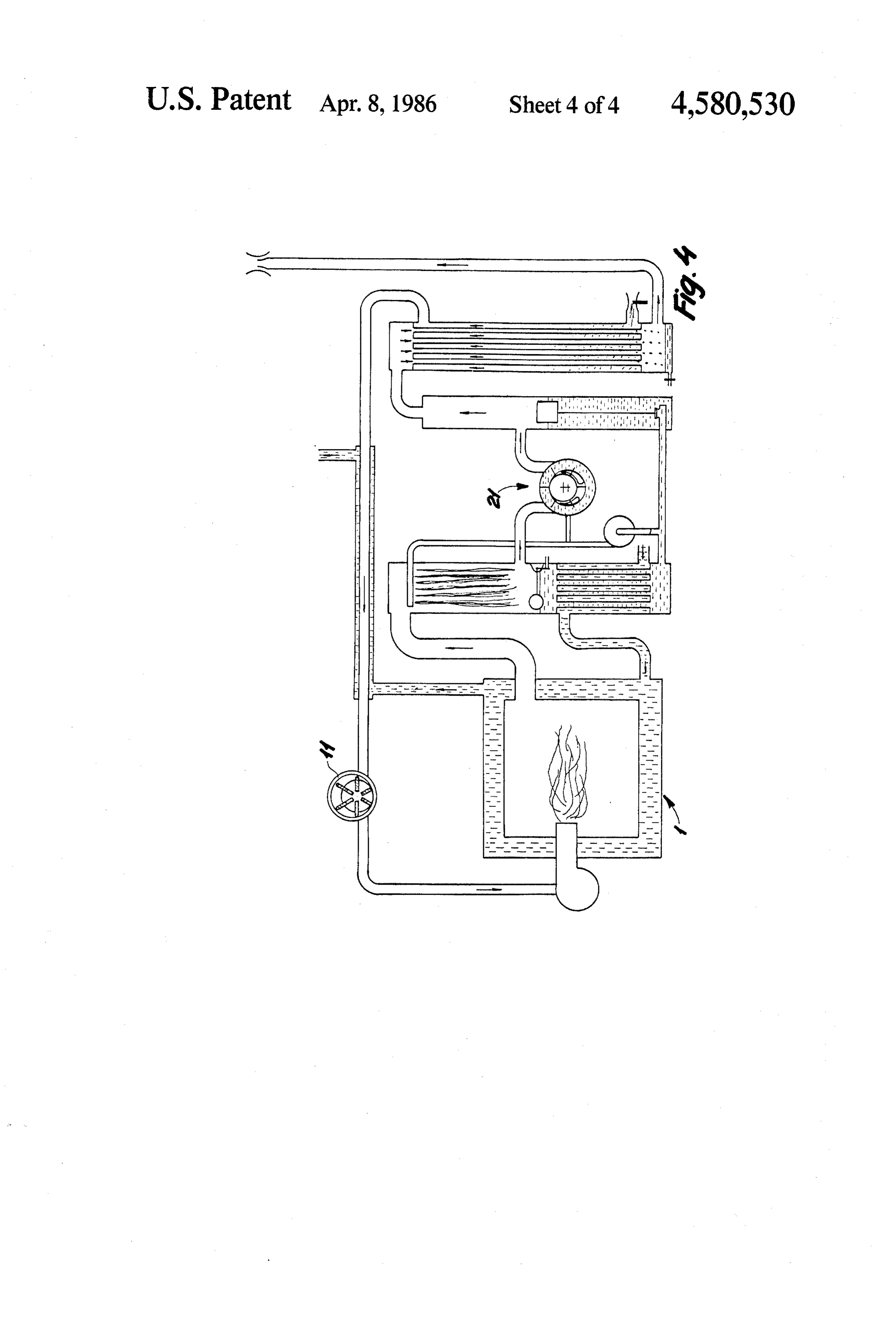
pressor because of the mechanical losses in the liquid I claim:
transport. However, these losses may be reduced, e.gby 601. A method in the operation of a firing plant of the means of the embodiment shown in FIG. 3. type comprising a combustion furnace and heat ex The embodiment of FIG. 3, too, contains parts which changer means which at least comprise a heat ex have been described in the foregoing and are therefore changer with a first portion through which the combus given the same reference numerals. The embodiment of tion air flows, and a second portion which is separated FIG. 3 differs from the one explained in connection 65 from the first portion and through which the flue gas with FIG. 2 by the provision between the furnace 1 and flows for transfer of thermal energy from the flue gas of the water ring pump 21 of a flue gas washer 4 of the the furnace to the combustion air, wherein a vaporiz same type as the one shown in FIG. 1, which was also able liquid is added to the combustion air, characterized 9 by reducing the combustion air pressure in the first changer to sufficiently below atmospheric pressure to portion of the heat exchanger to sufficiently below enhance the evaporation of said liquid, and further com atmospheric pressure so that the first portion of the heat prising a pressure outlet in the direction of the second exchanger serves as a low pressure evaporator for the portion of the heat exchanger.
said liquid. 5 8. A plant according to claim 7, characterized by a 2. A method according to claim 1, characterized by venturi duct disposed between the inlet opening and the admixing the liquid with additives resulting in readily first portion of the heat exchanger and containing a separable combustion products during combustion. nozzle to discharge the liquid. 3. A method according to claim 1, characterized by 9. A plant according to claim 7, characterized in that increasing the flue gas pressure in the second portion of 10 the air pump means are placed between the first and the heat exchanger to above atmospheric pressure so second portions of the heat exchanger and are designed that the second heat exchanger portion serves as a high to generate a positive pressure in the second portion of pressure condenser for the flue gas. the heat exchanger.
4. A method according to claims 1 or 3, characterized 10. A plant according to claim 7, characterized by air by establishing the said pressure conditions so that the 15 pump means provided between the furnace and the pressure in the combustion furnace is adjustable with second portion of the heat exchanger to increase the respect to the pressure of the surroundings.
5. A method according to claim 1, 2 or 3 character flue gas pressure in the second portion of the heat ex changer in which the flue gas condenses.
ized by superheating the wetted combustion air.
6. A method according to claim 3, characterized by that11.the A plant according to claim 7 or 9, characterized in air pump means comprises a rotary pump which using a liquid ring pump to compress the flue gas.
7. A firing plant for performing the method of claim is placed between the first portion of the heat exchanger 1 and comprising a combustion furnace, a gas flow duct and the furnace.
system including an inlet opening and a discharge open 12. A plant according to claim 7, characterized in that ing for combustion gas and flue gas, respectively, heat 25 additional heat exchanger means are provided between exchanger means in said gas flow duct system and com the first portion of the heat exchanger and the furnace prising at least a heat exchanger with a first portion to superheat the combustion air.
connected between the inlet opening and said combus 13. A plant according to any of claims 7-10 and 12, tion furnace, and a second portion separated from the characterized by a liquid ring pump disposed between first portion and connected between the discharge 30 the furnace and the second portion of the heat ex opening and the furnace, and means for adding a liquid changer.
to the combustion air admitted into said gas flow duct 14. A plant according to claim 13, characterized by system via the inlet opening, said heat exchanger being additional heat exchanger means through which the operable to transfer thermal energy from the flue gas to ring pump liquid and circulation water, respectively, the combustion air, partly because the liquid added to 35 flow to distribute thermal energy from the plant. the combustion air evaporates in the combustion air and 15. A plant according to claim 13, characterized in condenses in the flue gas, characterized by air pump that flue gas washer means known perse are provided means comprising a suction inlet in the direction of the between the furnace and the inlet opening of the liquid first portion of the heat exchanger to reduce the com ring pump.
bustion air pressure in the first portion of the heat ex 40 a
Provenance
- Collection
- Patents citing this work
- Pages
- 9
- Method
- pdftotext (the PDF's own text layer) + pdftoppm 300dpi page scans
- Patent office record
- patents.google.com →
- Source
- Google Patents citing-documents table
- Assignee
- Olrik Henrik G
- Published
- 1986-04-08
- Transcribed from
- patentimages.storage.googleapis.com →