

patent · US4602615A
Solar wall panel
29 July 1986
Text
Page 1bibliographic recordscan →
United States Patent (19)
Clegg
(54) SOLAR WALL PANEL
76 Inventor: John E. Clegg, 2320 Keystone Dr.,
Orlando, Fla. 32806
(51) Int. Cl. ................................................. F24J 2/18 52 U.S. Cl. ..................................... 126/439; 126/440 Field of Search ................................ 126/439, 440
2.881,654 4/1959 Toffolo ..................................... 88/ 2,882,784 4/1959 Toffolo ..................................... 88/ 4,057,048 11/1977 Maine ... ... 126/440 4,277,148 7/1981 Clegg ... ... 350/432 4,325,612 4/1982 Clegg ... ... 350/432 4,333,713 6/1982 Clegg ... ... 350/432 4,492,438 l/1985 Clegg .................................. 350/432
4,521,085 6/1985 Clegg .................................. 350/432 Primary Examiner-Carroll B. Dority, Jr.
A construction member comprising a curved metal frame having a conical beam concentrator, an exterior plate glass cover, and an interior plastic wall panel mounted therein and serving as the circular wall panel of a circular building. The concentrator receives an incipient beam of diffused sunlight and refracts a con centrated annular beam onto a conical mirror which reflects a convergent lateral beam inward to the center of the building. A circular conical beam concentrator located in the crawl space refracts the beam twice more and emits a concentrated beam onto a heating element through which domestic hot water circulates.
1 Claim, 5 Drawing Figures
Drawings
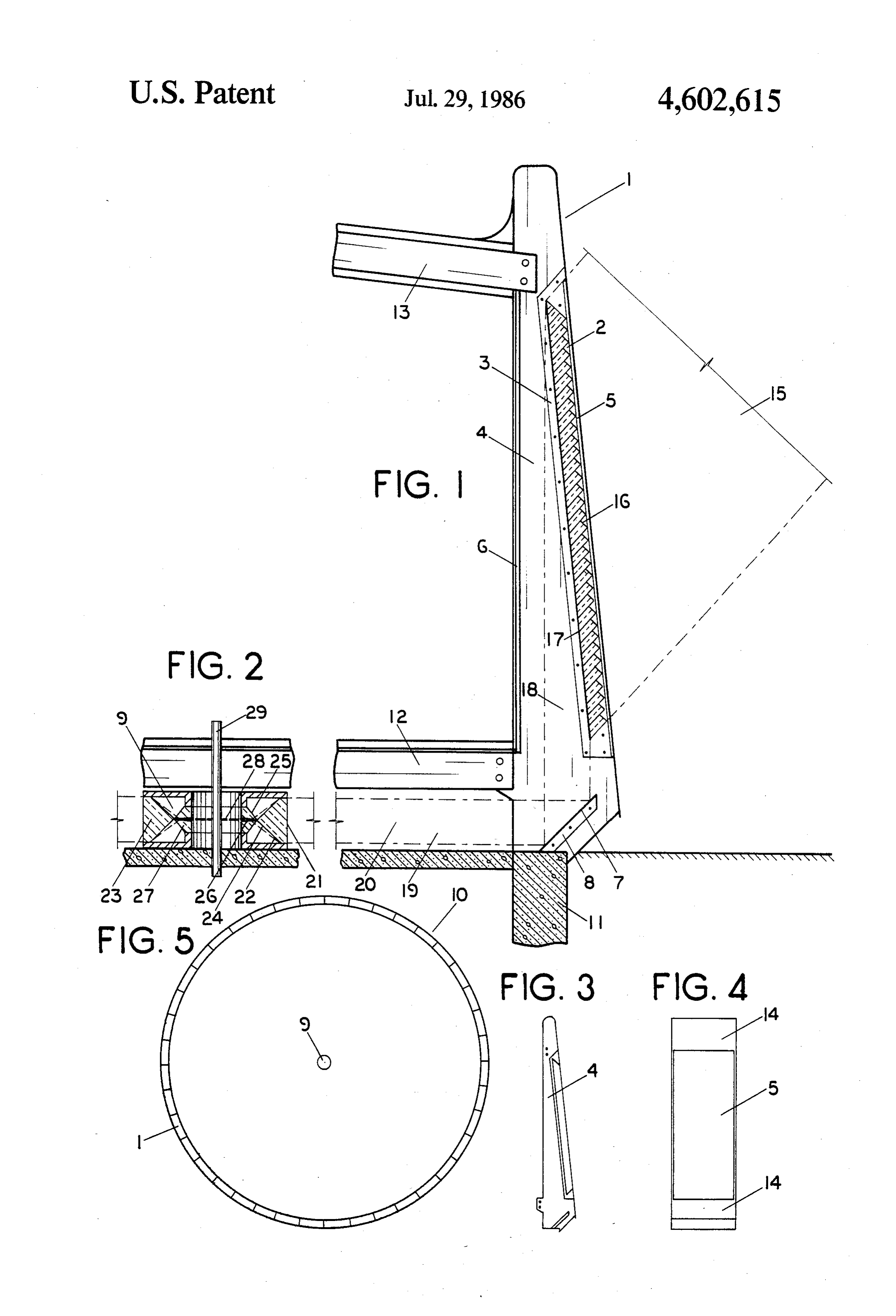
FIG. 4 is a elevation of the front plate and plate glass
FIG. 5 is a plan view of forty solar wall panels form
Page 2drawing sheetscan →
Page 3scan →
FIG. 4 is a elevation of the front plate and plate glass
SOLAR WALL PANEL cover of a solar wall panel.
FIG. 5 is a plan view of forty solar wall panels form
BACKGROUND ing the wall of a circular building, with the circular The code designation of the optical lenses of the solar 5 conical beam concentrator shown in the center. wall panel is 2RT-L-RT:C (R-refracting section of a DESCRIPTION component lens, T-transmitting section of a compo nent lens, L-reflecting section of a mirror, and The term solar wall panel used herein refers to a C-concentrating stage lens). 2RT refers to the circular 10 system comprising a wall panel and its constituent parts conical beam concentrator in the center of the building, including the circular conical beam concentrator L refers to the conical mirror, RT refers to the conical mounted in the center of the building. beam concentrator mounted in the panel forming the FIG. 1 is an elevation of the solar wall panel 1 show exterior wall of the building, and C refers to the func ing the annular frusto-conical beam concentrator 2 tion of the lenses. mounted on bracket 3 inside side plate 4, exterior plate Prior art includes three conical beam concentrators 15 glass cover 5, interior plastic wall panel 6, concave which receive annular incipient beams of direct sunlight conical mirror 7 mounted on bracket 8, and the circular and emit concentrated circular whole beams (U.S. Pat. conical beam concentrator 9 (FIG. 2) mounted in the Nos. 2,881,654 and 2,882,784 by Toffolo and 4,325,612 center of the circular building 10 (FIG. 5). The near by Clegg) and four conical beam concentrators which side plate (not shown) has been excluded from the receive whole incipient beams of direct sunlight and drawing in order to expose the interior parts to view. emit concentrated whole beams (U.S. Pat. Nos. Panel 1 rests on foundation wall 11 and supports floor 4,277,148; 4,333,713; 4,492,438; and 4,521,085 by joists 12 and rafters 13 as shown. Clegg). None of these concentrators can receive con FIG. 4 is an elevation of panel 1 showing front plate vergent conical incipient beams and emit concentrated 25 14 and plate glass cover 5.
convergent lateral beams in the horizontal plane, this FIG. 5 is a plan view of circular building 10 con being the distinctive patentable feature of the disclo structed of forty panels. The diameter of the building is Sule. fifteen and a half meters (fifty-one feet). A circular Concurrent art includes three conical beam concen building is adapted to the use of annular conical beam trators which receive convergent conical beams of dif 30 concentrators, and it has a cost advantage over rectan fused sunlight and emit circular whole beams parallel to gular buildings in that it encloses twenty seven percent the vertical axis; Conical Beam Concentrator RT:C, Ser. more floor space than a rectangular building with walls No. 634,155, filed 7/25/84, now U.S. Pat. No. of the same length.
4,575,196, Conical Beam Concentrator RT:C, Ser. No. Referring to the ray diagrams of FIGS. 1 and 2, con 651,015, filed 9/17/84, now U.S. Pat. No. 4,577,938, and 35 vergent conical incipient beams 15 of diffused sunlight Conical Beam Concentrator RT:C, Ser. No. 641,274, is received and transmitted by thirty-four inset convex filed 8/16/84. conical sections 16 and refracted by concave conical The circular conical beam concentrator mounted in section 17, forming concentrated annular beam 18, the crawl space in the center of the building in the Beam 18 is reflected by concave conical mirror 7, Subject disclosure is identical to a concentrator in an 40 forming convergent lateral beam 19 which is projected application filed earlier; Circular Comical Beam Concen parallel to the horizontal plane through crawl space 20 trator 2RT:C, Ser. No. 654,297, filed 9/25/84, now toward the center of the building. abandoned. Beam 19 is transmitted by cylindrical section 21 and The solar panel wall disclosed herein is one of three refracted and emitted by two opposed concave conical inventions in which the elements of conical optics and 45 sections 22 of outer component lens 23 of concentrator architecture are combined to produce circular buildings 9, forming two concentrated convergent conical beams which are heated by diffused solar radiation. The other 24.
two inventions are; Conical Diffused-Sunlight Solar Beams 24 are transmitted by two opposed convex Panel, Ser. No. 762,896, filed 8/6/85, with an annular conical sections 25 and refracted and emitted by two roof-mounted conical lens, and Wal-Mounted Conical 50 opposed concave conical sections 26 of inner compo Beam Concentrator, Ser. No. 770 126, filed 8/28/85, with nent lens 27, forming concentrated convergent lateral a conical lens mounted to the lower three courses of a beam 28 which strikes heating element 29. concrete-block wall. Heating element 29 is a vertical hot water pipe which The areas of the incipient beams of these units are absorbs the heat of beam 28 and transfers the heat to measured in hundred of thousands of square centime 55 water circulating through the pipe. Excess hot water ters, and the concentrated lateral beams which provide treated during the day is stored in a large underground the heat to the heating elements are less than ten square tank and circulated throughout the building as a source centimeters in area. Beam reductions of this magnitude of heat during the night.
are necessary because the heat content of diffused radia The heat content of diffuse solar radiation is low, and tion is low. 60 this means that a relatively large incipient beam must be DRAWINGS received and reduced in size to a relatively small con centrated beam with an intensity high enough to pro
FIG. 1 is an elevation of the solar wall panel. vide sustained heat to the heating element throughout FIG. 2 is an elevation of the circular beam concentra the daylight hours. The beam concentrators of the solar tor mounted in the crawl space in the center of the 65 wall panel achieve the required reduction in size both building. by refraction (reduction in the vertical plane) and by FIG. 3 is an elevation of a side plate of the solar wall convergence (reduction in the horizontal plane) as panel. shown in the table below:
Page 4scan →
Incident brm. Means of Reduced bm
Beam area - cm reduction area - cm incipient bm. 15 667,000 Refraction 122,000 Conv. at. bm. 19 22,000 Convergence 6,380 Conv. lat. bm. 19 6,380 Refraction 496
The area of 667,000 cm2 of incipient beam 15 is pro- 10 duced by only thirty two of the total forty panels com prising the wall of the circular building. Eight lenses must be excluded to make room for doors and windows. The reduced beam area of 9.4 cm2 is the area of con centrated lateral beam 28 at the point of contact with 15 heating element 29, the means of reduction being both refraction and convergence, with the latter being not listed in the table but included in the total reduction in beam size:
The number of windows needed in the house is less 20 than ordinarily required, because the interior plastic wall panels 6 are translucent and admit a soft light that would be excluded by solid walls.
I claim
1. A solar wall-panel heating system comprising in 25 general multiple segments of a frusto-conical beam con centrator mounted inside multiple wall panels of a cir cular building, and a circular conical beam concentrator mounted in the center of the building; the beam concen- 30 trators serving as means of receiving a beam of diffused solar radiation and of reducing the beam to a small concentrated convergent lateral beam projected onto a central heating element; and comprising in particular; a solar wall panel (1) having two vertical metal side 35 plates (4) occupying radial planes of the circular building (10), having an exterior plate glass cover (5) mounted to the outer edges of the side plates (4), having a front metal plate (14) mounted to the outer edges of the side plates (4) above and below 40 exterior plate glass cover (5), and having an inte rior plastic wall panel (6) mounted to the inside edge of side plates (4), side plates (4) having an elongate bracket (3) for mounting the frusto-conical beam concentrator, 5 side plates (4) having a bracket (8) on which is mounted a concave conical mirror;
a segment of an annular frusto-conical beam concen trator (2) mounted on elongate brackets (3) and having a series of inset convex conical sections (16) which receive and transmit a convergent conical incipient beam (15) of diffused solar radiation, and having a concave conical section (17) which re fracts and emits incipient beam (15), forming con centrated annular beam (18); said concave conical mirror (7) mounted on angular brackets (8) and having a reflective surface which reflects concen trated annular beam (18), forming convergent lat eral beam (19) which is projected parallel to the horizontal plane toward the center of circular building (10);
a circular conical beam concentrator (9) mounted in the center of circular building (10) and having an outer component lens (23) with a cylindrical sec tion (21) which receives and transmits convergent lateral beam (19), and with two opposed concave conical sections (22) which refract and emit con vergent lateral beam (19), forming two concen trated convergent conical beams (24); and having an inner component lens (27) with two opposed convex conical sections (25) which receive and transmit convergent conical beams (24), and with two opposed concave conical sections (26) which refract and emit convergent conical beams (24), forming concentrated convergent lateral beam a heating element (29) comprising a vertical hot water pipe mounted inside inner component lens (27) of circular conical beam concentrator (9) so as to intercept concentrated convergent lateral beam (28) and absorb the heat thereof.
Provenance
- Collection
- Patents citing this work
- Pages
- 4
- Method
- pdftotext (the PDF's own text layer) + pdftoppm 300dpi page scans
- Patent office record
- patents.google.com →
- Source
- Google Patents citing-documents table
- Assignee
- Clegg John E
- Published
- 1986-07-29
- Transcribed from
- patentimages.storage.googleapis.com →