

patent · US4608920A
Electroplasmolyzer for processing vegetable stock
2 September 1986
Text
Page 1bibliographic recordscan →
United States Patent (19) 11 Patent Number: 4,608,920 Scheglov et al. (45) Date of Patent: Sep. 2, 1986 54 ELECTROPLASMOLYZER FOR Field of Search ................. 99/352,451, 358, 483, PROCESSENG VEGETABLE STOCK 99/484, 646 R, DIGS. 11-14; 426/234-236,
76 Inventors: Jury A. Scheglov, ulitsa 288, 291, 293,295, 289; 210/748; 204/186, 302, Pryanishnikova, 5/3, kv. 80; Nikolai 304 P. Koval, ulitsa Pryanishnikova, 5/2, (56) References Cited kv. 89; Leonid A. Furer, ulitsa
Aerodromnaya, 7/2, kv. 18; Sergei Y. U.S. PATENT DOCUMENTS
Zargarian, ulitsa Chernyshevskogo, 337,334 3/1886 Jones et al. ........................... 99/451 76, kv. 14; Anatoly A. Skimbov, 1,162,213 11/1915 Bloom. . 99/451 X Beltsky pereulok, 2, kv. 2, all of 4,457,221 7/1984 Geren ............................... 99/516 X Kishinev, Vladimir G. Belik, ulitsa
Bogatyrskaya, 18, kv. 189; Boris N. FOREIGN PATENT DOCUMENTS
Zharik, ulitsa Garmatnaya, 33/1, kV. 100094 Mi954 U.S.S.R. .
17, both of Kiev; Andrei Y. 428.737 5/1974 U.S.S.R. .
Papchenko, prospekt Mira, 24, kv. 72, Primary Examiner-Timothy F. Simone
Kishinev; Filipp G. Ryabinsky, ulitsa Attorney, Agent, or Firm-Fleit, Jacobson, Cohn & Price Parkovaya, 32, kv. 4, Nikolaev;
Alexandr S. Sergeev, deceased, late of 57 ABSTRACT
Simferopol; by Galina A. Sergeeva, An electroplasmolyzer for processing vegetable stock administrator, bulvar Lenina, 2a, kV. comprises a housing which accommodates therein elec 25, Simferopol, all of U.S.S.R. trodes provided with a plane surface of contact with vegetable stock being processed, said electrodes con 21 Appl. No.: 491,169 nected to a power supply. Adjacent electrodes in each pair thereof are connected to different phases of the power supply. The use of the herein disclosed electro 22 Filed: May 3, 1983 plasmolyzer in a production line for primary processing of vegetable stock results in an increased efficiency of pressing equipment and higher yield of juice from vege Int. Cl. ................................................ A23L 3/00 table stock.
52 U.S. C. ........................................ 99/451; 99/483;
99/516; 219/288; 426/283; 426/244 14 Claims, 9 Drawing Figures
Drawings
Page 2drawing sheetscan →
Page 3drawing sheetscan →
Page 4drawing sheetscan →
Page 5scan →
being processed are distributed uniformly over the en
ELECTROPLASMOLYZER FOR PROCESSING tire inner surface of the housing while adjacent elec VEGETABLE STOCK trodes in each pair thereof are connected to different phases of the power supply.
TECHNICAL FIELD It is expedient that some electrodes provided with a The present invention relates to the processing of plane surface of contact with vegetable stock being foodstuffs and, more particularly, it relates to an elec processed be positioned on two opposite walls of the troplasmolyzer for processing vegetable stock. housing across the entire width of said walls while other The present invention may be employed in produc electrodes provided with a plane contact surface of tion lines for primary processing of fruit, vegetables and 10 identical shape and having chamfered ends of the side of root crops to prepare juice, pulp or plasmolyzed shav the inlet opening of the housing be positioned between ings. said former electrodes on two other walls of the hous
Background of the invention
ing and spaced from each other at a distance equal to 0.2-0.4 width of one of the electrodes positioned across
Known in the prior art is an electroplasmolyzer (cf., 15 the entire width of the walls, a gap being formed be U.S.S.R. Inventor's Certificate No. 428,737, IntCl2 A tween the end faces of the electrodes of identical shape, 23 N 1/00, 1972) for processing vegetable stock, com said gap being equal to 0.2-0.4 width of one of the prising a rectangular housing with inlet and outlet open electrodes positioned across the entire width of the ings, accommodating thereinside two perforated plate housing wall.
electrodes mounted in parallel with the longitudinal It is possible that some square-shaped electrode hav axis. Provided between side walls of the housing and ing a plane surface of contact with vegetable stock the perforated electrodes are narrow spaces designed to being processed be positioned on three walls of the be filled with juice fed by gravity. housing while other electrodes with a plane contact Said prior art electroplasmolyzer fails to ensure com 25 surface of identical shape be positioned on a fourth wall plete and uniform processing of comminuted vegetable at a distance between the electrodes equal to 0.2-0.4 stock and provides no possibility of uniformly loading width of the square-shaped electrode, the ends of the the power supply phases.
Closest of all to the herein disclosed electroplasmo electrodes of identical shape being chamfered on the side of the inlet opening of the housing.
lyzer bit its technical essence is a multielectrode electro It is likewise expedient that the distance between the plasmolyzer (cf., U.S.S.R. Inventor's Certificate No. 30 electrodes 100.094, Cl. 53 K 1/01) comprising a rectangular hous d/A=N-2,be with selected on the basis of the relationship ing made of dielectric, on whose top and bottom walls Emins sV/As Emax,due regard for the inequality rod electrodes are located uniformly and flush with the wall surface, said electrodes extending at right angles to where d-width of the wall to which the electrodes of iden the longitudinal axis of the housing. The housing is 35 tical shape are attached, provided with an inlet opening for vegetable pulp and A-distance between the electrodes, with an outlet opening for the discharge of electrically N-total number of electrodes, processed stock. V-voltage of the power supply, Such an apparatus provides for uniform loading of the power supply phases and uniform density of electric 40 Emin, Emax-minimum and maximum values of elec current across the electrodes while the process of elec tric field intensity, respectively. troplasmolysis proceeds without overheating the prod It is further desirable that the distance between the uct being processed. electrodes be selected on the basis of the relationship The mass of raw stock moves by gravity in an in d/A=N-1, with due regard for the inequality clined electrode channel since no provision is made in 45 wheremins V/AS SEmax, the apparatus for pulp-pushing means. This results in a pulsating movement of vegetable stock in the electrode d-width of the wall to which the electrodes of iden channel, while the small area of the contact surface of tical shape are attached, electrodes along the generatrix of round rods fails to A-distance between the electrodes, ensure uniform processing of comminuted mass and 50 N-total number of electrodes, affects the yield of juice therefrom. Moreover, the V-voltage of the power supply, travel rate of the mass does not agree with the current Emin, Ema-minimum and maximum values of elec density across the electrodes and depends upon the tric field intensity, respectively. angle of inclination of the electroplasmolyzer housing. It is expedient that the ends of the electrodes of iden 55 tical shape be chamfered on the side of the inlet opening
BRIEF DESCRIPTION OF THE INVENTION of the housing at an angle of 30-60 to the longitudinal It is the object of the present invention to develop an axis of the housing while the outlet opening of the hous electroplasmolyzer capable of ensuring a uniform elec ing be provided with a regulating valve. tric processing of comminuted vegetable stock, improv It is desirable that the electrodes having a plane sur ing the cell permeability of the latter and increasing the face of contact with vegetable stock being processed be yield of juice therefrom. distributed uniformly over the entire inner surface of The problem of the invention is solved owing to the the housing provided with a movable casing and includ fact that, in an electroplasmolyzer for processing vege ing at least three sections, the cross-sectional area of table stock, comprising a housing which has an inlet each subsequent section being greater than that of the opening and an outlet opening and accommodates 65 preceding section, with some electrodes having a plane thereinside electrodes connected to a power supply, contact surface in each one of the housing sections according to the present invention, the electrodes hav being positioned on two opposite walls at right angles to ing a plane surface of contact with vegetable stock the longitudinal axis of the housing and their number 6 being divisible by three and other electrodes having a The electroplasmolyzer of the invention needs no plane contact surface in each one of the housing sec continuous supervision and is reliable in operation. The tions being positioned in parallel with the longitudinal electric power consumption does not exceed 2 kW/h axis of the housing on two other walls and the number per ton of vegetable stock.
of said latter electrodes being divisible by three, and Small overall dimensions of both the electroplasmo that two rows of jet injectors be provided between said lyzer for fruit processing and its power supply facilitate latter electrodes in two sections of smaller cross-sec their transportation by air through considerable dis tional areas. tances.
It is possible that the jet injectors be connected to BRIEF DESCRIPTION OF THE DRAWINGS different phases of the power supply. 10
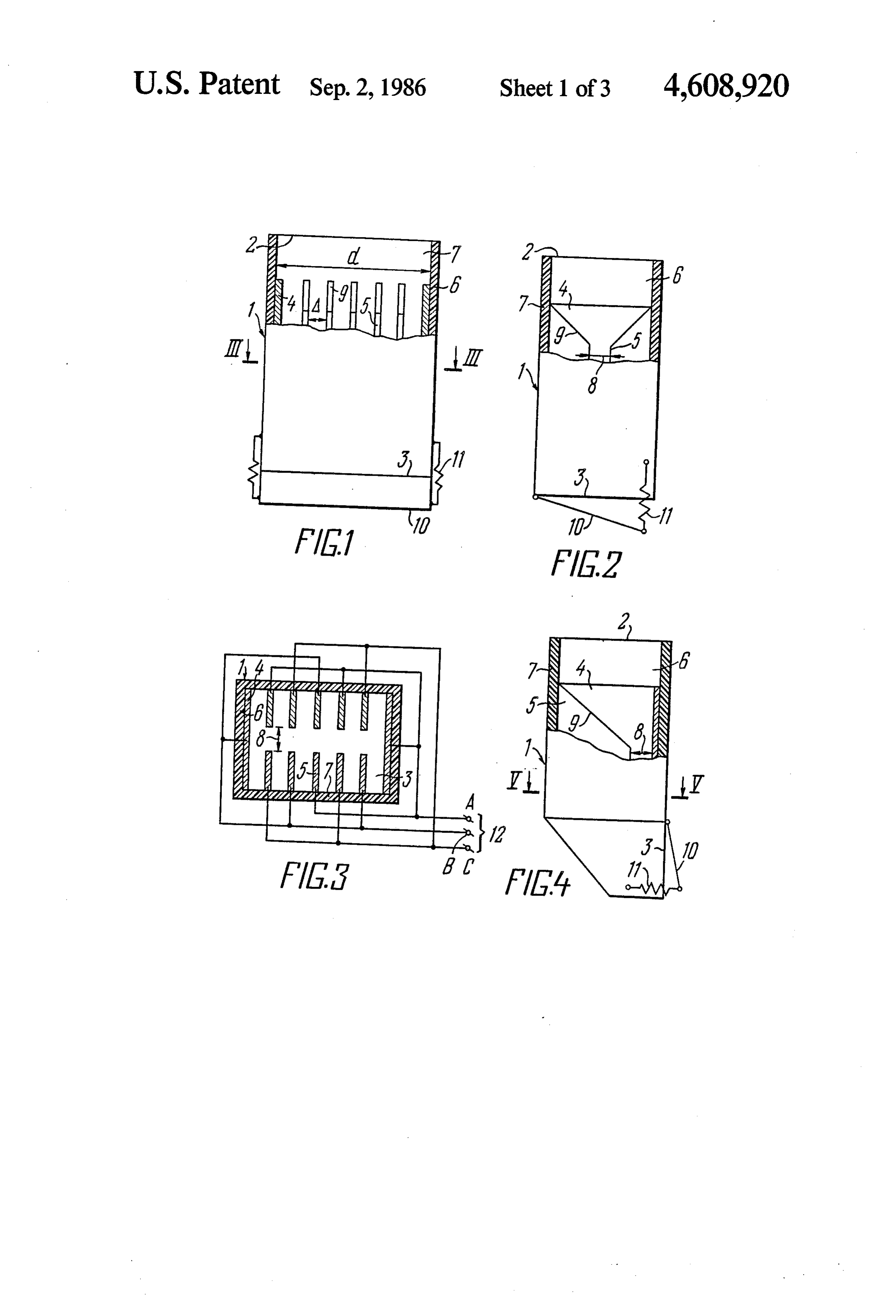
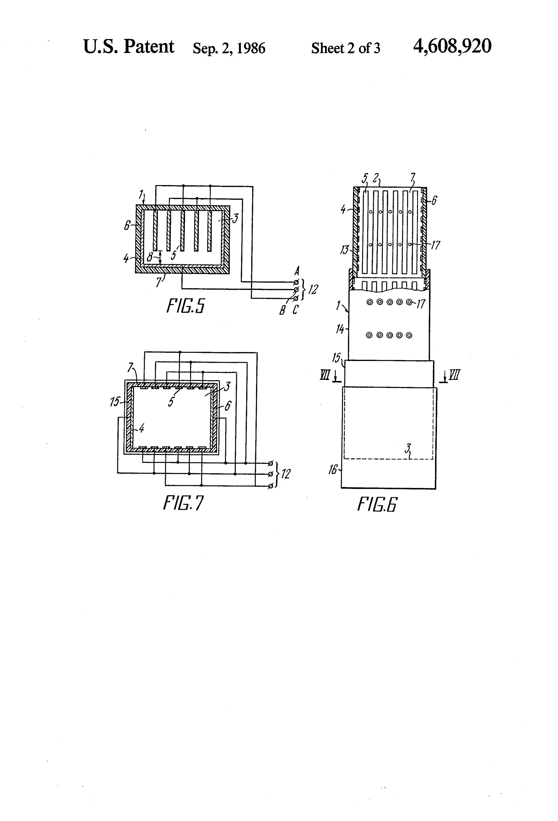
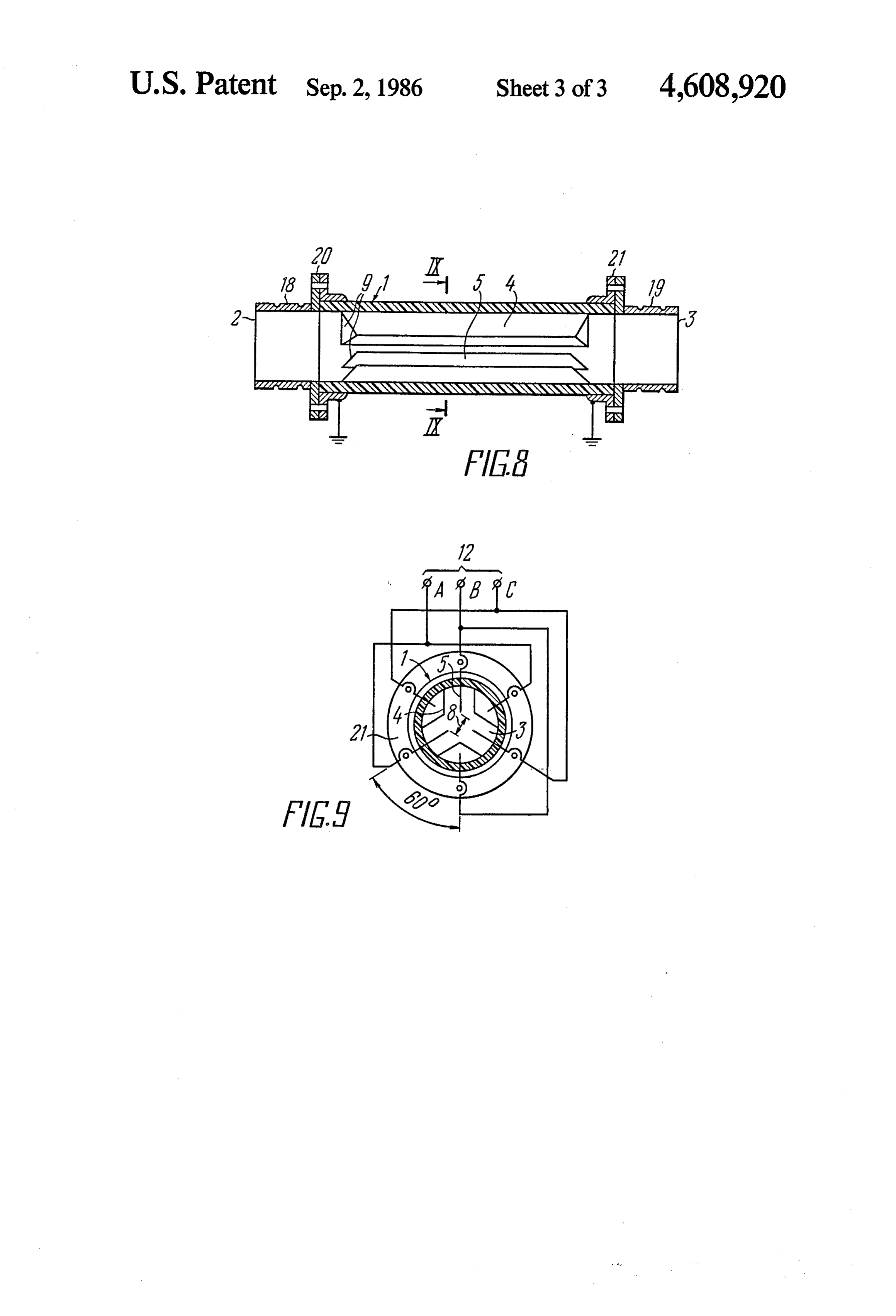
It is expedient that the sector-shaped electrodes have The invention will be made apparent upon consider ing a plane surface of contact with vegetable stock ing the following detailed description of an exemplary being processed be uniformly arranged at an angle of embodiment thereof, with due references to the accom 120 to each other on the inner surface of the housing panying drawings in which:
and that the electrodes having a plane contact surface 15 FIG. 1 is a general view of an electroplasmolyzer for be mounted equidistantly between said former elec processing vegetable stock, having a rectangular hous trodes at an angle of 120” to each other, the housing ing with two rows of electrodes of identical shape, being cylindrical in shape, and that the electrodes on the according to the present invention; side of the inlet and outlet openings have their ends FIG. 2 is a side view of an electroplasmolyzer with a chamfered with respect to the longitudinal axis of the regulating valve on the outlet opening of the housing, housing, a gap between the end faces of the electrodes according to the present invention; m with plane contact surface being equal to the distance FIG. 3 shows a cross-section of the electroplasmo between the sector-shaped electrodes and electrodes lyzer taken along the line III-III of FIG. 1, and a with plane contact surface. circuit diagram of electrode connection to the power The use of the herein disclosed electroplasmolyzer in 25 supply, according to the invention; a production line for primary processing of apples to FIG. 4 is a side view of an electroplasmolyzer for juice results in the maximum destruction of the cyto processing vegetable stock, having a rectangular hous plasm of cells which were left intact as a result of me ing with a single row of electrodes of identical shape chanical comminution of stock. This is accompanied by and with a regulating valve on the outlet opening of the an increase of the efficiency of batch-operation pressing 30 housing, according to the invention; equipment and by a rise in the yield of apple juice of up FIG. 5 shows a cross-section of the electroplasmo to 5%. When processing machine-harvested black ash lyzer, taken along the line V-V of FIG. 4, and a circuit berry and tomatoes, the yield of juice rises by up to diagram of electrode connection to the power supply, 10%. according to the present invention; The electrodes have a plane contact surface posi 35 FIG. 6 is a general view of an electroplasmolyzer for tioned in parallel with each other and are uniformly processing vegetable stock, with a housing having three located along the inner surface of the housing to ensure sections and a movable casing, according to the present a reliable electrical contact with the vegetable stock. invention;
This avoids creating in this case, an increase in hydrau FIG. 7 is a cross-section of the electroplasmolyzer, lic resistance. The availability of 30” to 60' chamfers on 40 taken along the line VII-VII of FIG. 6, with a circuit the electrode ends located on the side of the inlet open diagram of electrode connection to the power supply, ing of the housing ensures uniformity in filling the according to the present invention;
chamber with vegetable stock, as a result of which the FIG. 8 is a longitudinal sectional view of an electro uniformity of processing vegetable stock with electric plasmolyzer with a cylindrical housing, according to current is improved, which, in term also results in a rise 45 the present invention; and in the yield of juice. FIG. 9 shows a cross-section of the electroplasmo Owing to an increased yield of juice, the apple marc lyzer, taken along the line IX-IX of FIG. 8, with a contains a smaller amount of moisture and, therefore, circuit diagram of electrode connection to the power the fuel consumption when drying them is reduced by supply, according to the present invention. 0.1 while the rate of drying increases. In the electroplas SO DETAILED DESCRIPTION OF THE molyzer, the vegetable pulp is processed in the course INVENTION of fractions of a second, with the sugars, acids and vita mins of the starting product being fully converted to Referring now to FIG. 1 of the accompanying draw ju1ce. ings, a rectangular housing 1 of the herein disclosed The electric processing is rather effective when pro 55 electroplasmolyzer is made of a dielectric and has an cessing the grape pulp and sugarbeet shavings. Isabella inlet opening 2 and an outlet opening 3. Positioned grapes after crushing are pretreated with ferments or inside the housing 1 in parallel with the longitudinal axis heat-treated for 12-48 hours; it is only after such pro thereof are some electrodes 4 and other electrodes 5, cessing that the must is extracted. This process involves having a plane surface of contact with vegetable stock considerable consumption of manual labor, the use of 60 being processed (not shown in the drawing). Two elec numerous containers and requires substantial working trodes 4 are attached to walls 6 across the entire width area. Upon electric processing of grapes, the gravity thereof while the electrodes 5 of identical shape are yield of must increases by up to 6%, and the process of attached to two other opposite walls 7. must extraction is continuous. The uniform distribution of the electrodes 5 inside the The electric processing of sugarbeet shavings pro 65 electroplasmolyzer housing 1 is provided for by the vides a possibility of improving the quality of diffusion relationship d/A=N-2, with due regard for the in juice, reduce the thermal energy consumption and in equality Emin SV/ASEmax, crease the sugar yield by 0.5%. where
Page 7scan →
Enin-minimum value of electric field intensity; One of the electrodes 4 is connected to phase A, with Enix -maximum value of electric field intensity; the first column of adjacent electrodes 5 connected to d-width of the wall 7 to which the electrodes 5 are phases B and C, the second column-to phases A and C, attached; the third column-to phases A and B, the fourth colum A-distance between the electrodes 5; n-to phases B and C, the fifth column-to phases A N-total number of the electrodes 4, 5; and C, and the second electrode 4-to phase B. The V-voltage. electrodes 4 and 5 are connected uniformly to all three The V/A ratio characterizes the value of electric field phases A, B and C.
intensity. Therefore, at values below 50 V/cm there is In view of the foregoing, the number of the elec observed a sharp increase of the amount of time re 10 trodes 4, 5 in the electroplasmolyzer is selected such quired for electric processing of vegetable mass, that it would be divisible by three, with each pair of whereas values above 400 V/cm can only be attained adjacent electrodes 5 connected to different phases A, with the aid of special transformer means for increasing B, C. It is therefore that twelve electrodes 45 are the voltage applied to the electroplasmolyzer. shown in FIG. 3, ten out of them being the electrodes 5. The minimum value of electric field intensity for flow 15 FIG. 4 illustrates an electroplasmolyzer with a single processing of vegetable stock is Emin =50 V/cm. The inlet row of the electrodes 5 (side view). The housing 1 has maximum value of electric field intensity, Emax=400 opening 2 and outlet opening 3 provided with the V/cm, is obtained from commercial-frequency a.c. regulating valve 10 and spring 11. Attached to opposite walls 6 of the housing 1 and to mains without the use of transformer means.
It follows from the relationship d/A=N-2 that the 20 one of the walls 7 is a square-shaped electrode 4 with plane contact surface. Electrodes 5 are attached to the distance between the electrodes 5 should be selected in the range of from 20 to 40 mm. For example, given the other wall 7 and, on the side of the inlet opening 2, have ends 9 chamfered at angles of 30-60 to the longitudi width of the wall 7 with the electrodes 5 of d=280 mm nal axis of the housing 1. The provision of chamfered and the distance between the electrodes 5 of A=40 mm, 25 ends the number of the electrodes 5 equals 280/40=7-2=5. matter9 from of the electrodes 5 precludes fibrous foreign accumulating on top end faces of said elec
A reduction of the distance between the electrodes 5 to trodes and facilitates the conveyance of such foreign a value less than 20 mm may result in the sticking of matter to the gap 8 formed vegetable mass between the electrodes 5 while an in and square-shaped electrodeby4theandrowequal of electrodes 5 crease of said distance to a value over 40 mm will re 30 width of the square-shaped electrode 4. quire higher values of electric field intensity which can FIG. 5 is a cross-sectional view of the electroplasmo only be attained with the aid of special transformer lyzer with a single row of electrodes 5 attached to the means increasing the voltage across the electroplasmo wall 7. As a result, the gap 8 is formed between the end lyzer. faces of the electrodes 5 and square-shaped electrode 4, FIG. 2 is a side view of the electroplasmolyzer hous 35 said gap being equal to 0.2-0.4 width of the square ing 1. The electrodes 5 attached to two opposite walls 7 shaped electrode 4.
to form a gap 8 have, on the side of the inlet opening 2, The uniform distribution of the electrodes 5 inside the ends 9 chamfered at an angle of 30-60 to the longitudi housing 1 of the electroplasmolyzer is ensured by ob nal axis of the housing 1. Should the angle of chamfer of serving the relationship d/A=N-1, with due regard the chamfered ends 9 be less than 30, foreign matter 40 for the inequality Emins V/ASEmax, such as leaf or straw particles may be retained on the where end face of the electrode 5, while an angle of chamfer d-width of the wall to which the electrodes 5 are over 60 would lead to a sharp reduction of the surface attached;
of the electroplasmolyzer electrodes 5. The gap 8 be A-distance between the electrodes 5; tween two rows of the electrodes 5 is equal to 0.2-0.445 N-total number of the electrodes 4, 5; width of one of the electrodes 4. The provision on the V-voltage of the power supply 12; outlet opening 3 of a regulating valve 10 with a spring Enin-50 V/cm, Emax=400 V/cm. 11 ensures delivery pressure and good contact of the Comminuted vegetable stock is fed continuously pulp (not shown in the drawing) with the electrodes 4, from a crusher to the electroplasmolyzer housing 1 to 5. 50 be processed between the electrodes 4 and 5 and in their FIG. 3 shows a cross-sectional view of the electro gap 8.
plasmolyzer with a circuit diagram of connections of The circuit diagram of connections of the electrodes the electrodes 4, 5. Attached to the walls 6 of the hous 4 and 5 is made three-phase, with the adjacent elec ing 1 are the electrodes 4, while two rows of the elec trodes 5 connected to different ones of the two phases A trodes 5 of identical shape are positioned on two other 55 and C of the power supply 12, and the square-shaped opposite walls 7. Provided between the rows of the electrode 4-to phase B. In so doing, there is ensured a electrodes 5 in the center of the housing 1 is the gap 8 uniform and more complete processing of vegetable equal to 0.2-0.4 width of one of the electrodes 4. The stock between the electrodes 4 and 5 since adjacent electric processing of vegetable stock is effected be electrodes 4, 5 in each pair thereof are connected to tween the end faces of the opposite electrodes 5 since different phases A, B, C of the power supply 12. It the latter are connected to different phases A, B, C of an should be noted that no deviations are permitted from a.c. power supply 12. A reduction of the gap 8 between the specified values of the angle of chamfer of the ends the electrodes 5 to a value below 0.2 width of the elec 9 of the electrodes 5 and of the gap 8, as in the case of trode 4 may lead to electric breakdown of the mass of the electroplasmolyzer shown in FIGS. 2 and 3. vegetable stock and, consequently, to nonuniform pro 65 FIG. 6 is a general view of an electroplasmolyzer cessing, while an increase of the gap 8 to a value in with inlet and outlet openings 2 and 3, rectangular hous excess of 0.4 width of the electrode 4 would lead to ing 1 including at least three sections 13, 14 and 15 and incomplete electric processing of vegetable stock. a movable casing 16.
Page 8scan →
Each one of the sections 13, 14, 15 has walls 6 with The electroplasmolyzer includes the dielectric hous electrodes 4 positioned at right angles to the longitudi ing 1 provided with inlet and outlet openings 2 and 3. nal axis of the electroplasmolyzer housing 1 and walls 7 Positioned on the inner surface of the housing 1 are with electrodes 5 positioned in parallel with the longitu three sector-shaped electrodes 4 between which there dinal axis of the housing. The electrodes 4 and 5 have a 5 are provided three electrodes 5 with plane contact sur plane surface of contact with vegetable stock being face spaced equidistantly from each other. The length processed. The cross-sectional area of the sections 14 is of the electrodes 5 is equal to that of the sector-shaped larger than that of the section 13 while the cross-sec electrodes 4. In so doing, the ends 9 of the electrodes 4, tional area of the section 15 is larger than that of the 5 are made chamfered at an angle of 45°-60° to the section 14. Such an expansion of the cross-sectional area 10 longitudinal axis of the housing 1 and form tapered of the electroplasmolyzer towards the bottom is caused portions designed to reduce the hydraulic resistance by the need to provide conditions for unobstructed upon the movement of pulp.
conveyance of comminuted vegetable stock in the form Provided on the inlet and outlet openings 2 and 3 of of shavings which interwine and form lumps readily, the electroplasmolyzer housing 1 are connecting pipes this possibly leading to the jamming of the narrow elec 15 18 and 19 coupled to the housing 1 by means of flange trode channel. joints 20 and 21; the latter flange joints are grounded. For regulating the surface over which the shavings The connecting pipes 18 and 19 serve to join the elec spread in a wide hopper of a diffuser (not shown in the troplasmolyzer, by means of a flexible hose, to a pulp drawing) upon their discharge from the housing 1 of the pump, or the electroplasmolyzer is directly built in a electroplasmolyzer via the outlet opening 3, use is made 20 metal pulp-conveying line with the aid of welded joints of the movable casing 16 displaceable along the longitu in the line section between the pump and press (not dinal axis of the section 15. shown in the drawing).
In addition, two rows of jet injectors 17 are posi FIG. 9 is a cross-sectional view of the electroplasmo tioned on the walls 7 in the sections 13 and 14 of the lyzer comprising the cylindrical housing 1, with a cir electroplasmolyzer between the electrodes 5, said jet 25 cuit diagram of connections of the electrodes 4 and 5 in injectors serving to inject liquid into shavings in order the case of a three-phase power supply 12. to provide for better contact of vegetable stock with the The sector-shaped electrodes 4 and the electrodes 5 electrodes 4 and 5, the number of electrodes 4, 5 in each are positioned on the inner surface of the electroplasmo one of the sections 13, 14, 15 being divisible by three. lyzer housing 1 at an angle of 120 to eah other and FIG. 7 is a cross-sectional view of the electroplasmo 30 equidistantly from each other, the gap 8 between the lyzer with a circuit diagram of connections of the elec edges of the electrodes 5 being equal to or less than the trodes 4, 5. Given the number of the electrodes 4 and 5 distance between the electrodes 5 and the sector-shaped divisible by three, their connection alternates between electrodes 4. A flange 21 is attached to the housing 1. three phases A, B, C of the power supply 12, thereby The circuit diagram of connections of the electrodes ensuring their uniform loading. 35 4 and 5 allows for the alternation of phases between the In the sections 13, 14, 15 of the electroplasmolyzer electrodes 5 with plane contact surface and sector housing 1, adjacent electrodes in each pair of the elec shaped electrodes 4. For example, the electrode 5 with trodes 4 and 5 positioned on the walls 6 and 7, as well as plane contact surface (top center) is connected to phase positioned one opposite each other on the opposite B, the sector-shaped electrode 4 which follows in a walls 7, are connected to different ones of the phases A, clockwise direction is connected to phase A, then the B, C of the power supply 12, the electrodes 5 and jet electrode 5 is connected to phase C, electrode 4-to injectors 17 on the wall 7 (FIG. 6) are likewise con phase B, electrode 5-to phase A and so on. All six nected to different ones of the phases A (FIG. 7), B and electrodes 4, 5 are uniformly distributed between the C of the power supply 12. three phases A, B and C of the power supply 12. The casing 16 (FIG. 6) is movable along the longitu 45 The electroplasmolyzer according to the present dinal axis of the section 15 of the housing 1 and, upon invention operates in the following manner. being adjusted at the required level, is secured in that Comminuted vegetable stock from, say, a disk position. crusher (not shown in the drawing) is fed to the housing The circuit diagram of connections of the electrodes 1 (FIGS. 1, 2, 3) of the electroplasmolyzer via the inlet 4 and 5 (FIG. 7) is made three-phase, with the elec 50 opening 2 and further delivered to the electrodes 4, 5 trodes 5 having a plane contact surface being positioned positioned equidistantly from each other and attached on the opposite walls 7 of the housing 1. They are con to opposite walls 6 and 7. In so doing, voltage from the nected (bottom row) from left to right-the first elec three-phase a.c. power supply 12 is applied to the elec trode 5 to phase A, the second electrode 5 to phase B, trodes 4 and 5, and the continuously moving vegetable the third electrode 5 to phase C, the fourth electrode 5 55 pulp is treated with electric current. The electric cur to phase A and so on. The electrodes 5 (top row) are rent simultaneously affects all of the vegetable cells left connected as follows: the first electrode 5 to phase C, intact after mechanical comminution of vegetable stock the second electrode 5 to phase A, the third electrode 5 and, owing to translatory vibration of ions, protein to phase B, the fourth electrode 5 to phase A and so on; coagulates in the cytoplasm, plasma bunches are formed the opposite electrodes 4 positioned on the walls 6 are 60 and channels for the outlet of cell juice. also connected to different phases, for example, those Foreign matter carried by the stock is moved over on the left-hand side-to phase B, and those on the the chamfered ends 9 of the electrodes 5 and, via the right-hand side-to phase A. The electrodes 4 and 5 are gap 8 formed by two rows of the electrodes 5, is deliv connected uniformly to all of the three phases A, B and ered together with electrically treated pulp to the outlet C. The jet injectors 17 (FIG. 6) are likewise alternately 65 opening 3 of the housing 1, to the regulating valve 10 connected to different phases A, B, C. whose expansion angle is adjusted by means of the FIG. 8 shows the electroplasmolyzer with a cylindri spring 11. The regulating valve 10 makes for the devel cal housing 1, in longitudinal section. opment of pulp delivery pressure inside the housing 1, 9 thereby eliminating voids in the pulp and ensuring a which affects the vegetable stock to destroy the cyto good contact of the pulp with the electrodes 4 and 5. plasm in the cells, thereby facilitating water diffusion at Adjacent electrodes 5, as well as electrodes 4, in each lower temperature and reducing considerably the tran pair thereof are connected to different phases A, B, C, sition of non-sugars to juice.
thereby ensuring a fuller and more uniform processing 5 Owing to sectional expansion of the housing 1, it is of the pulp and increased yield of juice. permitted to install the electroplasmolyzer at an angle The voltage from the power supply 12, applied to the of up to 45 to the vertical, whereby the apparatus of electrodes 4 and 5, is adjusted depending on the type the invention may be used in production lines somewhat and variety of the stock being processed. For instance, differing from each other due to possible changes in the summer apples are processed at lower voltage andau O position of production equipment.
tumn apples-at higher voltage. While so doing, the Adjacent electrodes 4 and 5 in the sections 13, 14, 15, efficiency of electroplasmolysis is increased. as well as the opposite jet injectors 17, are connected to Analogous is the process of plasmolysis in an electro different phases A, B, C of the power supply 12. In plasmolyzer featuring a somewhat different arrange addition, the electrodes 5 and the jet injectors 17 posi ment of the electrodes 4, 5 in the housing 1 (FIGS. 4, 5). 15 tioned on the same side are likewise connected to differ Comminuted stock from a disk crusher is fed to the ent phases A, B, C. The casing 16 is reliably grounded. housing 1 via the inlet opening 2. The pulp is distributed As a result, the process of electroplasmolysis of beet and between the square-shaped electrode 4 and identical like shavings in a flow is continuous. The electroplas electrodes 5 on the walls 6 and 7 of the housing 1. While molyzer of the invention is mounted above the hopper so doing, voltage from the power supply 12 is applied to 20 of a diffuser and regulates the beet delivery pressure the electrodes 4 and 5. The pulp comes in contact with therein; the electroplasmolyzer further makes for a the electrodes 4 and 5 to be subjected to the effect of considerable increase of cell permeability, reduction on electric current, which results in an increased cell per the diffusion juice temperature and improvement of meability of the pulp and higher yield of juice upon quality thereof.
pressing. 25 The electroplasmolyzer with cylindrical housing 1 In case fibrous foreign matter is introduced with the (FIGS. 8, 9) works in combination with a pulp pump stock and possibly deposit on the end faces of the elec (not shown in the drawing). Comminuted vegetable trodes 5, use is made of chamfered ends 9 provided in stock such as pulp is pump-fed to the housing 1 via the the electrodes 5 on the side of the inlet opening 2. Upon inlet opening of the connecting pipe 18 coupled to the movement of the pulp, foreign matter slides over the 30 electroplasmolyzer housing 1 by means of the flange chamfered ends 9 of the electrodes 5 to move down the joint 20. The pulp passes round the chamfered ends 9 of gap 8 and to the outlet opening 3. This ensures an unob the sector-shaped electrodes 4 and of the electrodes 5 to structed movement of the pulp being processed be be uniformly distributed between the electrodes 4, 5. tween the electrodes 4 and 5. The delivery pressure of While so doing, a.c. voltage from the power supply 12 the pulp inside the housing 1 is ensured by the valve 10 35 is applied to the electrodes 4, 5, and the continuously provided with springs 11. In so doing, the pulp gets moving pulp is subjected to electric processing. The compacted and reliable electric contact is formed be plasmolyzed pulp under pressure leaves the housing 1 tween the pulp and the electrodes 4 and 5, thereby through the outlet opening 3 of the connecting pipe 19 ensuring effective electric processing of the pulp and with flange joint 21 and delivered via pipeline to a drain increased yield of juice. The degree of pulp delivery or press (not shown in the drawing). The pulp process pressure is adjusted with the aid of the springs 11. ing takes place in a closed plasmolysis chamber inacces The electrodes 5 and the square-shaped electrode 4 sible to atmospheric oxygen, thereby ruling out the are connected to different phases A, B, C and, there sticking of vegetable stock to the electrodes 4, 5 and fore, all of the electrodes 4, 5 are working ones and the precluding the oxidation process. process of stock plasmolysis in the flow is continuous. 45 The number of the electrodes 4 and 5 of the electro The electrodes 5 inside the housing 1 provide for a large plasmolyzer is divisible by three and, therefore, they are surface of contact with vegetable stock being pro connected to three phases A, B, C of the power supply cessed, without restricting its flow area. This renders 12, which ensures a short-duration electric processing the electroplasmolyzer of the invention highly efficient of the pulp directly in the flow, the flow area of the and reliable in operation. 50 electroplasmolyzer housing 1 being enlarged owing to The electroplasmolyzer whose housing 1 (FIGS. 6, 7) the fact that the electrodes 5 are positioned between the includes sections 13, 14, 15 operates somewhat differ sector-shaped electrodes 4, whereby the surface of ently. Comminuted stock in the form of shavings is fed contact with vegetable stock being processed can be to the housing 1 via the inlet opening 2 of the section 13. enlarged and the apparatus capacity increased. The The shavings fill the inner space of the housing 1 in all 55 electric processing results in an improved permeability of the three sections 13, 14 and 15 and is distributed of cell tissue and higher yield of juice produced there between the electrodes 4 and 5 attached to the walls 6 from.
and 7. Then, the shavings go down by gravity and fill The herein disclosed electroplasmolyzer for process the casing 16 which assists in distributing the shavings ing vegetable stock wherein the electrodes 4, 5 are in the hopper of a diffuser (not shown in the drawing) in rationally positioned on the inner surface of the housing the production line. P 1 makes for a more complete processing of fruit, vegeta The shavings move in the housing 1 without obstruc bles and root crops which yield insufficient amount of tion because the constituent sections 13, 14 and 15 are juice and other nutritious substances without electric arranged in a pattern of increasing cross-sectional area. processing and retain too much moisture in the marc, as Also conducive to the development of a continuous 65 a result of which considerable amount of liquid fuel is flow are jet injectors 17 through which liquid is injected required for drying the marc. Using the electroplasmo for wetting the shavings. While so doing, a.c. voltage is lyzer of the invention, a 5-10% increase in the yield of applied to the electrodes 4 and 5 and the jet injectors 17, fruit and vegetable juice can be attained for the loss of 10 the minimum amount of electric power. The electro longitudinal axis of the housing and the number of plasmolyzer contains a divisible by three number of said some electrodes being divisible by three, electrodes 4, 5 connected to the power supply 12 having the rest of said plurality of electrodes in each of said three phases A, B, C. sections of said housing being located in parallel The herein disclosed electroplasmolyzer for process with the longitudinal axis of said housing on two ing vegetable stock is simple of design, compact, can be other walls of the housing and the number of the readily manufactured, provides for unobstructed pas rest of said plurality of electrodes being divisible by sage and good processing of vegetable stock, can be three, and readily assembled in a production line, is reliable and two rows of jet injectors being located in two of said safe in operation. It helps considerably increase the O sections having the smallest cross-sectional areas output and efficiency. and are located between said rest of said plurality What is claimed is: of electrodes.
1. An electroplasmolyzer for processing vegetable 5. An electroplasmolyzer for processing vegetable stock, said electroplasmolyzer comprising: stock according to claim 1 wherein a housing defining an inlet opening and an outlet 15 said housing defines a cylindrical shape, opening; some of said plurality of electrodes having a sector an inner surface of said housing; shape and a plane surface of contact with vegetable a three phase power supply; stock being processed, being arranged uniformly at a plurality of electrodes, each electrode of said plural 20 an angle of 120 to each other on the inner surface ity of electrodes including a terminal portion and a of said housing, planar surface for contacting said vegetable stock the rest of said plurality of electrodes having a plane being processed, said plurality of electrodes being contact surface being equidistantly located at an distributed on the inner surface of said housing and angle of 120 to each other between said sector being connected to said three phase power supply 25 shaped electrodes;
so that adjacent electrodes are connected to differ the distance between end faces of said rest of said ent phases of said three phase power supply; and plurality of electrodes having a plane contact sur an unobstructed passageway extending through said face being equal to the distance between said sec housing, said passageway being defined adjacent to tor-shaped electrodes and said rest of said plurality said terminal portions of said plurality of elec 30 of electrodes having a plane contact surface; and trodes. the rest of said plurality of electrodes having a plane 2. An electroplasmolyzer for processing vegetable contact surface and said sector-shaped electrodes stock according to claim 1, wherein at least two of said having on the side of said inlet and outlet openings plurality of electrodes are located on two opposite walls of said housing, ends chamfered with respect to the of said housing and extend across the entire width of 35 longitudinal axis of said housing. said walls, the rest of said plurality of electrodes being 6. An electroplasmolyzer for processing vegetable of identical shape having chamfered ends located on the stock according to claim 2, wherein said distance be side of said inlet opening of said housing and being tween said rest of said plurality of electrodes is deter located between said at least two electrodes, and the mined by the formula d/A=N-2, and Emin SV/- rest of said plurality of said electrodes having an end ASEmax where face mounted on one of two other walls of said housing d-width of said housing wall to which said rest of and being spaced at a distance between each other equal said plurality of electrodes of identical shape are to 0.2-0.4 width of one of said at least two electrodes attached, extending across the entire width of one said opposite A-said distance between said rest of said plurality of housing walls, and a gap formed between opposing end 45 electrodes, faces of the rest of the plurality of electrodes of identical N-total number of said rest of said plurality of elec shape being equal to 0.2-0.4 width of one of said at least trodes, two electrodes. V-voltage of said three phase power supply, 3. An electroplasmolyzer for processing vegetable Emin-minimum value of electric field intensity, stock according to claim 1 wherein one of said plurality 50 Ema-maximum value of electric field intensity. of electrodes having a U shape is located on three walls 7. An electroplasmolyzer for processing vegetable of said housing and a remainder of said plurality of stock according to claim 2, wherein the rest of said electrodes being of identical shape and having an end plurality of electrodes are chamfered at an angle of face located on a fourth inner wall of said housing form 30-60 to the longitudinal axis of said housing and a a gap defined between a free end face of the remainder 55 regulating valve is located at said outlet opening of said of the electrodes and the crosspiece of said U shape housing.
electrode equal to 0.2-0.4 width of one of the legs of the 8. An electroplasmolyzer for processing vegetable U shape electrode, the ends of the remainder of said stock according to claim 3, wherein said distance be plurality of electrodes being chamfered on the side of tween the remainder of said plurality of electrodes is said inlet opening of said housing. 60 determined by the formula d/A=N-1, and Ennis V/- 4. An electroplasmolyzer for processing vegetable As Emax, where stock according to claim 1 further comprising: Emin-minimum value of electric field intensity; a movable casing for said housing, Emax-maximum value of electric field intensity; the housing including at least three sections aligned in d-width of said housing wall to which the remain progressively increasing cross sectional area, 65 der of said plurality of electrodes of identical shape some of said plurality of electrodes in each of said are attached;
sections of said housing being located on two oppo A-distance between said remainder of said plurality site walls of said housing at right angles to the of electrodes;
Page 11scan →
N-total number of said remainder of said plurality of regulating valve is located at said outlet opening of said electrodes; housing.
V-voltage of said three phase power supply. 12. An electroplasmolyzer for processing vegetable 9. An electroplasmolyzer for processing vegetable stock according to claim 8 wherein the remainder of stock according to claim 3, wherein the remainder of 5 said plurality of electrodes are chamfered at an angle of said plurality of electrodes are chamfered at an angle of 30-60 to the longitudinal axis of said housing and a 30-60 to the longitudinal axis of said housing and a regulating valve is located at said outlet opening of said regulating valve is located at said outlet opening of said housing.
housing.
10. An electroplasmolyzer for processing vegetable 10 13. An electroplasmolyzer for processing vegetable stock according to claim 4 wherein said two rows of jet stock according to claim 6, wherein Emin is equal to 50 injectors are connected to different phases of said three V/cm and Ena is equal to 400 V/cm. phases of said power supply. 14. An electroplasmolyzer for processing vegetable 11. An electroplasmolyzer for processing vegetable stock according to claim 8, wherein the value for Ein stock according to claim 6 wherein the rest of said 15 is equal to 50 V/cm and the value for Ena is equal to plurality of electrodes are chamfered at an angle of 400 V/cm.
30-60 to the longitudinal axis of said housing and a
Provenance
- Collection
- Patents citing this work
- Pages
- 11
- Method
- pdftotext (the PDF's own text layer) + pdftoppm 300dpi page scans
- Patent office record
- patents.google.com →
- Source
- Google Patents citing-documents table
- Assignee
- Scheglov Jury A
- Published
- 1986-09-02
- Transcribed from
- patentimages.storage.googleapis.com →