

patent · US4611577A
Black-water solar disk
16 September 1986
Text
Page 1bibliographic recordscan →
United States Patent (19)
Clegg
(54) BLACK-WATER SOLAR DISK
76 Inventor: John E. Clegg, 2320 Keystone Dr., Orlando, Fla. 32806
Int. Cl. ................................................. F24J 2/24 52 U.S. Cl. .................................... 126/444; 126/450;
4,136,670 1/1979 Davis .................................. 126/440
Primary Examiner-Larry Jones
A flat circular plate glass window and a conical circular metal disk mounted below the window so as to form an expansion chamber through which a black-dye solution of water and alcohol circulates. Water enters the cham ber through a 1 mm peripheral gap between the win dow and disk and exits through a vertical pipe located at the center of the chamber 15 mm below the window. The heated water expands outward against the tapered walls of the chamber and deflects in the direction of flow, thereby increasing the rate of flow.
1 Claim, 3 Drawing Figures
Drawings
Page 2drawing sheetscan →
Page 3scan →
The interior height of the expansion chamber 9 in the
BLACK-WATER SOLAR DISK center is 15 mm.
Window 2 is horizontal, and disk 3 is inclined 5 from
Prior art is limited to clear-water ponds and poolsBlack dye is added to water to render the water opaque to the transmission of solar radiation, and alco which store the heat of solar radiation and transfer the hol is added to prevent freezing during inoperative heat to domestic water circulating through pipes sub stages.
merged in the ponds and pools. In operation cool water enters the system through There is no prior art featuring black-water and a O four inlet tubes 6. The water circulates around inlet tapered expansion disk such as disclosed herein. manifold 10 and enters the expansion chamber 9 Concurrent art includes the Black-Water Solar Collec through peripheral gap 11.
tor, Ser. No. 727,938, filed Apr. 26, 1985, by this inven The water has been preheated by inlet tubes 6 which tor. In this invention domestic household water circu receive radiation from the bottom of disk 3 and which lates through expansion tubes mounted inside a tank of 15 are enclosed in housing 8, by flange plate 5 which is standing solar-heated black water. exposed at its outer edge to solar radiation, and by annu lar metal plate 4.
SUMMARY The water begins to boil as it passes inward and ab sorbs heat directly from solar radiation. Expansion
The objects of this invention are to provide a passive 20 chamber solar heating system in which the heat of solar radiation plate 4, and 9 is 3 mm thick just inside the annular metal is absorbed directly by black water and to provide a window 2 and the water expands both upward against the system in which the expansion of heated water is used as in the directiondownward against the disk 3 and deflects of flow. The water continues to boil as a means of circulating the water through radiant ceiling it moves inward, and there is deflection off both win panels. 25 dow 2 and disk 3 despite the increased dimensions of the The primary source of heat is by direct absorption of expansion chamber 9.
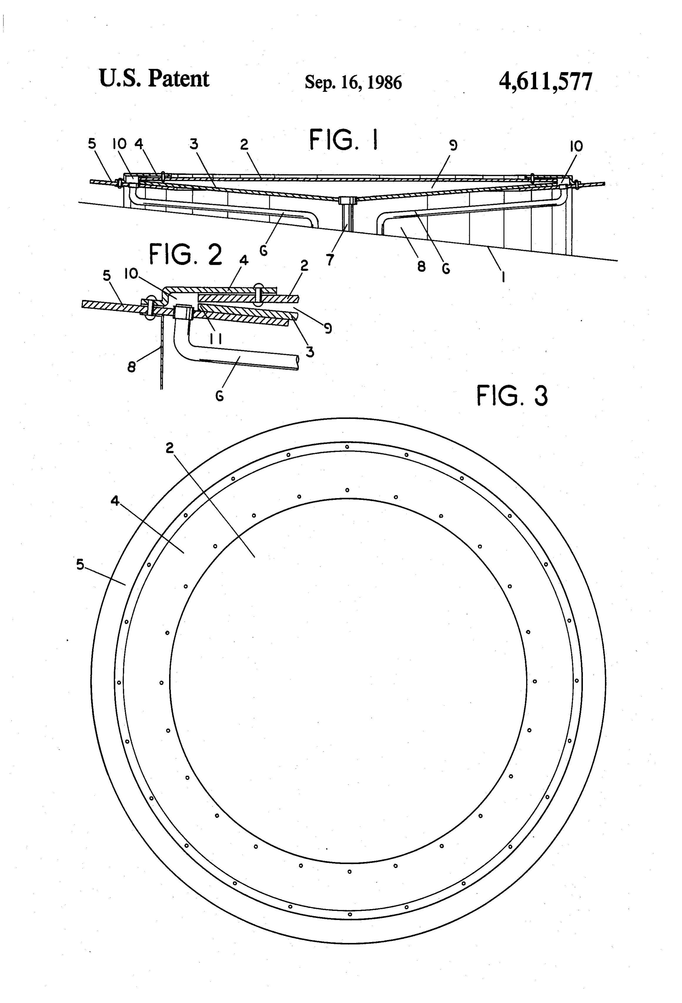
solar radiation into the water. Secondary sources are by FIG. 3 shows the relative dimensions of the parts conduction through the plate glass window and by exposed to the sun.
conduction through the metal disk which receives heat 30 I claim:
from an exposed flange. 1. A black-water solar collector comprising, a flat The use of the forces of thermal expansion to circu disk circular plate glass window (2), a conical circular metal late the water eliminates the need of pumping the water. edges,(3)anhaving a center aperature and vertical outer annular metal plate (4), a flange plate (5), inlet
DRAWINGS tubes (6), an outlet tube (7) and a housing (8); the afore 35 mentioned parts in combination forming;
FIG. 1 is an elevation of the black-water solar disk a. an expansion chamber (9) formed by said flat glass mounted on a sloping roof. window (2) mounted above said conical disk (3), FIG. 2 is an enlarged view of the outer portion of the the conical surfaces of said disk inclined 5' from disk. the horizontal, with the interior vertical dimen FIG. 3 is a top view of the disk. 40 sions of chamber (9) being 1 mm at the outside edge DESCRIPTION and 15 mm at the center, b. a peripheral gap (11) of 1 mm formed by plate (4),
FIG. 1 is an elevation of the black-water solar disk flange plate (5) and the vertical outer edges of mounted on a sloping roof indicated by roofline 1. The window (2) and disk (3), disk consists of flat circular plate glass window 2, coni 45 c. an inlet means formed by the communication of cal circular metal disk 3, annular metal plate 4, flange said inlet tubes (6) with an annular inlet manifold plate 5, inlet tubes 6, outlet tube 7 and housing 8. (10) and the communication of said inlet manifold Expansion chamber 9 is formed by window 2 and disk (10) with peripheral gap (11), 3. d. an outlet means formed by the communication of Annular inlet manifold 10 is formed by plate 4, flange 50 the center aperature of said conical disk with the outlet tube (7), and plate 5 and the vertical edges of window 2 and disk 3. e. water to which a black dye has been added to FIG. 2 is an enlarged view of the outer portion of the render the water opaque to the transmission of black-water solar disk showing peripheral gap 11 of 1 light.
mm between the edges of window 2 and disk 3. 55 sk k k sk. k.
Provenance
- Collection
- Patents citing this work
- Pages
- 3
- Method
- pdftotext (the PDF's own text layer) + pdftoppm 300dpi page scans
- Patent office record
- patents.google.com →
- Source
- Google Patents citing-documents table
- Assignee
- Clegg John E
- Published
- 1986-09-16
- Transcribed from
- patentimages.storage.googleapis.com →