

patent · US4612726A
Plant cultivating device
23 September 1986
Text
Page 1bibliographic recordscan →
United States Patent (19)
Mori
PLANT CULTIVATING DEVICE
76 Inventor: Kei Mori, 3-16-3-501, Kaminoge,
Setagaya-ku, Tokyo, Japan
30 Foreign Application Priority Data
Jan. 27, 1984 (JP) Japan .................................. 59-1413 Int. Cl. ............................................... A01G 9/02 52 U.S.C. ............................................ 47/66; 47/17
1,504,721 8/1924 Sauvé et al. ..... ... 47/17 2,354,665 8/1944 Church et al. ... ... 362/35 2,599,162 6/1952 Brown .......... 220/336 3,324,593 6/1967 Strasser .... ... 47/65 3,348,922 10/1967 Bose et al. .... ... 47/17 3,453,786 7/1969 Rebarchek ... ... 47/17 3,780,722 12/1973 Swet .................................... 126/451
4,201,197 6/1980 Dismer ................................ 126/45 4,441,145 4/1984 Antkowiak .......................... 362/122
FOREIGN PATENT DOCUMENTS
Primary Examiner-Robert A. Hafer
Assistant Examiner-Bradley M. Lewis
Attorney, Agent, or Firm-Jordan and Hamburg
A plant cultivating device enables plant cultivation by effective use of the floor's dimension at a place of high cost per unit dimension of the floor on the building erected in the urban district.
The plant cultivating device comprises a cylinder and an upper plate for covering the upper portion of said cylinder. The cylinder being constructed by combining two side plates, the side surface of which is unitarily formed. The upper plate being constructed with trans parent material.
11 Claims, 10 Drawing Figures
Drawings
Page 2drawing sheetscan →
Page 3drawing sheetscan →
Page 4drawing sheetscan →
Page 5drawing sheetscan →
Page 6drawing sheetscan →
Page 7drawing sheetscan →
Page 8scan →
ide. By employing such a construction, the plant culti
PLANT CULTIVATING DEVICE vating tub can be supplied with air containing carbon dioxide.
BACKGROUND OF THE INVENTION Furthermore, in order to cultivate plants more effec The present invention relates to a plant cultivating 5 tively, they need to be provided with a period of bright device, in particular, a plant cultivating device which ness and a period of darkness corresponding to daytime enables plant cultivation by efficient use of floor space and night time. Those periods have to be in an order of in an expensive building erected in an urban district. hours. The brightness period represents the time period A proper amount of nutrients and proper atmospheric 10 for performing a photosynthesis while the darkness conditions such as carbon-dioxide (co2), water, temper period represents the time period for performing a de ature and humidity, etc. are needed in order to effec livery or transportation of nutritious substances from tively nurture plants. However, it is often difficult to the leaves, to the fruits, and to the trunk. During the obtain all of these at one time. The ground needs to be brightness period, carbon-dioxide is needed for per prepared for nurturing plants. However, it is not easy to forming the photosynthesis. On the contrary, oxygen is acquire space or ground for cultivating plants in urban 15 needed for breathing during the darkness period. There districts. fore, it may be preferable to supply carbon-dioxide of a In order to solve such a problem, the present appli comparatively high and adequate temperature and an cant previously proposed a method or an apparatus in adequate humidity during the brightness period and to which solar rays were focused by a lense or the like and supply oxygen of a comparatively low temperature guided into an optical conductor and then further 20 during the darkness period.
guided through the optical conductor onto a plant culti vating device which was installed in an optional desired SUMMARY OF THE INVENTION place for receiving light energy for plants. Furthermore The primary object of the present invention is to the present applicant has proposed a plant cultivating provide a plant cultivating device which can be simply device in which artificial light rays were employed in manufactured and assembled and which is of a low-cost addition to solar rays. (Refer to Japanese Patent Appli and also durable.
cation No. 58-119866.) Another object of the present invention is to provide The plant performs a photosynthesis through the use a plant of light energy given it and delivers or transmits nutri forming cultivating its task.
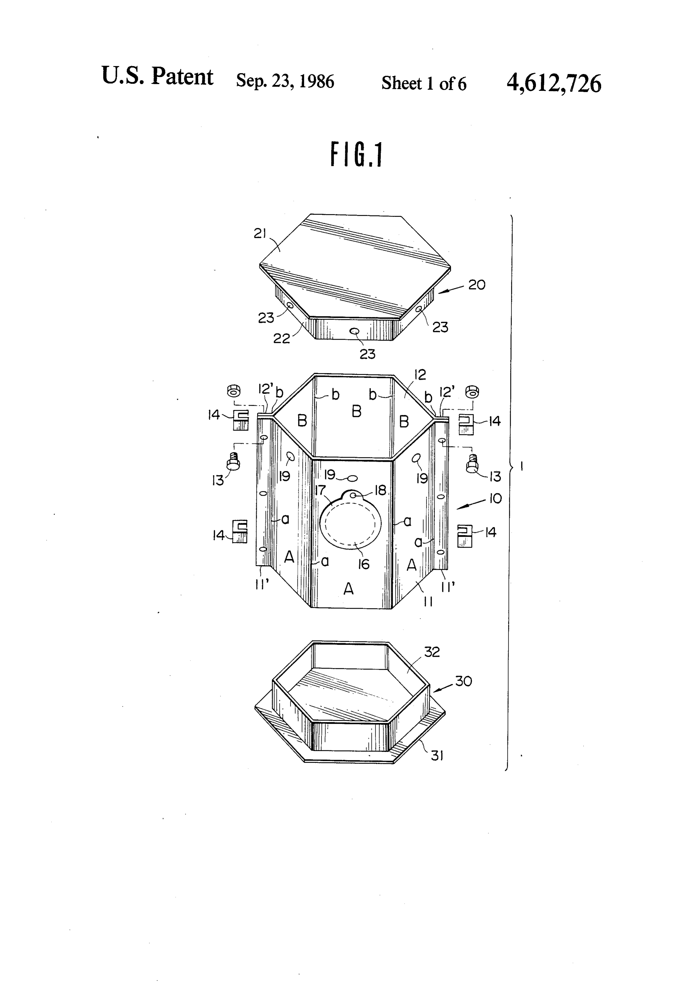
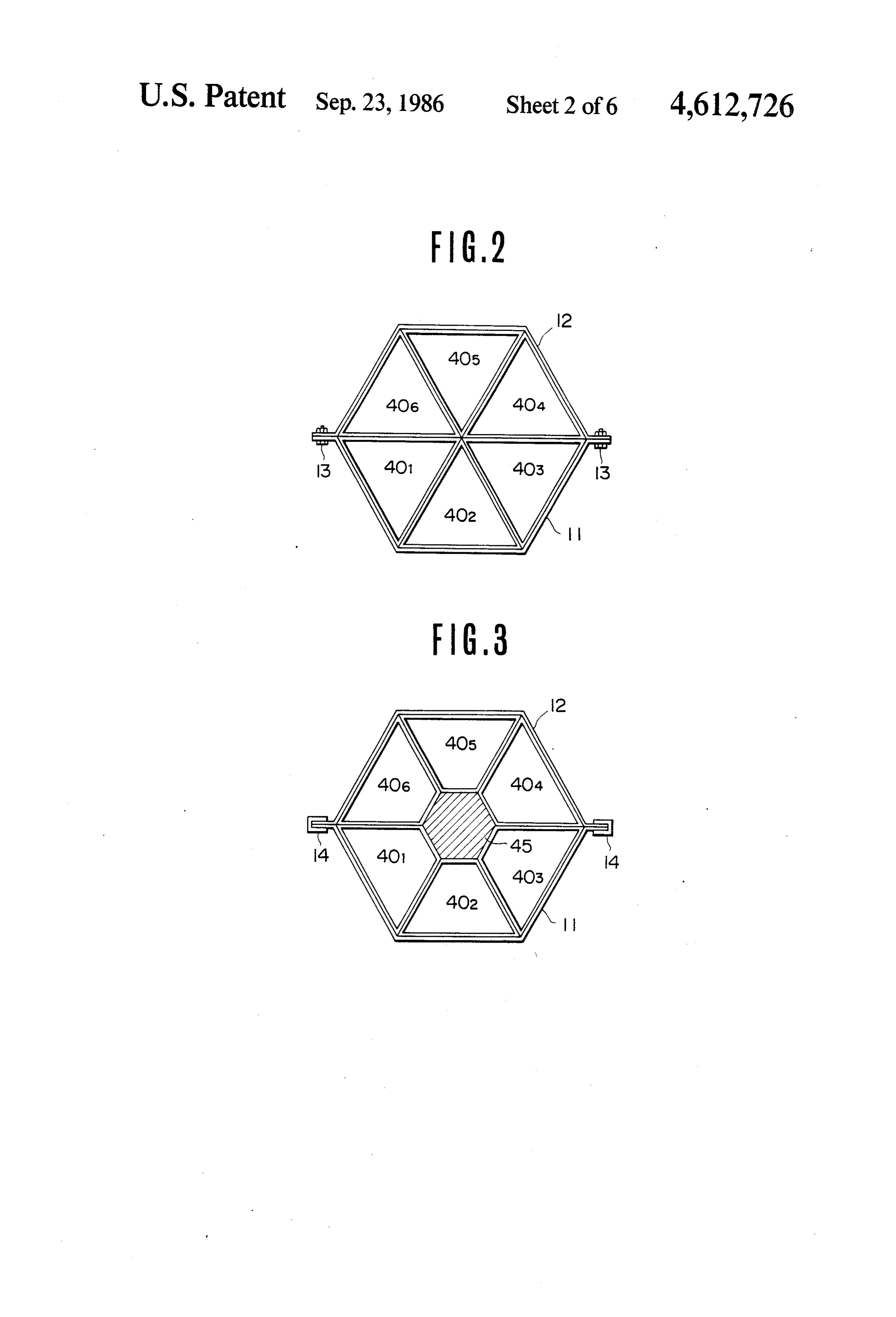
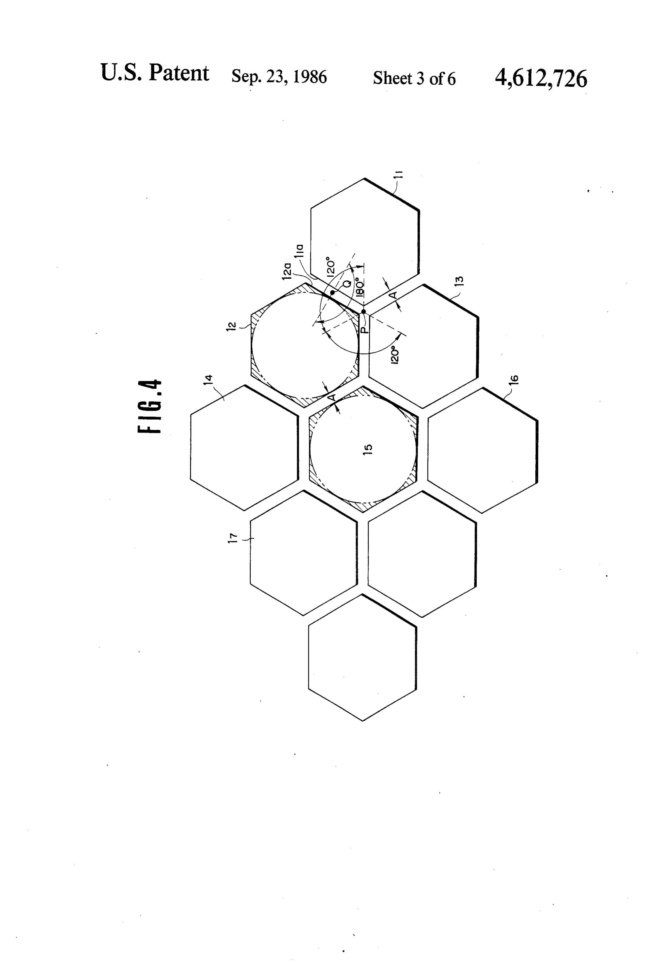
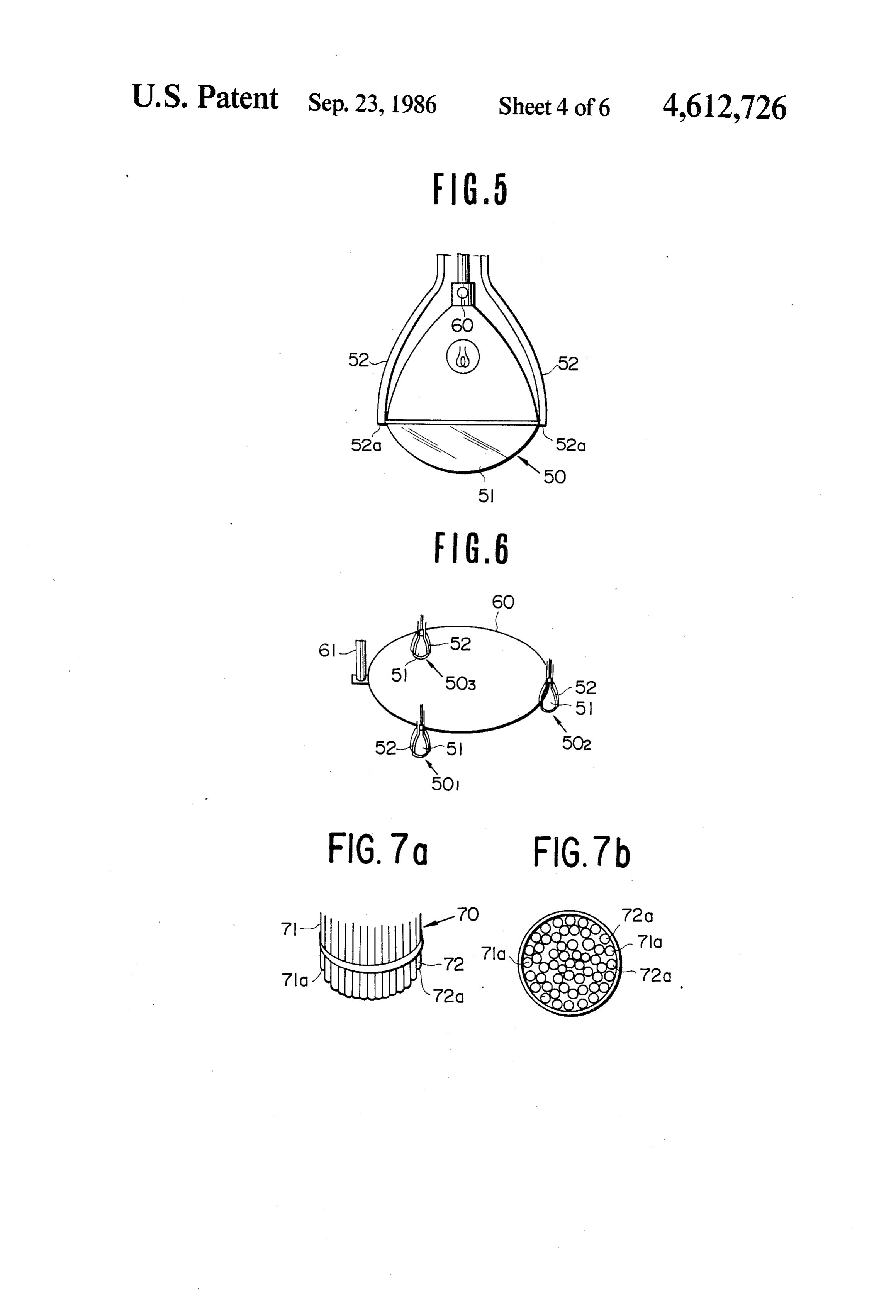
device capable of effectively per tious substances produced by the action of the photo 30 Still another object of the present invention is to synthesis to its trunk, fruits, etc. Such delivery of trans provide a plant cultivating device capable of cultivating portation can be more effectively carried out when plants within a narrow space. there is no light; there is sufficient oxygen; and there is a low ambient temperature. Therefore, in order to nur BRIEF DESCRIPTION OF THE DRAWINGS ture plants, more effectively, it is necessary to cause 35 photosynthesis to occur and then nutrious substances FIG. 1 is an analytical view for explaining an embodi are transmitted to the limbs, trunk, and fruit of the plant. ment of a plant cultivating device according to the In order to effectively cause photosynthesis to occur present invention;
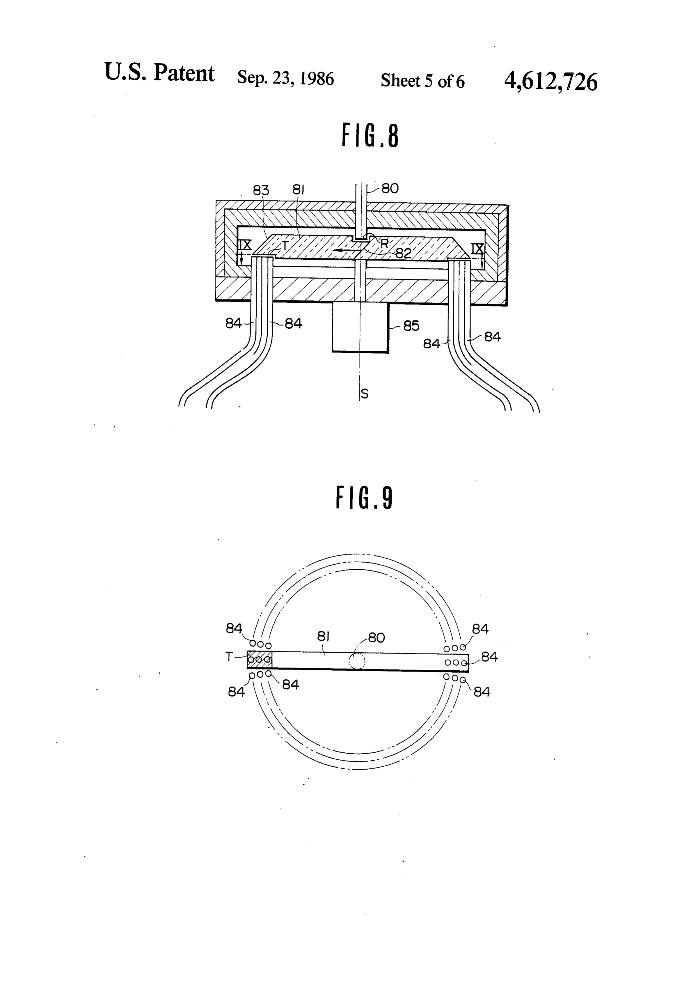
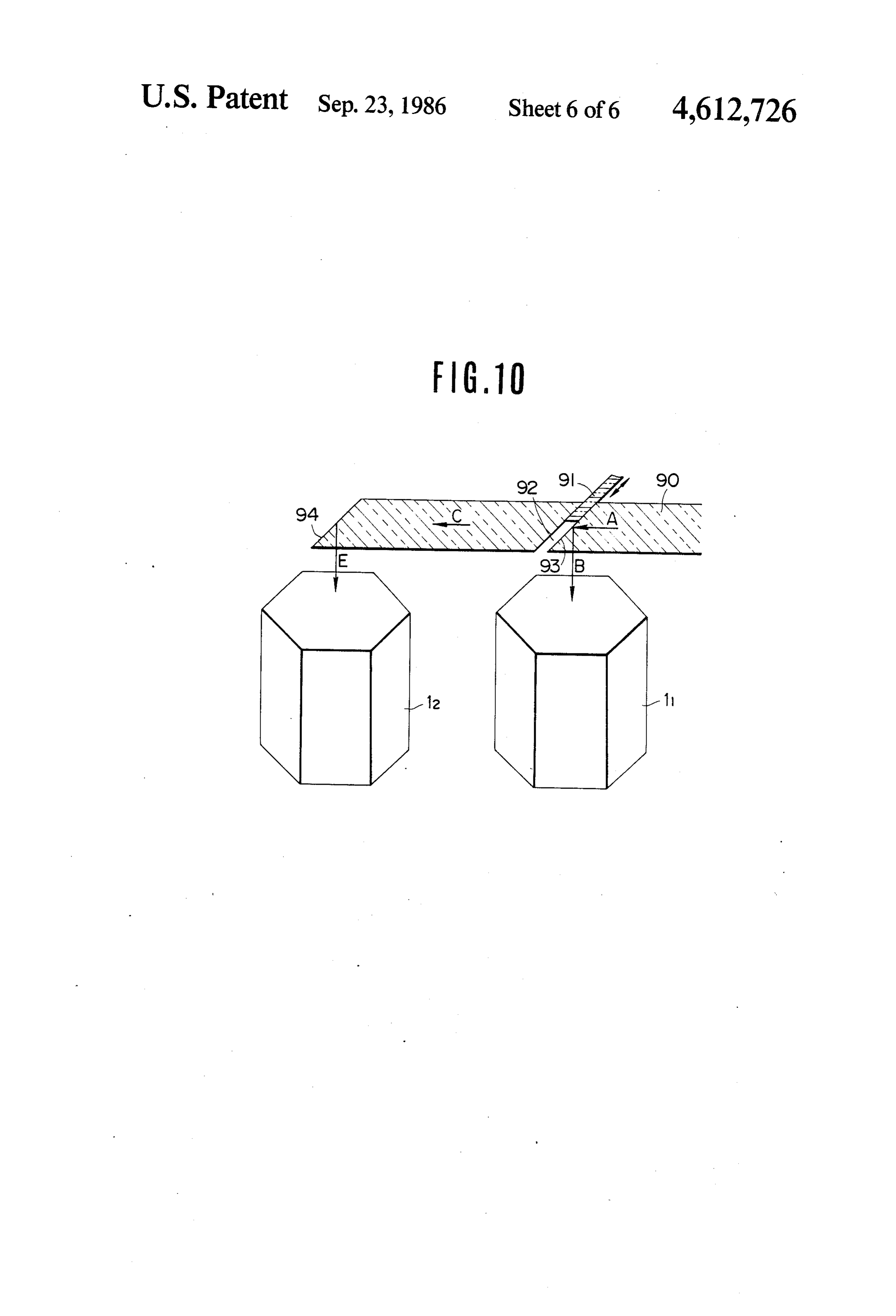
and for the subsequent transmission of nutrients to the FIGS. 2 and 3 are plane views showing embodiments limbs, trunk and fruits of plant to take place, periods of 40 of the plant cultivating floor container preferably em brightness and darkness must be alternated at predeter ployed for embodying the present invention; mined intervals. FIG. 4 is a plane view showing the floor containers Furthermore, in the case of nurturing plants, it may according to the present invention in the case of arrang be preferable to supply light rays to the plant intermit ing a large number of plant cultivating tubs; tently (several us to several ms) instead of continuously. 45 FIGS. 5 through 7 are views showing embodiments Specifically, the photosynthesis consists of a brightness of the light source device, respectively; reaction and a darkness reaction, and intensified light FIGS. 8 and 9 are views for explaining an emobid rays are given to the plant during the time period of a ment of the light switching mechanism; and brightness reaction while no light rays or rather weak FIG. 10 is a perspective view showing an embodi ened light rays are given during the time period of a 50 ment of the light switching mechanism. darkness reaction. In such a manner, the growth of the DESCRIPTION OF THE PREFERRED plant is enhanced. EMBODIMENTS When using a movable light source device, the utili zation area of light energy can be increased compared FIG. 1 is a breakdown view for showing an embodi with the use of a fixed light source. Namely, in the case 55 ment of a plant cultivating device according to the of employing a light source of the same capacity, the present invention. In FIG. 1, 1 is a plant cultivating plant can be cultivated over a wider area. In addition to device according to the present invention. Basically the that, the shadowed portion created by the leaves of the plant cultivating device container or tub 1 is air-tightly plant changes every moment in accordance with the constructed by combining a hexagonal cylinder 10, an afore-mentioned movement of the light source device, 60 upper cover 20 and a plant cultivating floor 30. The so that the brightness reaction and the darkness reaction plants to be cultivated are arranged within the inner are effectively alternated. In such a manner, growth of portion of the plant cultivating device. the plant can be much more effectively promoted. In the present invention, the hexagonal cylinder 10 is Furthermore, in order to nurture the plant effec constructed by combining the flanges 11" and 12" of two tively, it is necessary to give it a proper amount of nutri 65 side plates 11 and 12 consisting of a side plate having tious substances, light rays, water, carbon-dioxide, tem unitarily three-sided surfaces A and another side plate perature, and humidity. The plant cultivating tub has to having, unitarily, three-sided surfaces B respectively by be hermetically-sealed in order to supply carbon-diox means of bolts 13 or fixed members 14 in the shape of 9 shown in FIG. 1. In such a manner, the manufacturing der has been described thus for, but the present inven and assembling of the hexagonal cylinder are very easy. tion is not limited to that embodiment. For example, In addition, the cost can be greatly reduced and it can square cylinders, triangular cylinders, and round cylin be made in a strong and durable way. Namely, the side ders can be used also.
plates 11 and 12 are preferably constructed with artific The upper cover 20 consists of a transparent upper ial resin such as plastic or the like. Those plates 11 and cover 21 and a hexagonal cylinder 22 which are unitar 12 can be easily formed with press-processing operation ily attached to the lower side of the upper cover 21. including, heating the bent portions a and b of the When the side plates 11 and 12 are unitarily combined plates. It is preferable to construct those plates 11 and by use of bolts or the like as mentioned above, the outer 12 using transparent plastic. A part of the plates is O circumferential surface of the hexagonal cylinder 22 formed as a reflection surface. For instance, as shown in
FIG. 1, leaving out only the portion 16 of the side plate and 11 the inner circumferential surface of the side plates and 12 are tightly brought into contact with each 11, the inner surface or the outer surface of the side other so as to make it air-tight between them. On that plate 11 is formed as a reflecting surface by performing occasion, if a packing or the like is inserted between the evaporation treatment with a metal such as aluminium. 5 hexagonal cylinder 22 and the side plates 11 and 12, As is described hereinafter, the light rays guided into the hexagonal cylinder are reflected on the reflecting more The reliable air-tightness can be obtained.
upper cover plate 21 is constructed with a trans surface and are effectively supplied to the plants which parent substance, are accommodated in the hexagonal cylinder for the mentioned above,according for the to the present invention, as purpose of guiding the light purpose of effectively promoting the photosynthesis of 20 rays from the upper side of the transparent plate 11 into the plants. the hexagonal plant cultivating tub 10 through the Furthermore, the above-mentioned portion 16 is transparent plate 11. The method of guiding the light notched in order to form a window hole. The extent of the plant growth in the hexagonal cylinder can be ob rays is described below.
served through the window hole portion 16. Otherwise, FIG. shown 25 As in the perspective view of a side plate 11 in 1, at least one side surface of the hexagonal cylin fruits, or the like, to be harvested can be taken out through the window hole portion 16. der 22 of the upper cover portion 20 has a hole 23 bored As mentioned before, the plants can be much more upper therein, which corresponds to a hole 19 bored in the effectively nurtured by alternating brightness periods portion of the side plate 11. The upper cover and darkness periods at certain time intervals. How 30 portion 20 is fixedly mounted on the hexagonal cylinder ever, the light rays guided into the hexagonal cylinder 10 by means of the bolts passing through those holes. leak outside through the window hole portion 16 and When the side plate 12 is removed at the time of taking therefore the utilization efficiency thereof decreases care of the plants accommodated in the cylinder, the during the brightness period while the external light upper cover portion 20 is fixed on the upper portion of rays are guided into the hexagonal cylinder from out 35 the side plate 11.
side through the window hole portion 16 during the The plant cultivating floor 30 consists of a bottom darkness period so that the cultivation of nurtured plate 31 and a hexagonal cylinder 32 which are unitarily plants is obstructed. In order to avoid such problems, a mounted on the upper portion of the bottom plate 31. cover plate 17 is set up at the external side of the win As is the case of the afore-mentioned upper cover por dow hole portion 16, and it can be opened and shut 40 tion, when the side plates 11 and 12 are combined into freely. The internal surface of the cover plate 17 is one by means of the bolts 13 or fixed members, the outer formed as a reflecting surface and the cover 17 can be circumferential surface of the hexagonal cylinder 32 freely rotated around a pin 18. By use of such a design, tightly comes into contact with the inner circumferen opening and closing the window hole portion 16 can be tial surfaces of the side plates 11 and 12 in order to make easily done. 45 it air-tight between them. As a result, the air-tightness An example of converting the transparent side plates between them can be made much more reliable by in 11 and 12 into reflecting surfaces by performing metal serting packing between the hexagonal cylinder 32 and evaporation on the internal or external sides of them has the side plates 11 and 12.
already been described. Instead, a cover plate having an Under such circumstances it may be possible to raise internal side formed as a reflecting surface can be re 50 the plants directly in the hexagonal cylinder 32 of the movably mounted on the external side of the hexagonal plant cultivating floor 30. Otherwise, it may be also cylinder without performing reflection-film processing possible to put one or more plant cultivating floor con as mentioned above on the transparent side plate. In tainers in the hexagonal cylinder 32. In such a manner, such a manner, by removing the cover plate, the plants the plants to be cultivated can be freely taken in or in the hexagonal cylinder can be observed. On that 55 taken out or exchanged for others.
occasion, if the cover plate is removably mounted on Furthermore, instead of the plant cultivating floor 30 the respective side surfaces, the plants in the hexagonal as mentioned above, six triangular plant cultivating cylinder can be observed from an optional desired floor containers (401 - 406) are prepared as shown in place. FIG. 2. Those containers can be arranged by combining The construction of the side plates 11 and 12 for 60 them in the shape of a hexagon and two side plates 11 making the hexagonal cylinder 10 with a transparent and 12 can cover the external side of the hexagonal substance has been described heretofore. However, it is body. In such a manner, when each plant cultivating not always necessary to construct the side plates 11 and floor container is taken in or taken out, it may be possi 12 with a transparent substance. Those plates can be ble to put in or take out the container by moving it in a constructed with an opaque substance. In the case of 65 horizontal direction. Therefore, the plant cultivating constructing the side plates 11 and 12 with an opaque floor container can be put in or taken out without any substance, the inner surface of the side plate is formed as mutual interference between the neighboring plant cul a reflecting surface. Only the case of a hexagonal cylin tivating floor containers.
Page 10scan →
However in such a case six plant cultivating floor tubs is A at the nearest position, and larger than A in the containers are always needed. For instance, when one other area. Namely, excessive space as shown in the of the plant cultivating floor containers is taken out, the hatched area of FIG. 4 increases and therefore the effi other plant cultivating floor container is put in its place. cient utilization of floor space is lessened. Namely, six containers always need to be used. In such As mentioned above, the plant cultivating tub ac a construction, air-tightness can be maintained at the cording to the present invention has a window hole lower portion of the plant cultivating tub. portion 16 for observing the growth condition of the In the embodiment shown in FIG. 2, if the packing or plants accommodated in the plant cultivating tub, or for the like which is put in between the respective contain taking care of the plants, or for harvesting the fruits ers or between the respective containers and the side 10 therefrom. The light rays enter the plant cultivating tub plates, air-tightness therebetween can be maintained through the window hole 16 or leak outside from the more reliably. However, airtightness inside the plant tub therethrough. There is a fear that the light rays cultivating tub is not consistent. As the case may be, if leaking through the window hole portion of one plant air-tightness is sufficient to keep the humidity constant cultivating tub is guided into the other neighboring inside the plant cultivating tub, it may be acceptable. 15 plant cultivating tub through the window hole thereof. Otherwise, if one of the end portions of the triangular For this reason, it is necessary to arrange the respective floor containers is cut off as shown in FIG. 3 and six neighboring plant cultivating tubs in such a manner that triangular floor containers are arranged so as to have the window hole portions are not opposite to each the cut-off portions at the center, a space in the shape of other.
a hexagon is created there, A hexagonal cylinder 45 is 20 For example, in the neighboring two plant cultivating arranged in the space and a packing or the like is put tubs 11 and 12, the tub 11 has a window hole portion at between the cut-off portion of each floor container and its side surface 11a and the tub 12 has a window hole the hexagonal cylinder 45 for the purpose of keeping portion at its side surface 12a opposed to the side surface them air-tight. 11a of the tub 11. If the plant cultivating tub 11 is in the Furthermore, it may be possible also to elongate the 25 brightness period and the plant cultivating tub 12 is in hexagonal cylinder 45 to the upper cover 20 and to the darkness period, when the window hole portions of support the upper cover 20 by the upper edge portion of both plant cultivating tubs are opened the light rays the hexagonal cylinder 45. Furthermore it may be possi leaking through the window hole portion of tub 11 are ble also to set up a supporting pole for supporting the guided into tub 12 through the window hole portion of trunk or the branches that are on the hexagonal cylinder 30 tub 12 and the plants accommodated in tub 12 in the 45. Otherwise, it may be possible that one of the tip end darkness period are supplied with light rays, and as a portions of the triangular floor containers is cut off in result the growth of the plants in tub 12 is hindered. In the shape of a circular arc and a circular cylinder is order to avoid such an obstacle, the window hole por employed instead of a hexagonal cylinder 45. tion of tub 11 or 12 is provided at the side surface except An embodiment of the plant cultivating tub accord 35 for the afore-mentioned side surface. Namely, it is ar ing to the present invention has been described hereto ranged so as to avoid being opposite to each other. fore. The plant cultivating tub explained here can be FIG. 5 is a side view for explaining an embodiment of effectively used even though a single plant cultivating the light source device supplying light energy for caus tub is used in the device. However, especially in the ing photosynthesis to the plants accommodated in the case of a square cylinder or a hexagonal cylinder, a 40 plant cultivating tub as mentioned above. In FIG. 5, the large number of plant cultivating tubs can be arranged light source device 50 consists of a light source (an in a narrower space and can be much more effectively electric bulb) 51 for generating an artifical light and an used. optical conductor 52 to which the solar rays collected FIG. 4 is a plane view showing the floor containers by the solar ray collecting device, not shown in the according to the present invention as in the case of 45 drawings, are transmitted therefrom. The edge portion arranging a large number of plant cultivating tubs in the (not shown in the drawings) of the optical conductor 52 shape of a hexagonal cylinder. In FIG. 4, 11, 12, 13, . . . is positioned at the focal point of the lense for focusing are the plant cultivating tubs corresponding to the plant the solar rays, and the solar rays focused by the lense cultivating tub 1 shown in FIG. 1. Those plant cultivat are guided into the optical conductor 52 and propagated ing tubs are constructed in the shape of a hexagon, a 50 through the optical conductor 52 and finally are emitted square, or a cylinder. Therefore, if the respective tubs from the edge portion 52a, as previously proposed in are arranged so as to let each side be opposite to the various ways by the present applicant. other as shown in FIG. 4, useless space can be reduced In the case of nurturing plants, growth of the plants is to a minimum and the plant cultivating tubs can be most promoted better by intermittently supplying the light effectively arranged. Especially, the plant cultivating 55 rays to the plants than in continuously supplying the device is effective in the case of employing it in an light rays thereto, as mentioned heretofore. When the urban district where the cost of floor space is high. light source device is moved, the area shadowed by the Furthermore, in order to observe growth conditions preceding leaves changes every moment in accordance of the plants accommodated in the respective plant with the movement of the light source device. In conse cultivating tubs, it is necessary to provide passages be 60 quence, the brightness reaction and the darkness reac tween the plant cultivating tubs. In such cases the pas tion are effectively repeated.
sage width. A needs to be the width of a person. Accord Further, as mentioned above, the controlled repeti ing to the present invention, the passage width A is tion of brightness periods and darkness periods enables nearly constant and needs only a minimum of space. For the promotion of plant growth. For this reason, a single instance, in the case of constructing the plant cultivat 65 light source can be employed by changing it from one ing tub in the shape of a circular cylinder, each plant plant cultivating tub to an other. cultivating tub is the one as shown by a two-dots-and-a- Consequently, in the case of changing the single light dash line. The distance between the neighboring two source device from one plant cultivating tub 11 to the 11 other plant cultivating tub 12, the light source device is FIG. 7(a) and 7(b) are views showing the case of moved onto the plant cultivating tub 11 and supplies the constructing a light source device only by the means of light rays to the plants accommodated in the plant culti the light-emitting edge of the optical conductor. FIG. vating tub 11 during a predetermined time period. On 7(a) is a side view of the light source device and FIG. the other hand, the light rays are not supplied to the 7(b) is an edge-surface view thereof. In FIG. 7, 70 is a plants accommodated in the plant cultivating tub 12 light source device, 71 is an optical conductor to which during that same period. After the predetermined time the solar rays are transmitted, and 72 is an optical con period has elapsed, the light source device is moved ductor to which the artificial light rays are transmitted. onto the plant cultivating tub 12 and supplied the light The light source device 70 is constructed by combining rays to the plants accommodated in the plant cultivating O optical conductors 71 and 72. As is well known, each tub 12. The performance as mentioned above is intermit edge portion not shown in the drawings of the optical tently repeated thereafter. On that occasion, if the light conductor 71 is arranged at the focal position of the source device effectively creates a brightness reaction lense for focusing the solar rays, and the solar rays and a darkness reaction to the plants in the plant culti 15 focused by the lense are guided into the optical conduc vating tubs 11 and 12, growth of the plant is effectively tor 71. Each edge portion not shown in the drawings of promoted. Solar rays are preferable for nurturing the optical conductor 72 is arranged at the focal posi plants. However, since solar rays cannot be utilized at tion of the lense for focusing the artifical light rays night or on cloudy days, a combination of solar rays generated from the artificial light source lamp, and the with artifical light rays is needed to effectively promote artificial light rays focused by the lense are guided into the growth of the plants. In respect to that matter, the 20 the rays optical conductor 72. In such a manner, the solar and the artificial light rays, guided into the respec present applicant has already proposed the same kind of device in various ways. tive optical conductors 71 and 72 and propagated there FIG. 6 is a perspective view showing an embodiment through respectively, finally are emitted from the edge of the light source device preferably employed in the 25 portions 71a and 72a respectively. In FIG. 7, the case of emitting the solar rays and the case of arranging a large number of plant cultivating artificial light rays from different optical conductors has tubs as mentioned above. The light source device has a been described.
plurality of light source portions 501, 502, 503. (Those solar rays and theHowever,artificial it may be possible that the light rays guided into the are the same in construction as the light source device optical conductors respectively, as mentioned above, 50 shown in FIG. 5.) Those light source portions are 30 mounted on a single arm 60 and the respective light are guided into a single optical conductor. The guided light rays propagate through the optical conductor and source portions 501-503 are arranged, for instance, on are emitted from the edge portion of the single optical a single plant cultivating tub. For example, those light conductor.
source portions can move or be moved around the shaft structing theInlight such a manner, even in the case of con source device only by means of the 61. 35 Eight-emitting edge of the optical conductor, the light Furthermore, the arm 60 is mounted on the shaft 61 source device can be moved, vibrate or be vibrated just so as to rotate around it. When the shaft 61 is set up at like in the embodiment explained in connection with point P shown in FIG. 4, the light source device can be FIG. 5 and FIG. 6 mentioned above. And further, if the alternately employed on the plant cultivating tubs 1, 12 optical conductor is employed, the exchange and and I3 by rotating the shaft 61 in the angle area of 240. 40 switching of the light rays can be easily performed so When the shaft 61 is set up at point Q shown in FIG. 4, that the utilization efficiency of the light rays can be the light source device can be alternately employed on greatly improved as will be explained hereinafter. the plant cultivating tubs I and I2 by rotating the shaft FIGS. 8 and 9 are views for explaining an example 61 by 180°. For instance, after supplying the light rays case of utilizing the light rays propagating through the to the plants in the plant cultivating tub 11 for a prede 45 optical conductor as mentioned above. The present termined time period, the shaft 61 is rotated by 120 or applicant has already proposed it. (Refer to Japanese 180°. At this time, the plant cultivating tub 11 supplied Patent Application No. 57-17238.) According to the with light rays until then is no longer supplied with above-mentioned embodiment, the switching of the them. Instead, the light rays are supplied to the plant light rays can be easily performed so that the brightness cultivating tub 12 newly arranged under the light source 50 reaction and the darkness reaction can be effectively portions 501-503. In the case of setting up the shaft 61 promoted. Namely, in FIGS. 8 and 9, 80 is an optical at point P the light source device is alternately em conductor to which the solar rays and/or the artifical ployed on the plant cultivating tubs I1, I2 and I3 repeat light rays, and 81 is a transparent rotating rod. The edly for a predetermined time period, while in the case light-emitting edge R of the optical conductor 80 is of setting up the shaft 61 on point Q it is also alternately 55 provided so as to be opposite to the rotational center S employed on plant cultivating tubs I and I2. of the rotating rod 81.
The case of commonly employing a plurality of plant Furthermore, a reflecting mirror 82 is provided at the cultivating devices by rotating the light source device rotational center S of the rotating rod 81, opposite to has been described heretofore. However, it may be the light-emitting edge R of the optical conductor 80. easily understood that the light source device can be 60 The light rays guided into the rotating rod 81 from the rotated so as to travel on a plurality of plant cultivating optical conductor 80 are reflected on the reflecting tubs 11, 12, 13, . . . , I6, . . . , in that order. mirror 82 and propagate toward the (circumferential) The case of constructing the light source device by end portion of the rotating rod 81. The light rays are means of the artificial light source lamp and the light further reflected on a reflecting mirror 83 provided at emitting edge portion of the optical conductor have 65 the (circumferential) end portion and emitted outside also been described heretofore. It may also be possible from the rotating rod 81 through a light-emitting sur to construct a light source device only by means of the face T. A large number of optical conductors arranged light-emitting edge of the optical conductor. opposite to the light-emitting surface T of the rotating 12 rod 81 are represented by 84. The light-receiving edge with the brightness period or the darkness period, the surfaces of a large number of optical conductors are utilization efficiency of carbon-dioxide can be im arranged in a circular state so as to be opposite to the proved. Therefore, the piping system is preferably con light-emitting surface T of the rotating rod 81 as shown structed so as to transfer carbon-dioxide in synchronism in FIG. 9. with the movement of the light source device or the Consequently, when a motor 85 rotates, the rotating exchange thereof.
rod 81, the light-receiving surface of the optical con Various embodiments of the present invention have ductor 84 opposite to the light-emitting surface T of the been described heretofore. However, the present inven rotating rod 81 is exchanged for the other in order and tion is not limited to the embodiments as mentioned in accordance with the rotation of the rotating rod 81. O above. For instance, in relation to the afore-mentioned The light rays are instantaneously supplied once to each light source device, it may be easily understood that optical conductor 84 at every rotation of the rotation various combinations of the solar rays with artificial rod 81 so that the right rays from the optical conductor light rays are possible except for the combination men rod 84 are switched. In consequence, if the other edge tioned above.
portions each optical conductor 84 are guided into the 15 As is apparent from the foregoing description, ac plant cultivating tub as mentioned before, the light rays cording to the present invention, it may be possible to are supplied to the plants in the plant cultivating tub, provide a plant cultivating tub which can be simply and the photosynthesis, namely, the brightness reaction manufactured and assembled and is low-cost and dura and the darkness reaction can be effectively performed. ble. Further, it may be possible to provide a plant culti FIG. 10 is an outlined, perspective view showing an 20 vating tub capable of effectively nurturing plants by embodiment of the light switch for switching on and effectively using a limited amount of floor space. switching off the light rays propagating through the What is claimed is:
optical conductor. The present applicant has already 1. Plant cultivating apparatus comprising a plurality proposed the light switch as mentioned above. By em of pairs of upright side plates each made of a transparent ploying such a light switch, as an example, it may be 25 material, joining means for joining each of said pairs of possible to effectively switch the light rays propagating side plates to form a plurality of upright hexagonal through the optical conductor in such a manner as men containers, a transparent upper cover mounted on the tioned before. Therefore, the light rays propagating top of each of said containers to provide an air-tight seal through the optical conductor can be alternately sup between said cover and the respective container, said plied to either one of two plant cultivating tubs and it 30 upper covers being made of a transparent material, a may be possible to easily give the brightness period and bottom member means mounted on the bottom of each the darkness period thereto. of said containers to provide an airtight seal between In FIG. 10, 90 is an optical conductor and 91 is a said bottom member means and the respective contain transparent plate which can be inserted and removed in ers, each of said hexagonal containers having six side a direction crossing the optical conductor 90. The solar 35 walls, said plurality of containers being disposed in rays are transmitted into the optical conductor 90. Sup spaced array such that a first side wall of a first hexago posing that the transparent plate 91 is not inserted into nal container is disposed in spaced parallel alignment the optical conductor 90, the light rays propagating with a first side wall of a second hexagonal container, a through the optical conductor 90, in a direction shown second side wall of said first hexagonal container is by an arrow A, are reflected on the edge surface 93 of 40 disposed in spaced parallel alignment with a first side the optical conductor 90 neighboring the insertion wall of a third hexagonal container, and a second side removal space portion 92 for inserting and removing wall of said second hexagonal container is disposed in the transparent 91 and directed to direction B. When spaced parallel alignment with a second side wall of said the transparent plate 91 is inserted into the optical con third hexagonal container to thereby form a space be ductor 90, the light rays propagate in direction C 45 tween said first, second and third hexagonal containers through the transparent plate 91 and are reflected on the having a generally Y-shaped configuration having three edge portion 94 of the optical conductor 90 and further leg portions joined at a common center with the angle directed to direction E. between each leg portion being 120 degrees, a light Consequently, for instance, the light rays from the source means disposed above said hexagonal containers, insertion-removal space portion 92 are supplied to the 50 said light source means comprising a rotatable shaft, an plant cultivating tub 11 and the light rays from the edge arm mounted on said rotatable shaft, and at least one portion 94 are supplied to the plant cultivating tub 12. In light device mounted on said arm for directing light such a manner, the light rays propagating through the onto said hexagonal containers, said rotatable shaft optical conductor 90 can be alternately supplied to plant being disposed upright for rotation about an axis coindi cultivating tubs 11 and 12 by removing or inserting the 55 cent with said common center of said Y-shaped space transparent plate 91. If such an operation is performed such that said shaft can be rotated to dispose said arm at intervals of a predetermined time period, it may be and said light device in a plurality of rotatable positions possible to give effectively the brightness period and to direct light from said light device onto either one of the darkness period to the plants in the plant cultivating said first, second and third hexagonal containers, tubs 11 and 12, respectively. 60 whereby said first, second and third hexagonal contain Moreover, supposing that carbon-dioxide of a com ers can be selectively exposed to said light from said paratively high and adequate temperature and adequate light device depending on the rotational position of said humidity is supplied to the plants during the brightness shaft to thereby provide for controlled repetition of period and oxygen (air) of comparatively low tempera lighted and non-lighted periods in said containers to ture is supplied thereto during the darkness period, 65 thereby enhance the promotion of plant growth in said growth of the plant can be further promoted as men containers.
tioned before. If carbon-dioxide is exchanged for the 2. Plant cultivating apparatus according to claim 1, other between two plant cultivating tubs in accordance wherein said plurality of containers are disposed in 13 spaced array such that a third side wall of said first spaced parallel alignment with a second side wall of said hexagonal container is disposed in spaced parallel align third hexagonal container to thereby form a space be ment with a first side wall of a fourth hexagonal con tween said first, second and third hexagonal containers tainer and a third side wall of said third hexagonal con having a generally Y-shaped configuration having three tainer is disposed in spaced parallel alignment with a 5 leg portions joined at a common center with the angle second side wall of said fourth hexagonal container to between each leg portion being 120 degrees, a third side thereby form a space between said first, third and fourth wall of said first hexagonal container being disposed in hexagonal containers having a generally Y-shaped con spaced parallel alignment with a first side wall of a figuration having three leg portions joined at a common fourth hexagonal container and a third side wall of said Center. 10 third hexagonal container being disposed in spaced 3. Plant cultivating apparatus according to claim 2, parallel alignment with a second side wall of said fourth wherein one leg portion of said Y-shaped space formed hexagonal container to thereby form a space between by said first, second and third hexagonal containers is said first, third and fourth hexagonal containers having common with one leg portion of said Y-shaped space a generally Y-shaped configuration having three leg formed by said first, third and fourth containers. 15 4. Plant cultivating apparatus according to claim 1, portions joined at a common center with the angle be tween each leg portion being 120 degrees, one leg por wherein said containers are spaced from one another an tion of said Y-shaped space formed by said first, second equal distance.
5. Plant cultivating apparatus according to claim 2 and leg third hexagonal containers being common with one portion formed by said Y-shaped space formed by further comprising window means in at least one side 20 said first, third and fourth hexagonal containers, and a wall of each of said hexagonal containers, said first, plurality of light source means extending above said second, third and fourth hexagonal containers each hexagonal containers, said light source means each having at least one side wall which is not disposed in comprising a rotatable shaft, an arm mounted on said spaced parallel alignment with any other hexagonal rotatable shaft, and at least one light device mounted on container, said window means being disposed in each of 25 said arm for directing light onto said hexagonal contain said at least one side walls of said first, second, third and ers, each of said rotatable shafts being disposed upright fourth hexagonal containers.
6. Plant cultivating apparatus according to claim 1, in said space between said hexagonal containers so that wherein said bottom member means comprises a plural each of said rotatable shafts can be rotated to dispose ity of plant compartments arranged so that individual 30 each arm and its light device in a plurality of rotatable plant compartments may be removed from said con positions such that in one position the light device over tainer. lies one hexagonal container to direct the light into said 7. Plant cultivating apparatus according to claim 6, one hexagonal chamber and in another position the last wherein there are six of said plant compartments, each said light device overlies another hexagonal container of said plant compartments having converging side 35 to direct the light into said other hexagonal container, walls. whereby said hexagonal containers can be selectively 8. Plant cultivating apparatus according to claim 7, exposed to said light from said light devices depending wherein each of said plant compartments has a triangu on the rotational position of said rotatable shafts to lar configuration. thereby provide for controlled repetition of lighted and 9. Plant cultivating apparatus comprising a plurality 40 non-lighted periods in said containers to thereby en of pairs of upright side plates each made of a transparent hance the promotion of plant growth in said containers. material, joining means for joining each of said pairs of 10. Plant cultivating apparatus according to claim 9, side plates to form a plurality of upright hexagonal wherein one of said light source means is disposed such containers, a transparent upper cover mounted on the that the rotatable shaft of said one light source means is top of each of said containers to provide an air-tight seal 45 located at the center of the Y-shaped space formed by between said cover and the respective container, said said first, second and third hexagonal containers, said upper covers being made of a transparent material, a one light source being movable into three rotatable bottom member means mounted on the bottom of each positions such that the arm of said one light source of said containers to provide an air-tight seal between overlies either said first, second or third hexagonal con said bottom member means and the respective contain 50 tainer.
ers, each of said hexagonal containers having six side 11. Plant cultivating apparatus according to claim 9, walls, said plurality of containers being disposed in wherein one of said light source means is disposed such spaced array such that a first side wall of a first hexago that the rotatable shaft of said one light source means is nal container is disposed in spaced parallel alignment located in the space between said first and second hex with a first side wall of a second hexagonal container, a 55 agonal containers, said one light source being movable second side wall of said first hexagonal container is into two rotatable positions such that the arm of said disposed in spaced parallel alignment with a first side one light source overlies either said first or second hex wall of a third hexagonal container, and a second side agonal containers.
wall of said second hexagonal container is disposed in k : sk k
Provenance
- Collection
- Patents citing this work
- Pages
- 13
- Method
- pdftotext (the PDF's own text layer) + pdftoppm 300dpi page scans
- Patent office record
- patents.google.com →
- Source
- Google Patents citing-documents table
- Assignee
- Kei Mori
- Published
- 1986-09-23
- Transcribed from
- patentimages.storage.googleapis.com →