

patent · US4624242A
Solar heat transfer and storage system
25 November 1986
Text
Page 1scan →
United States Patent (19)
McCall
54 solar heat transfer and storage
System
(75) Inventor: Danny McCall, Hickory, N.C.
(73) Assignee: Examplar, Hickory, N.C.
(51) Int. C.'................................................. F24J 2/42 (52) U.S. C. .................................... 126/427; 126/436;
(58) Field of Search ................. 137/68.1, 67; 126/430,
2,823,016 2/1958 Greer .................................. 165/183
4,063,546 12/1977 Schmid et al. ...................... 126/436 4,112,922 9/1978 Skinner et al. ...................... 165/171
4,333,516 6/1982 Krueger et al. ....................... 137/67 4,334,518 6/1982 Ort ...................................... 126/437
4,491,172 l/1985 Hitchin ................................ 126/436 Primary Examiner-Carroll B. Dority, Jr.
Attorney, Agent, or Firm-Shefte, Pinckney & Sawyer
A heat transfer and storage system including a storage chamber containing a phase change material, a water heater having a first conduit in which the potable water is conveyed, and a solar collector having a second con duit through which a heat transfer liquid is conveyed. Portions of the first and second conduits extend through the storage chamber in adjacent heat conducting rela tionship with fin means interposed therebetween and extending into the phase change material, and connect ing means are provided for holding the conduits and the fins in place. A control system is provided for indepen dently controlling the flow of the heat transfer liquid and the potable water in response to the sensed temper ature of the phase change material, the heat transfer liquid and the potable water. The storage chamber is provided with an ullage bag for accommodating the expansion and contraction of the phase change material without exposing it to ambient air. The conduit for the heat transfer liquid includes a segment which will dis solve upon such liquid becoming acidic, and which will then result in an alkaline material being introduced into the acidic heat transfer liquid.
21 Claims, 7 Drawing Figures
Drawings
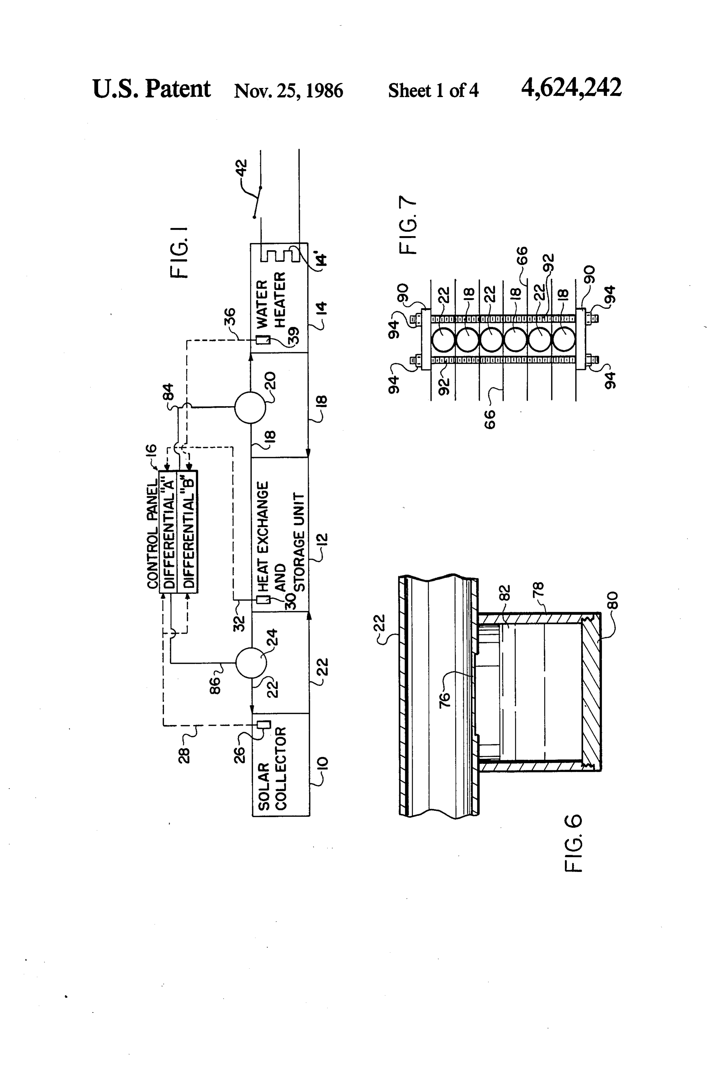
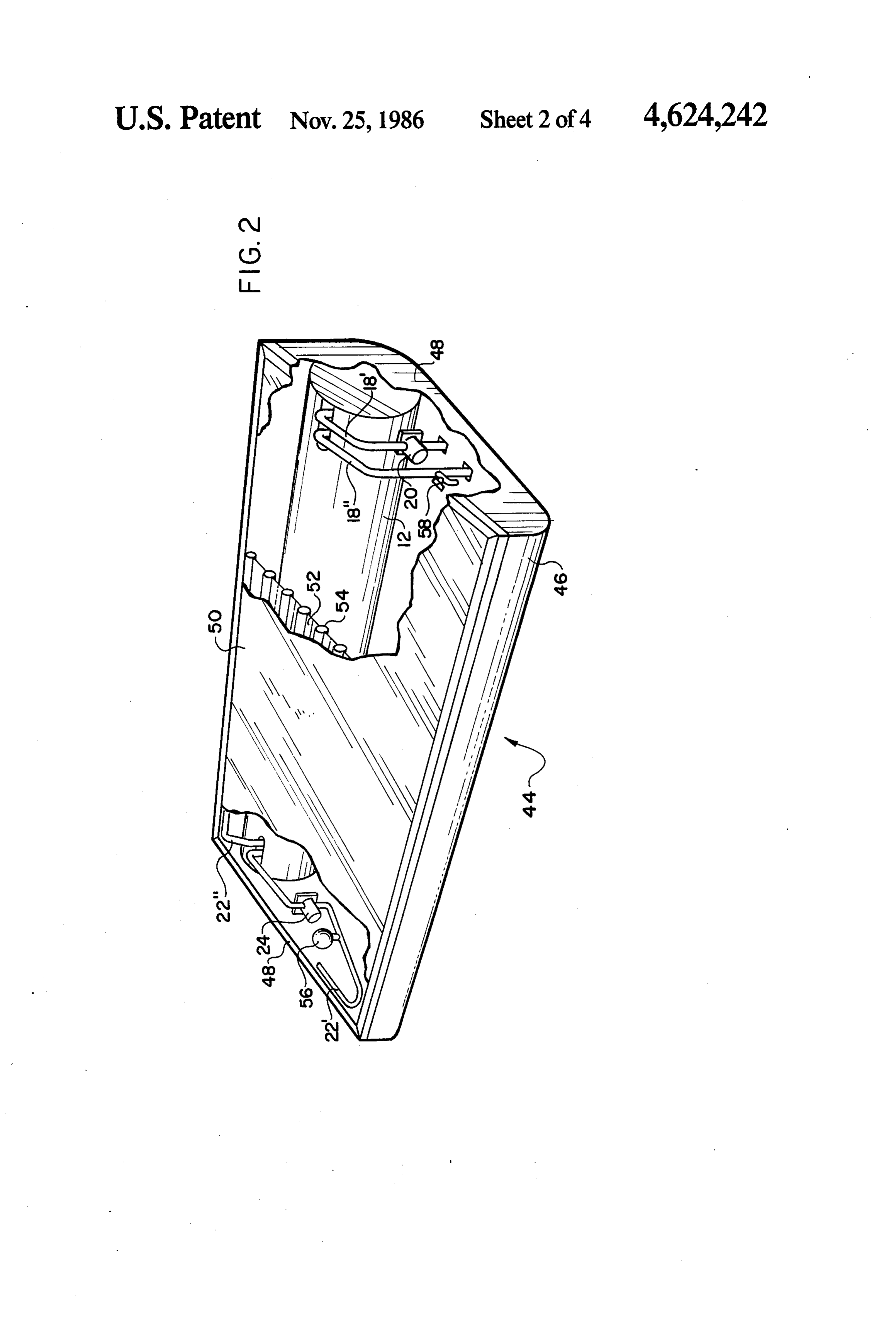
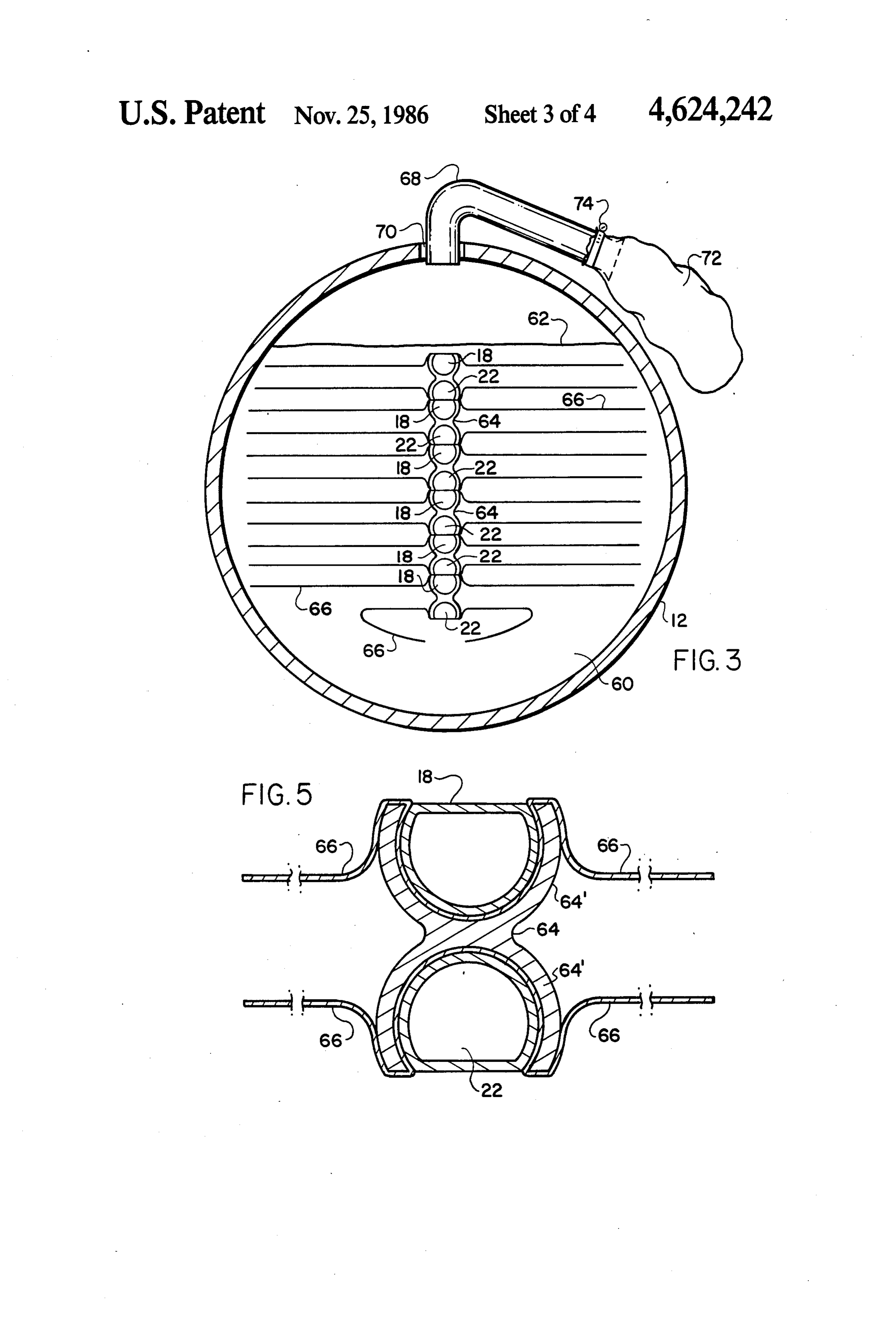
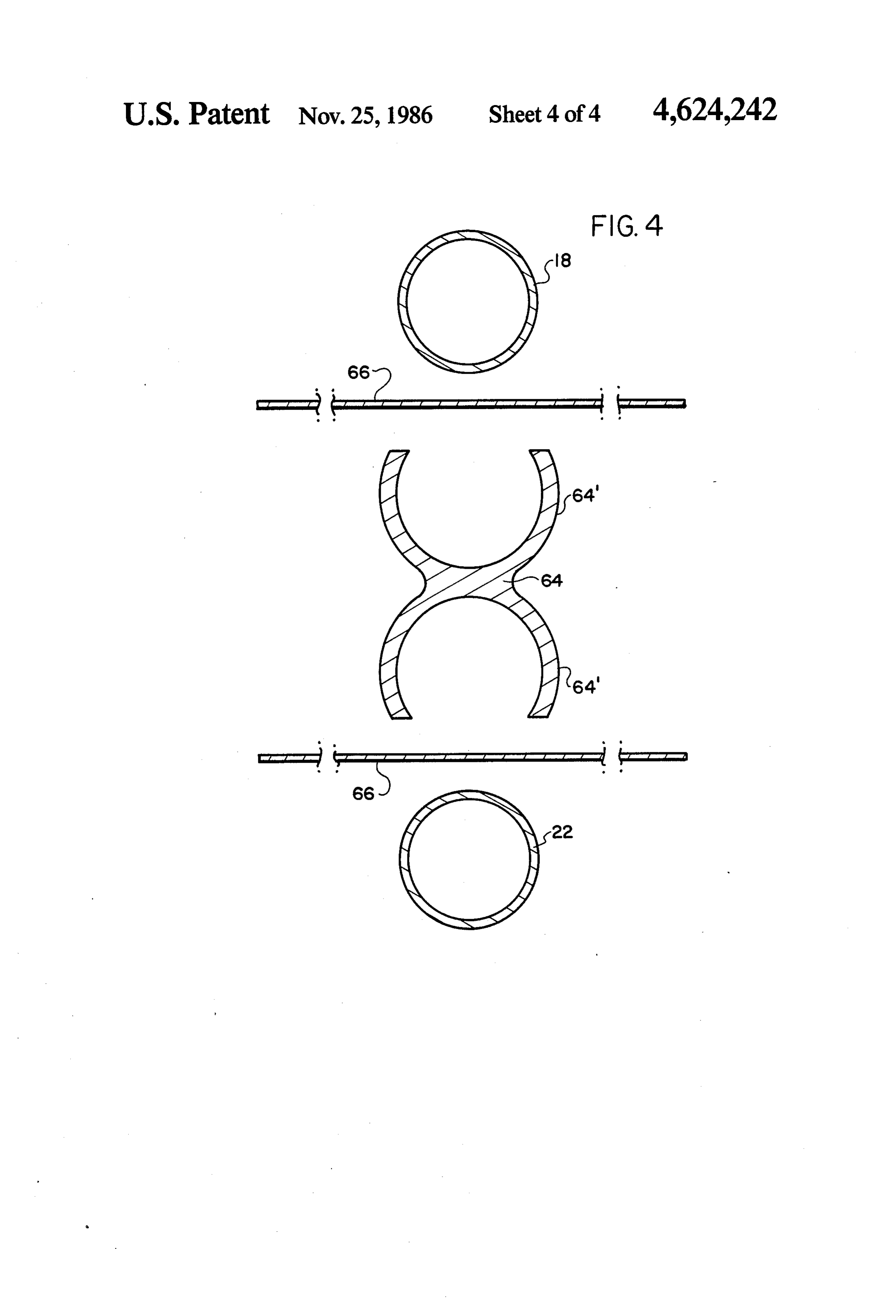
FIG. 6 is a detail view, in section, showing the seg unit 12 is carried in conduit leg 18", in which a relief ment of the collector conduit portion at which the alka valve 58 may be located.
Page 2drawing sheetscan →
Page 3drawing sheetscan →
Page 4drawing sheetscan →
Page 5drawing sheetscan →
Page 6scan →
the phase change material, it significantly increases the
SOLAR HEAT TRANSFER AND STORAGE manufacturing cost of the system because the relatively SYSTEM large number of thin, relatively closely spaced fins must be welded or otherwise individually fixed to the conduit
BACKGROUND OF THE INVENTION 5 at close spacings which require time-consuming and The present invention generally relates to heat trans skilled labor. The system of the present invention over fer and storage systems which may readily be incorpo comes the drawback of prior art arrangements by pro rated into conventional heating systems in order to viding a fin arrangement that can be fabricated quickly provide a heat collection and distribution system, pref 10 and at a relatively small cost, and that has a unique erably utilizing a solar collector panel for collecting interaction with a plurality of conduits for conducting solar heat energy. Electronic controls to command and heat transfer liquids therein.
regulate the various components of the system may be In solar systems of the type generally described included. The present invention is particularly directed above, some attention has been given to a control sys to a solar heat collection unit which utilizes a phase tem for increasing the efficiency of the system by shut change material to store collected solar heat within the 15 ting down the circulation of the fluid from the solar unit and a system utilizing such a unit as a component collector to the heat storage unit when the temperature part. in the solar panel liquid circuit in less than the tempera As used herein the term "phase change material' ture in the storage vessel. Thus, Saarem et al U.S. Pat. means any substance or combination of substances No. 4,191,166 discloses a closed system including a solar which, when changing state, have the property of re-20 collector, a storage tank and a pump which is controlled maining at substantially a constant temperature while to stop the circulation of the liquid flow from the collec absorbing or yielding up significant amounts of heat tor to the storage tank when the temperature of the energy. For example, H2O changes state, from liquid collector liquid is less than that in the storage tank, and (water) to solid (ice) or from solid (ice) to liquid (wa also to stop such circulation if the storage tank tempera ter), substantially at 32 degrees Fahrenheit (0 degrees 25 ture exceeds a predetermined limit. A somewhat similar Celsius). H2O will remain at a constant temperature control for a closed circulating system is disclosed in substantially at 32 degrees Fahrenheit until the change Buckley et al U.S. Pat. No. 4,399,807 where an auto of state is complete. Approximately 144 BTU will be matic overtemperature control is provided to protect absorbed by a pound of H2O during its change of state from ice to water and approximately 144 BTU will be 30 the collector in the event of the liquid circulation yielded up by a pound of H2O during its change of state through Kirts the collector falls below a predetermined limit.
U.S. Pat. No. 4,339,930 discloses a solar system from water to ice.
having a collector,
As used herein the term "paraffin waxes' means one changer, a heat pump, a domestic water heater, a heat ex or more phase change materials selected from the group somewhat complicatedandcontrol a thermal storage unit, and a system that operates of straight-chained hydrocarbon materials unusually 35 single pump for the entire system and a plurality of obtained by chilling paraffin distillate to remove the valves so that the fluid flow to and from the collector is heavy oils. These materials may generally be repre routed through the several aforesaid components of the sented by the chemical formula (CH(2n+2) where n system as a result of the differentials and relationship of equals from about 26 to about 30.
As used herein the term "latent heat' means the heat 40 the sensed temperature in the water heater, the collec per unit mass or mole required to produce a change of known tor and thermal storage system. In contrast to these phase of a given material at a constant temperature and control arrangements, the system of the present pressure. Often an adjective is added to specify the type invention includes a combined heat exchange and stor of phase transistion involved and the adjective "latent' the age unit, and separate fluid circuits for the collector and water heater which are independently controlled to is omitted, e.g. (latent) heat of evaporation, (latent) heat 45 significantly of sublimation, (latent) heat of fusion, etc. improve the efficiency of the overall sys As used herein the term "sensible heat' means the tem.
Another problem frequently encountered in solar heat absorbed per unit mass or mole of a given material collector in raising the temperature of the material without effect as paraffinsystems utilizing a phase change material such is the problem of properly containing the ing a change in the phase of the material. 50
Systems for collecting, storing and transferring solar phase change material while still providing an effective energy for utilization in conjunction with residential means for accommodating the substantial volumetric water heaters are well-known, and it is a known prac change of the phase change material when the phase tice to use a phase change material in such systems for change occurs (e.g., from solid to liquid, and from liquid the purpose of storing the energy of the sun as dis- 55 to solid). One known solution to this problem has been closed, for example, in Ashote U.S. Pat. No. 4,131,158 to encase the phase change material within the confines and Lindner et al U.S. Pat. No. 4,371,029. It is also of specially formed flexible tubular containers as dis known that when a phase change material is utilized, closed in Farfaletti-Casali et al U.S. Pat. No. 4,362,207 heat conducting fins may be provided within the phase or Wasserman U.S. Pat. No. 4,250,958, or to provide a change material to facilitate the transfer of heat to and 60 biased compression member that permits expansion and from such material as disclosed, for example, in the contraction of the phase change material while main aforesaid Lindner et al patent and in Hepp U.S. Pat. No. taining it under compression as disclosed in Van Heel 3,996,919. However, when such fins are used, it is con U.S. Pat. No. 4,270,523, or to load the phase change ventional practice to dispose the fins in parallel planes material into individual sealed pouches or bags formed extending radially from the conduit which conducts the 65 of a resilient plaster material as disclosed in Stice U.S. heated liquid, and into the phase change material. While Pat. No. 4,421, 101 and Cordon U.S. Pat. No. 4,367,788. this fin arrangement serves the desired purpose of in While all of these methods of containing the phase creasing the efficiency of the heat transfer to and from change material appear to protect the phase change 7 material from undesirable and potentially destructive duit portions, and the fins extend outwardly from the contact with ambient air while accommodating for the conduit portions in a plane extending parallel to the axes above-described volumetric variations in the phase of the conduit portions.
change material, they are also relatively expensive in In another embodiment, the conduit portions are terms of initial cost and installation. In the system of the arranged in a vertically stacked relationship with com present invention, a simple and effective arrangement is pression members disposed at the upper and lower ends provided which allows for significant volumetric varia of the stack, and rods are used to extend between the tions in the phase change material while still permitting compression members to hold the conduit portions in the material to be easily loaded into a rigid container place.
which is free of contamination by ambient air. O
The system of the present invention also includes a
Finally, solar collector systems often utilize certain unique control means that includes a first pump for types of heat transfer liquids other than water which are pumping the potable water through the first conduit, designed to increase the efficiency of the operation of and a first control for disenabling the first pump when the system, and some of these liquids, such as propyl the temperature of the potable water reaches a predeter glycol, will in time become acidic. When this happens, 15 mined maximum temperature. Also, a second pump is the acidic nature of the liquid will tend to cause deterio provided for pumping the heat transfer liquid through ration and corrosion of the conduits, fittings, seals and other components exposed to the liquid. Heretofore, the collector conduit, and a second control is provided which operates independently of the first control to this problem has been dealt with by the costly and time disenable the second pump when the temperature of the consuming procedure of periodically flushing the acidic 20 heat transfer liquid from the collector is equal to or less liquid from the system and replacing it with a fresh than the temperature of the phase change material, or supply, and, in some cases, the replacement of the fluid when is done only after the fluid has become acidic and dam reaches a predeterminedofmaximum the temperature the phase change material temperature.
age to the system components has already occurred.
The present invention provides a very simple and inex 25 In accordance with another feature of the present pensive addition which will automatically neutralize the invention, the conduit arrangement for the solar collec acid in the heat transfer liquid shortly after it become tor, which contains the heat transfer fluid, includes a acidic, without the necessity of flushing or replacing small segment in which a wall portion thereof has a such liquid. predetermined reduced thickness and is formed of a 30 material, preferably copper, that is soluble in acid. A
SUMMARY OF THE INVENTION container filled with an alkaline material is disposed at In accordance with the present invention, a heat the conduit segment immediately adjacent the reduced transfer and storage system is provided which can be thickness wall portion so that when the heat transfer readily connected to a source for utilizing the stored liquid, which is preferably propyl glycol, becomes heat, such as a conventional residential water heater. 35 acidic, the reduced thickness wall portion will be dis This system is highly efficient, easy to install and oper solved thereby and introduce the alkaline material into ate, and very inexpensive to build and install. the flow of the heat transfer liquid in the second conduit Briefly summarized, the system comprises a heat to neutralize the acid therein.
storage chamber having a phase change material Finally, the heat storage chamber in the system of the therein, a water heater that contains potable water and 40 present invention includes means for sealing the phase that includes a first conduit arrangement through which change material against exposure to ambient air, while the water flows, with a portion of the first conduit ex still accommodating the expansion and contraction of tending through the phase change material in the heat the phase change material within the chamber. The storage chamber, and a collecting unit for collecting chamber is partially filled with the phase change mate heat energy which includes a second conduit arrange 45 rial and the remaining portion of the chamber is filled ment having a portion thereof extending through the with a gaseous medium. The chamber includes a vent phase change material in the heat storage chamber in opening adjacent parallel relation to the aforesaid portion of the dium, andadjacent a sealed the area filled with the gaseous me expandable means, such as an ullage first conduit arrangement, such heat collecting unit bag, is fitted at the vent in sealed relation to the chamber preferably being a solar collector panel. Fins are pro 50 vided which extend outwardly from the adjacent paral to permit the gaseous medium to flow between the chamber and the sealed expandable means during ex lel portions of both the first and second conduit means pansion and into the phase change material to transfer heat be without and contraction of the phase change material exposing such material to ambient air.
tween such conduit portions and the phase change ma terial, and a connecting member formed of a high heat 55 BRIEF DESCRIPTION OF THE DRAWINGS conductivity material is preferably used to join the aforesaid first and second conduit portions together and andFIG. 1 is a diagrammatic view of the heat transfer storage system of the present invention;
to join the fins to such conduit portions, all in a heat FIG. 2 is a diagrammatic view of the solar panel conducting relationship.
In the preferred embodiment of the present invention, 60 incorporating therein various components of the system this connecting member is formed of a length of ex of the present invention;
truded aluminum having opposed curved recepticle FIG. 3 is a vertical sectional view taken through the portions for receiving the two conduit portions, and a center of the heat exchange and storage unit of the thin metal fin is interposed between one of the conduit present invention;
portions and the connecting member when the conduit 65 FIG. 4 is an exploded diagrammatic view of the con portion is pressed into the receptacle portion of the duit portions, fins and connector member therefor; connecting member. The fins having a lengthwise ex FIG. 5 is a view similar to FIG. 4 and showing the tent corresponding to the connected length of the con components thereof in their assembled portion;
Page 8scan →
FIG. 6 is a detail view, in section, showing the seg unit 12 is carried in conduit leg 18", in which a relief ment of the collector conduit portion at which the alka valve 58 may be located.
line receptacle is disposed; and As best illustrated in the vertical sectional view of FIG. 7 is a diagrammatic view of an alternate em FIG. 3, the heat exchange and storage unit 12 is par bodiment of the conduit portions, fins and connector 5 tially filled with a phase change material 60, preferably arrangement therefor. paraffin, up to a level indicated at 62 in its solid state, DESCRIPTION OF THE PREFERRED and portions of the two above-described conduit ar rangements 18 and 22 are completely immersed in the
EMBODIMENT paraffin 60, and arranged in a vertically stacked dispo The heat transfer and storage system of the present 10 sition, with the portions of conduit 18 being connected invention is diagrammatically illustrated in FIG. 1, and at their respective lengthwise ends to conventional inlet includes a solar collector unit 10, a heat exchange and and outlet headers (not shown) through which potable heat storage unit 12, a water heater 14, which may be, water is conducted to and from the water heater 14 for example, a conventional residential water heater through conduit legs 18' and 18" described above, and having its own heat source such as an electrical heating 15 with the portions of conduit 20 being similarly con element 14, and an electrical control panel 16. A first nected to inlet and outlet headers (not shown) through conduit arrangement 18 delivers potable water in the which the heat transfer liquid is conducted to and from water heater 14 to and from the heat exchange and the absorber plate 52 through conduit legs 22' and 22' storage unit 12, and a pump 20 is arranged to generate described above. As will be described in greater detail the flow of potable water. A second conduit arrange 20 below, the alternating portions of conduits 18 and 20 are ment 22 extends between the collector 10 and the heat joined together by connecting members 64, and a plu exchange and storage unit 12, and a second pump 24 is rality of fins 66 extend outwardly therefrom and into disposed to cause a flow of heat transfer liquid in the the surrounding paraffin 60. An opening is formed at the second conduit 22 to and from the heat exchange and top of the heat exchange and storage unit 12, and a storage unit 12 and the collector 10. A conventional 25 conduit 68 extends therethrough with a grommet 70 temperature sensing probe 26 is disposed in the collec being disposed about the conduit 68 to seal the opening tor 10 to sense the temperature of the heat transfer through which it extends so that ambient air will not liquid flowing therethrough, and this probe 26 is con pass into the interior of the heat exchange and storage nected by electrical line 28 to the two differential tem unit 12. One end of the conduit 68 terminates just below perature control portions of the control panel 16, desig 30 the grommet 70, and the other end thereof is connected nated as “Differential A' and "Differential B' in FIG. to a flexible bag 72, preferably formed of polyurethane, 1. A similar probe 30 is located in the heat exchange and a clamp 74 being provided to form an air-tight seal storage unit 12 to sense the temperature of the phase between the bag 72 and the conduit 68. It is well-known change material therein, and an electrical line 32 con that many phase change materials undergo a substantial nects the probe 30 with "Differential A,” and a third 35 volumetric increase when they change from their solid probe 39 senses the temperature of the potable water in state to a liquid state, and a corresponding substantial water heater 14 and is connected to “Differential B' by volumetric decrease when changing from liquid to sold. electrical line 36. The details of the operation of this For example, paraffin will experience a thirty-five per control panel 16 will be described in greater detail be cent increase in volume in going from - 40 degrees F. low. 40 to +250 degrees F. The above-described construction As illustrated diagrammatically in FIG. 2, all of the of the heat exchange and storage unit 12 provides a above-described components, except the control panel simple and unique arrangement for dealing effectively 16 and water heater 14, are conveniently and com and conveniently with this volumetric change of the pacted carried within a panel unit 44 that includes a phase change material. As shown in FIG. 3, the paraffin housing 46 formed with end panels 48 that support a top 45 60 occupies a major portion of the volume of the unit surface of glazing 50 and an absorber plate 52 disposed 12, and a gaseous medium is contained in the remaining just beneath glazing 50, the absorber plate 52 including area of the unit 12 above the level 62 of the paraffin 60. a plurality of pipes 54 extending along the length of the When the paraffin 60 expands upon sensible heat being panel unit 44. The heat transfer liquid is carried in the absorbed thereby, or upon a phase change from solid to pipes 54, alternate ones of which are connected at the 50 liquid, this expansion will simply cause the gaseous lengthwise ends thereof to inlet and outlet headers (not medium above the paraffin 60 to be passed through the shown), respectively, in a conventional manner well conduit 68 and into the bag 72 where it is retained at known in the art. The above-mentioned heat exchange virtually atmospheric pressure so as not to impede the and storage unit 12 is mounted in the housing 46, and is further flow of the gaseous medium into the bag 72 preferably in the form of a cylinder disposed beneath 55 during further expansion of the paraffin 60. Likewise, the absorber plate 52 as illustrated in FIG. 2. The flow volumetric contraction of the paraffin 60 is accommo of heat transfer liquid from the absorber plate pies 54 is dated in that the gaseous medium in the bag 72 can carried in conduit leg 22 to the heat exchange and readily flow back into the unit 12 through conduit 68. storage unit 12, and the flow of such liquid from the Since the unit 12 is sealed by grommet 70 and the bag 72 head exchange and storage unit 12 to the absorber plate 60 is sealed to conduit 68 by clamp 74 no ambient air, pipes 54 is carried in conduit leg 22", which also in which can cause undesirable deterioration of the paraf cludes the above-described heat transfer liquid pump 24 fin 60, is admitted to the unit 12 during expansion and and an expansion tank 56. The flow of potable water contraction thereof.
from the water heater 14 (see FIG. 1) to the heat ex The formation of the portions of conduits 18,22, the change and storage unit 12 is carried through conduit 65 connecting member 64, and the fins 66 is best illustrated leg 18", which includes the above-described potable in FIGS. 4 and 5. The connecting member 64 can be water pump 20 therein, and the flow of potable water to extruded aluminum, which makes them relatively inex the water heater 14 from the heat exchange and storage pensive to produce while also providing a connecting 9 unit that has high heat conductivity, and it will be noted paraffin 60, and to quickly conduct the stored heat in that each connecting member 64 consists of two op the paraffin 60 to the potable water in conduit 18 when posed pipe receiving portions 64, each formed on a the temperature of such water is less than the tempera radius and extending slightly beyond a half-circle. The ture of the paraffin.
fins 66 are extremely thin sheets of aluminum, prefera An alternate embodiment of the mounting arrange bly having a thickness of about 0.015 inch which is ment for the portions of the conduits 18,22 within the shown somewhat exaggerated in FIGS. 4 and 5 for heat transfer and storage unit 12, and the fins 66 is illus clarity of illustration, and they have an extending length trated in FIG. 7. In this embodiment, the conduits 18,22 corresponding generally to the length of the cylindrical are stacked alternatively as a vertical bank, and one of housing of the heat transfer and storage unit 12 and a 10 the fins 66 is interposed between each two adjacent varying width, as shown in FIG. 3, so that they will conduit portions and at the two end conduit portions in extend outwardly from the portions of conduits 18,22 to direct, heat conducting contact therewith. To hold the a point slightly spaced from interior surface of such conduit portions 18,22 and fins 66 in place, a connecting housing. To join the aforesaid elements together, they system is provided which includes a pair of compression are initially held in place in the general disposition 15 blocks 90 located adjacent the uppermost and lower shown in FIG. 4 by a jig or other suitable means, with most fins 66, and a pair of connecting rods 92 being the portions of conduits 18 and 22 disposed in spaced threaded to receive nuts 94 thereon. It is to be appreci relation to the two receiving portions 64 and with a fin ated that the tightening of the nuts 94 will compress the 66 disposed between each conduit portion and the re entire arrangement of the portions of conduits 18,22 and ceiving portions 64". A press is then utilized to force the 20 the fins 66 to hold them in place as illustrated in FIG. 7, portions of conduits 18 and 22 into the opposed receiv and the compression force generated by the rods 92 and ing portions 64 so that they are held in place thereby, nuts 94 will insure that these elements are maintained in with the thin fins 66 being bent to conform to the curva a heat conducting relationship. Again, this alternate tures of the conduits and the receiving portions 64 so embodiment offers an inexpensive and effective mount that they are interposed therebetween and held in place 25 ing arrangement for the portions of the conduits 18,22 thereby. As part of this pressing operation, the portions and the fins 66 which can be easily mounted within the of the conduits 18 and 22 extending beyond the opposed heat transfer and storage unit 12 to provide a rapid and receiving portions 64 may be flattened as shown in effective transfer of heat between the paraffin 60 and FIG. 5, which provides two advantages. First, these flat the conduits 18 and 22.
surfaces permit the individual two-pipe conduit units to In accordance with another feature of the present be stacked atop one another in a vertical disposition as invention, the heat transfer liquid conduit 22 is formed shown in FIG. 3 with the adjacent flat surface offering with a specially formed segment that can be used with a sufficient support so that all of the portions of the heat transfer liquids, such as propyl glycol, that may conduits 18 and 22 can be held in place within the unit become acidic over time and cause damage to the sys 12 by their connection to the aforesaid inlet and outlet 35 tem as discussed above. FIG. 6 illustrates a segment of headers within the unit, and without requiring any ex conduit 22 which may be located at any exposed por pensive welding or other joining of the composite units tion thereof, and which includes a wall portion 76 that that would be inherently difficult. Additionally, in their has a predetermined reduced thickness as compared stacked disposition as shown in FIG. 3, it will be ob with the normal thickness of the conduit 22, and which served that the flat portions of conduit 18 are disposed 40 is formed of a material that is readily soluble in acid, immediately adjacent the corresponding flat portions of such as copper. A receptacle 78 is fitted on the conduit conduit 22 so that there is a significantly increased area 22 and disposed immediately adjacent the wall portion of mutual contact between the two conduits as com 76, and a threaded cap 80 is provided at the extending pared with the tangential contact of adjacent cylindrical end of the receptacle 78 which can be removed to fill or conduits, and there is a resulting significant increase in 45 partially fill the receptacle with an alkaline material 82 the heat exchange that will occur between the heat and which, when closed, seals the receptacle 78. If the transfer liquid conveyed in conduit 22 and the potable heat transfer liquid in conduit 22 becomes acidic, the water conveyed in conduit 18. Apart from these advan acid will dissolve the thin wall portion 76 and the alka tages, it will also be appreciated that simple and rela line material 82 in the receptacle 78 will then be released tively inexpensive assembly of the conduits 18,22 and 50 into the flow of the heat transfer liquid in conduit 22 and the fins 66 offer a substantial improvement over the neutralize the acid therein. Since the receptacle 78 is conventional method of attaching fins to conduits by sealed, the rupture of the thin wall portion 76 will not individually welding the fins to the conduits in spaced result in any leakage of the heat transfer liquid from the relation along the length of the conduits and with the conduit 22, and the disposition of the receptacle 78 fins extending outwardly from the conduits in radial 55 about the thin wall portion 76 will provide protection planes, all of which involved a time-consuming and therefor so that it cannot be inadvertently ruptured expensive assembly procedure. Moreover, in the ar during handling, installation and use.
rangement of the present invention, it will be noted that The operation of the above-described solar heat two fins 66 extend outwardly from each pair of joined transfer and storage system is as follows. The solar conduits 18,22 in planes extending parallel to the axes 60 panel unit 44 is placed at a convenient location (e.g. on thereof, and that there is a substantial area of conduit a roof or on the ground) where it will be exposed to the between the fins 66, the conduits 18,22 and the heat sun's rays, and the solar heat will be absorbed by the conducting connecting members 64 along the entire absorber plate 52 to heat the heat transfer liquid in the extending lengths thereof which significantly increases pipes 54. The pump 24 will cause the heat transfer liquid the capacity of the fins 66 in carrying out their intended 65 to flow through the conduit arrangement 22 and the function, namely to quickly conduct heat from the con portions thereof immersed within the paraffin 60 in the duit 22 to the paraffin 60 for storage when the tempera heat transfer and storage unit 12. At the same time, the ture of the heat transfer liquid is greater than that of the potable water in the water heater 14 is conveyed by.
Page 10scan →
pump 20 through the conduit arrangement 18 and the ture of the paraffin 60 through probe 30 and electrical portions thereof immersed in the paraffin 60, which line 32, and receives the sensed temperature of the heat preferably is selected to have a melting temperature that transfer liquid through probe 26 and electrical line 28. corresponds generally to the desired high temperature The pump 24 is normally operating to cause flow of the for the potable water in the water heater 14 (e.g. in the heat transfer liquid through the conduit 22 as described range of 110-150 F., preferably about 115 F). As above, but when "Differential A' determines that the suming that the temperature of the heat transfer liquid is temperature of the heat transfer liquid is equal to or less greater than that of the paraffin 60 or the potable water than that of the paraffin 60, it will generate a control in the water heater 14, and assuming that the tempera signal through electrical line 86 to disenable or shut ture of the paraffin 60 is below its melt point, it will be 10 down pump 24 so that the flow of the heat transfer appreciated that most of the heat in the heat transfer liquid through the system is discontinued. Also, the liquid is conducted directly and quickly to the potable "Differential A' control may be programmed to disen water by virtue of the contracting and heat conducting able pump 24 at any time the temperature of the paraffin disposition of the portions of conduits 18,22 as shown in 60 reaches a predetermined maximum temperature (e.g. FIG.3 and described above so that the potable water in 15 150 F.) This cutoff of the pump 24 is provided because the water heater 14 is quickly elevated. Moreover, some of the temperature if the temperature of the paraffin of the heat in the heat transfer liquid is absorbed by the exceeds the predetermined maximum level, it will cause paraffin 60 in sensible heat fashion by virtue of the im excessive expansion of the paraffin, and will cause large mersion of the portions of conduit 22 in the paraffin 60 heat loss to the ambient air which results in less efficient and the increased conduction of such heat to the paraf 20 heat storage.
fin 60 through the large surface area provided by the The "Differential B," which operates independently plurality of fins 66. During this phase of the operation, of "Differential A', receives the sensed temperature of the paraffin 60 is in a solid state and while it absorbs the heat transfer liquid from probe 26 and the sensed some sensible heat, it primarily acts as a heat insulator so temperature of the potable water in the water heater 14 that, as noted above, the heat in the heat transfer liquid 25 through probe 34. The pump 20 is normally operable to is transmitted directly to the potable water to raise the cause flow of the potable water through conduit 18, but temperature thereof at a relatively rapid rate. when "Differential B" determines that the temperature When the temperature of the potable water reaches of the potable water is greater than the temperature of the aforesaid desired temperature (e.g. 115 F.), which the paraffin 60, the pump 20 is disenabled by a control corresponds generally to the melt point of paraffin 60, 30 signal transmitted through electrical line 84. Also, "Dif. the additional heat conveyed to the paraffin 60 will ferential B' is set to disenable the pump 20 at any time begin its phase change from solid to liquid, and during the potable water in the water heater 14 reaches a pre this phase change virtually all of the heat in the heat determined maximum temperature (e.g. 170 F). transfer liquid is transmitted in latent heat fashion to the Since the conduit arrangement 18 for the potable paraffin 60, and very little of this heat is transmitted to 35 water is independent of the conduit arrangement 22 for the potable water which has now reached its predeter the heat transfer liquid, and since the respective pumps mined desired temperature. As the paraffin 60 begins to 20 and 24 are also independently controlled by "Differ melt in the unit 12, the liquid portion moves around ential A" and "Differential B", the system of the present within the unit 12 and about the portion of conduit 22 to invention can be operated with unusually high effi facilitate further the rapid transfer of heat to the paraf 40 ciency and with great flexibility of use. For example, fin. During this phase of the operation, most of the heat when absorber plate 52 is collecting large amounts of in the heat transfer liquid is conveyed to, and effectively solar energy during bright sunshine, this heat will be stored in, the paraffin 60, and this continues for as long conducted primarily to the potable water if the temper as the temperature of the heat transfer liquid is greater ature thereof is below its desired temperature, or will be than that of the paraffin, or until the pump 24 is disen 45 conducted primarily to the paraffin 60 for storage if abled by the control panel 16 if a predetermined maxi heating of the potable water is not required. Thus, in a mum temperature is reached as described below. typical application of the system to heat the water in a When the temperature of the heat transfer liquid residential water heater, such water is normally not drops below that of the paraffin 60, or that of the pota used during the middle of the day and the pump 20 will ble water, such as at night when no solar heat is being 50 normally be disenabled during such times because the absorbed by the absorber plate 52, the pump 24 is disen potable water has reached its predetermined desired abled and there is no further flow of the heat transfer temperature. Since the pump 20 is disenabled, there will liquid through the conduit 22. Because, however, of the be no flow of the potable water through the poriton of large amount of heat stored in the paraffin 60, if the conduit 18 within the heat transfer and storage unit 12, temperature of the potable water drops below its de 55 and, therefore, there will be little heat exchange within sired level, the pump 20 will cause a flow of the potable such unit 12 even through the portion of the conduits 18 water through the heat transfer and storage unit 12 so and 22 in a heat conducting relationship within the unit that it will absorb the stored heat in the paraffin 60 12, and virtually all of the heat absorbed by the absorber which is conducted to the potable water through the plate 52 will be stored in the paraffin for subsequent use. fins 66 and the portion of the conduit 18 immersed in the 60 If, however, the hot water in the water heater 14 should paraffin. During this phase, the paraffin 60 may be in a be used during the daytime period, the temperature of liquid state so that the conduction of heat to the potable the potable water will normally drop to a point at which water is rapid. pump 20 is cut on, and the potable water will then flow The control of the flow of the heat transfer liquid and through the portion of conduit 18 disposed in heat con the potable water by the pumps 24 and 20, respectively, 65 ducting relationship to the portions of conduit 22 so that is carried out by the control panel 16. "Differential A', available heat in the heat transfer liquid will be con which is a convention temperature differential sensing ducted primarily to the potable water to quickly raise and control component, receives the sensed tempera the temperature thereof rather than primarily storing 11 the available heat in the paraffin 60. Moreover, during viding a full and enabling disclosure of the invention. times when little or no solar heat is available, such as The foregoing disclosure is not intended or to be con during the night or during cloudy portions of the day, strued to limit the present invention or otherwise to the pump 24 will normally be disenabled, but if heat is exclude any other embodiment, adaptations, variations, needed to raise the temperature of the potable water, modifications and equivalent arrangements, the present pump 20 will be operating to cause flow of the potable invention being limited only by the claims appended water through the paraffin 60 whereby available stored hereto and the equivalents thereof.
heat therein is utilized to heat the potable water, and I claim:
there is little or no heat loss to the heat transfer liquid in 1. A heat transfer and storage system comprising: conduit 22 because it is not flowing. 10 (a) a heat storage chamber having a phase change To summarize the above, it will be observed that the material contained therein; control system operates as follows: (b) water heater means for containing potable water, (a) When solar energy is available and heat is needed and including first conduit means through which to raise the temperature of the potable water, both said water flows, said first conduit means having a pumps 20 and 24 are operable to obtain maximum 15 portion thereof extending through said phase direct heat exchange from the heat transfer liquid change material in said chamber; to the potable water, with only a small amount of (c) means for collecting heat energy, and including such available heat being stored in the paraffin. second conduit means through which a heat trans (b) When solar energy is available and heat is not fer liquid flows, said second conduit having a por needed for the potable water, pump 20 is disen 20 tion thereof extending through said phase change abled and pump 24 is operated to cause maximum material in said chamber in adjacent parallel rela storage of the available heat in the paraffin, with tion to said portion of said first conduit means; little or no transfer of heat to the dormant potable (d) fin means extending outwardly from said portions water circuit. of said first and second conduit means to transfer (c) When solar energy is not available and heat is 25 heat between said conduit portions and said phase needed to raise the temperature of the potable wa change material; and ter, pump 24 is disenabled and pump 20 will be (e) connecting means simultaneously holding said operated any time stored heat is available from the portions of said first and second conduit means in paraffin, with little or no heat loss to the dormant adjacent heat conducting relationship to one an heat transfer liquid. 30 other and holding said fin means interposed be (d) When solar energy is not available and when there tween said portions of said first and second conduit is no available stored heat in the paraffin, both means in a heat conducting relationship therewith. pumps 20 and 24 are disenabled and heat can be 2. A heat transfer and storage system as defined in obtained from the heating element 14 of the water claim 1 and further characterized in that said means for heater to essentially the same extent as would be 35 collecting heat energy comprises solar collector means possible if the auxiliary solar system of the present for collecting solar heat energy.
invention were not being used. 3. A heat transfer and storage system as defined in Thus, the independent conduit arrangement for the claim 2 and further characterized in that said fin means potable water and the heat transfer liquid, and the inde extend outwardly from said portions of said conduits in pendent control for each of these circuits, when com 40 a plane extending parallel to the axes of said conduit bined with heat exchange relationship of the portion of portions.
conduits 18 and 22 immersed in the paraffin, provides a 4. A heat transfer and storage system as defined in system which is highly efficient and which responds claim 2 and further characterized in that said connect quickly to the varying requirements of the user and the ing means is formed of a material having high heat varying conditions of the system itself. 45 conductivity, and in that said connecting means extends As indicated above, the preferred embodiment of the along the length of said conduit.
present invention utilizes a solar collector panel for 5. A solar heat transfer and storage system as defined collecting solar energy which is then stored, but it will in claim 2 and further characterized in that said fin be appreciated that the system of the present invention means constitutes thin metal sheets interposed between could also use other sources for collecting heat energy 50 said portions of said conduit means and connecting in lieu of the solar panel, such as conventional electrical means, and held in place thereat by said portions of said energy obtained during off-peak demand time periods conduit means being pressed into said connecting means or waste industrial heat, and many of the advantages of for retention thereby.
the present invention would still be realized. 6. A heat transfer and storage system as defined in It will therefore be readily understood by those per 55 claim 5 and further characterized in that said connect sons skilled in the art that the present invention is sus ing means is a length of metal formed with opposed ceptible of a broad utility and application. Many em curved receptacle portions extending lengthwise bodiments and adaptations of the present invention thereof for receiving said first and second conduit por other than those herein described, as well as many vari tions, respectively, with said fin means being interposed ations, modifications and equivalent arrangements will 60 between said connecting member and at least one of be apparent from or reasonably suggested by the pres said conduit portions along the lengthwise extent ent invention and the foregoing description thereof, thereof.
without departing from the substance or scope of the 7. A heat transfer and storage system as defined in present invention. Accordingly, while the present in claim 2 and further characterized in that said first and vention has been described herein in detail in relation to 65 second conduit means are arranged serially with their its preferred embodiment, it is to be understood that this axes disposed in a common plane and with said fin disclosure is only illustrative and exemplary of the pres means interposed therebetween, and in that said con ent invention and is made merely for purposes of pro necting means includes holding elements disposed at the 12 respective ends of said serially arranged conduit means through said second conduit means, whereby said and compression means for urging said holding ele collected energy in said second conduit means is ments toward one another to hold said conduit means transfered to said phase change material; and said fin means in place therebetween. (d) first control means for disenabling said first pump 8. A heat transfer and storage system as defined in means when the temperature of said potable water claim 2 and further characterized in that first and sec reaches a predetermined maximum temperature; ond pump means are provided for causing fluid flow (e) second control means for disenabling said second through said first and second conduit means, respec pump means when the temperature of said fluid in tively; in that a first control means is provided for disen said second conduit means is equal to or less than abling said first pump means when the temperature of 10 the temperature of said phase change material; and said potable water reaches a predetermined maximum (f) third control means for disenabing said first pump temperature; and in that second control means is pro means when the temperature of said potable water vided for disenabling said second pump means when the is greater than the temperature of said phase temperature of said fluid in said second conduit means is change material.
equal to or less than the temperature of said phase 15 15. A heat transfer and storage system as defined in change material. claim 14 and further characterized in that said means for 9. A heat transfer and storage system as defined in collecting heat energy comprises solar collector means claim 8 and further characterized in that said second for collecting solar heat energy. control means disenables said second pump means when 16. A heat transfer and collection system as defined in the temperature of said phase change material reaches a claim 15 and further characterized in that said first and predetermined maximum temperature. 20 second conduit means extend through said phase 10. A heat transfer and storage system as defined in change material in contacting relationship to one an claim 8 and further characterized in that said first con other, and in that a plurality of heat conducting fin trol means disenables said first pump when the tempera means are arranged in heat conducting contact with ture of said potable water is equal to or greater than the said first and second conduit means and extend out temperature of said phase change material. 25 wardly therefrom and into said phase change material 11. A heat transfer and storage system as defined in to conduit heat between said first and second conduit claim 2 and further characterized in that said second means and said phase change material. conduit means includes a segment in which a wall por 17. A heat transfer and collection system as defined in tion thereof has a predetermined reduced thickness and claim 16 and further characterized in that said first and is formed of a material that is soluble in acid; in that the 30 second conduit means include portions thereof that are heat transfer liquid in said second conduit means is a arranged in parallel contacting relationship. liquid which tends to become acidic with the passage of 18. A heat transfer and collection system as defined in time; and in that a sealed receptacle containing an alka claim 15 and further characterized in that said second line material is disposed at said conduit segment imme control means disenables said pump means when the diately adjacent said reduced thickness wall portion, 35 temperature of said fluid pumped in second conduit whereby when said heat transfer liquid becomes acidic means reaches a predetermined maximum temperature. said wall portion will be dissolved thereby and intro 19. A heat transfer and collection system as defined in duce said alkaline material into the flow of said heat transfer liquid in said second conduit means. claim 15 and further characterized in that said phase 12. A heat transfer and storage system as defined in change material has a predetermined melting tempera claim 11 and further characterized in that said wall 40 ture within the range of 110-150 degrees F. 20. A heat transfer and storage system comprising:
portion is formed of copper, and in that said heat trans (a) a heat storage chamber having a heat transfer fer liquid is propyl glycol. material contained therein; 13. A heat transfer and storage system as defined in (b) water heater means for containing potable water, claim 2 and further characterized in that said heat stor age chamber is a rigid container partially filled with a 45 and including first conduit means through which phase change material that expands when heated, with said water flows, said first conduit means having a the remaining portion of said heat storage chamber portion thereof extending through said heat trans being filled with a gaseous medium; in that said heat fer material in said chamber; storage chamber includes a vent opening adjacent the (c) means for collecting heat energy, and including area containing said gaseous medium; and in that a 50 second conduit means through which a heat trans sealed expandable means is fitted at said vent to permit fer liquid flows, said second conduit having a por said gaseous medium to flow between said heat storage tion thereof extending through said heat transfer chamber and said sealed expandable means during ex material in said chamber in adjacent parallel rela pansion and retraction of said phase change material tion to said portion of said first conduit means; without exposing said phase change material to ambient 55 (d)offinsaid means extending outwardly from said portions first and second conduit means to transfer
14. A heat transfer and collection system, comprising: heat between said conduit portions and said heat (a) a heat storage chamber having a phase change transfer material; and material contained therein; (e) connecting means simultaneously holding said (b) water heater means for containing potable water, 60 portions of said first and second conduit means in and including first conduit means extending adjacent heat conducting relationship to one an through said phase change material in said heat other and holding said fin means interposed be storage chamber and first pump means for moving tween said portions of said first and second conduit said potable water through said first conduit means in a heat conducting relationship therewith. means; 2. A heat transfer and storage system as defined in (c) means for collecting heat energy, and including 65 claim 20 and further characterized in that said means for second conduit means extending through said collecting heat energy comprises solar collector means phase change material in said heat storage cham for collecting solar heat xk k energy.
ber, and second pump means for pumping a fluid
Provenance
- Collection
- Patents citing this work
- Pages
- 12
- Method
- pdftotext (the PDF's own text layer) + pdftoppm 300dpi page scans
- Patent office record
- patents.google.com →
- Source
- Google Patents citing-documents table
- Assignee
- Examplar
- Published
- 1986-11-25
- Transcribed from
- patentimages.storage.googleapis.com →