

patent · US4626448A
Plasma deposition of amorphous metal alloys
2 December 1986
Text
Page 1scan →
United States Patent (19)
Hays
(54) plasma deposition of amorphous
Metal alloys
75 Inventor: Auda K. Hays, Albuquerque, N.
73 Assignee: The United States of America as represented by the United States
Department of Energy, Washington,
51) Int. C. ............................................... B05D 3/06 52 U.S. Cl. ................................ 427/39; 204/164.165
3,677,799 11/1970 Hou ................................. 204/164X 3,900,585 8/1975 Matsubara ............................. 427/13 3,904,366 9/1975 Grasenick .... 204/164 X 3,907,616 9/1975 Wiemer ........ ... 148/188 3,968,270 7/1976 Hasegawa ............................. 427/13 4,099,969 7/1978 Leder ........... 204/164X 4,262,631 4/1981 Kubacki .............................. 118/723 4,321,126 3/1982 Kieferle et al. ..................... 204/298
4,394,400 7/983 Green et al. .......................... 427/38 4,400,410 8/1983 Green et al. .......................... 427/39 4,406,765 9/1983 Higashi et al. ...................... 204/164
Other publications
Lieberman, H. H., "Amorphous Alloy Sample Prepara tion-Methods and Process Characterization,' General Electric Report #82CRD146, May 1982.
Lieberman et al., "Rapid Solidification of Metastable Material,” G.E. Report #81CRD327, Jan. 1982.
Wroge, D. M. et al., "Plasma Enhanced Deposition of Iron/Iron Oxide Films,” Report 1979, LBL 9879.
Primary Examiner-Bernard D. Pianalto
Attorney, Agent, or Firm-Armand McMillan; Albert
Sopp, Judson R. Hightower
Amorphous metal alloy coatings are plasma-deposited by dissociation of vapors of organometallic compounds and metalloid hydrides in the presence of a reducing gas, using a glow discharge. Tetracarbonylnickel, phos phine, and hydrogen constitute a typical reaction mix ture of the invention, yielding a NiPC alloy.
6 Claims, 1 Drawing Figure
Rf power
Supply
Pasma
Reactor
Drawings
Page 2drawing sheetscan →
Page 3scan →
In view of the prior art and its limitations, it is an
PLASMA DEPOSITION OF AMORPHOUS METAL object of this invention to provide a novel technique to ALLOYS produce amorphous metal alloy coatings. Another ob ject is to provide a technique that does not require large
BACKGROUND OF THE INVENTION 5 quantities of energy to produce such coatings. A further object is to develop a technique for application of amor
The U.S. Government has rights in this invention phous metal alloy coatings that does not require heating pursuant to Contract No. DE-AC04-76DP00789 be the substrate above room temperature.
tween the U.S. Department of Energy and the AT&T Still another object is to produce adherent amor Technologies, Inc. 10 phous metal alloy coatings. A further object is to pro This invention relates to amorphous metal alloy coat vide a technique which can be easily and inexpensively ings. More particularly, it relates to a novel technique varied to apply multi-component amorphous metal for producing a variety of amorphous metal alloy coat alloy coatings. A further object of this invention is to ings on a variety of substrates of different sizes and provide a technique which additionally can be used to shapes. 15 coat large, irregularly-shaped objects in a uniform man Three methods have conventionally been used to ner with amorphous metal alloy coatings.
produce amorphous metal alloys of high strength, ex Additional objects, advantages, and novel features of cellent corrosion and abrasion resistance, namely rapid the invention will be set forth in part in the description solidification, sputtering and electroless chemical depo which follows, and in part will become apparent to sition. 20 those skilled in the art upon examination of the follow The rapid solidification method is well described by ing or may be learned by practice of the invention. The H. H. Liebermann and J. L. Walters in "Rapid Solidifi objects and advantages of the invention may be realized cation of Metastable Materials,' General Electric Re and attained by means of the instrumentalities and com port No. 81CRD327 (January 1982), and by H. H. Lie binations particularly pointed out in the appended bermann in "Amorphous Alloy and Sample Prepara 25 claims.
tion-Methods and Process Characterization,' General SUMMARY OF THE INVENTION Electric Report No. 82CRD146 (May 1982). Rapid solidification has been found practical for the produc In accordance with the invention, amorphous metal tion of ribbons and wires of amorphous metal alloys. alloy coatings are plasma-deposited on substrates by However, the process requires relatively large expendi 30 dissociating organometallic compounds and metalloid tures of energy for melting the alloy to be coated and hydride vapors in a reducing carrier gas, preferably can only be carried out with substrates capable of with hydrogen, in a glow discharge environment. The standing the high temperatures involved with the liquid plasma in the glow discharge is characterized by an metal alloys used prior to the subsequent super-cooling. average electron energy of 1 to 10 eV and electron Adhesion of the splat-cooled coatings produced is also 35 densities of 109 to 1012 cm-3. Energy to initiate and a problem. sustain the discharge may be supplied at frequencies For these reasons, coatings of amorphous metal al ranging from 0 to 1010 Hz. This energy may be coupled loys are generally produced by sputtering or electroless into the discharge either inductively, capacitively, or chemical deposition. The sputtering technique is briefly directly.
described in Liebermann's Report No. 82CRD146, One or more different organometallic compounds along with other coating methods which include elec and metalloid hydrides may be used to form a given tron beam surface melting. The sputtering technique film, but in any case the concentration and supply of the has limitations. One of them is the difficulty and expense gaseous hydride component provided to the reaction involved in fabricating sputtering targets for multi-com mixture must be maintained at such a level that the ponent metal alloys. Each target has to be uniquely 45 metalloid content of the final metal alloy coating ranges formulated to take into account the diffusion time of the between about 20 and about 40 atomic percent in order individual metal or metalloid atoms, as well as the stick for the alloy to be amorphous and yet possess metallic ing coefficients of these atoms to the surface to be properties.
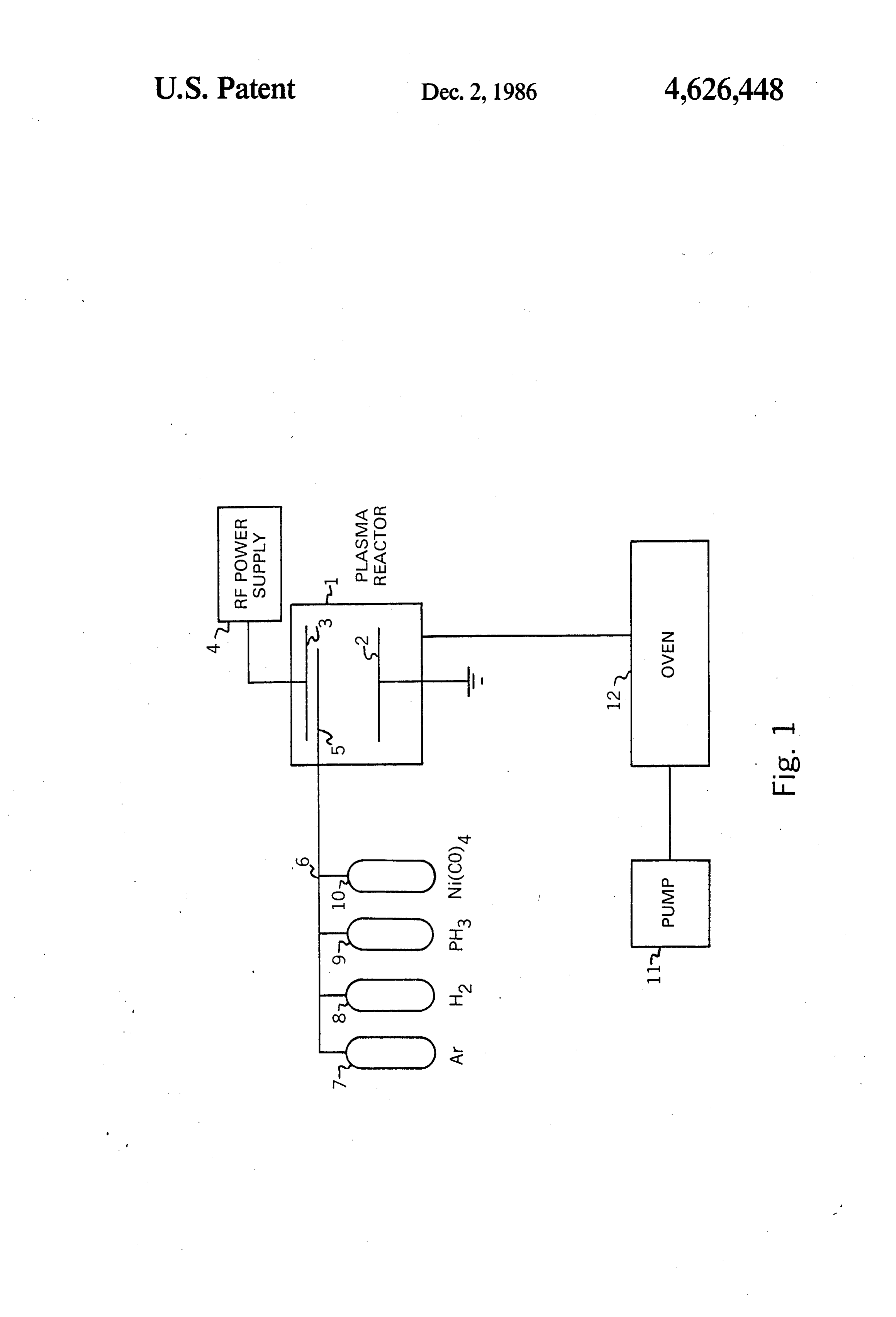
coated. Small changes in alloy formulation to optimize a particular material property, e.g., corrosion resis 50 BRIEF DESCRIPTION OF THE DRAWING tance, require the fabrication of a new target. Another FIG. 1 shows, in schematic representation, a type of limitation, although not as severe, lies in coating of apparatus that can be used to carry out the technique of large, complex shapes uniformly. Sputtering is primar the invention.
ily a line-of-sight process and, as such, tends to have DETAILED DESCRIPTION OF THE
Invention
An electron beam evaporation process has been de scribed by K. Matsubara (U.S. Pat. No. 3,900,585) for The plasma deposition technique used to produce coating a solid metal onto a substrate. In that process, amorphous metal alloy coatings according to the inven however, the substrate must serve as cathode and, tion consists of dissociating mixtures of organometallic therefore, must be conductive, and the resulting coat 60 compounds and metalloid hydrides in various carrier ings are not amorphous. Iron also can be coated onto a gases in the presence of a radio-frequency discharge. substrate by a plasma-enhanced deposition method in Thus, the metal atoms in the final coating are pro volving the decomposition of iron pentacarbonyl in a vided by compounds such as metal carbonyls, metal radio frequency power-induced glow discharge reactor, alkyls, metal alkoxides, or metallocenes. Typical usable but again the resulting coating consists of iron crystal 65 compounds within these classes include bis(cyclopen lites embedded in an iron oxide matrix (D. M. Wroge tadienyl)magnesium, dibenzenechromium, dimethyl and D. W. Hess, "Plasma-enhanced Deposition of Iron cadmium, diethyltelluride, diethylzinc, pentacarbonyli ron, tetracarbonylnickel, tricarbonylnitrosylcobalt, tri /Iron Oxide Films,” Report LBL-9879, 1979).
Page 4scan →
isobutylaluminum, trimethylaluminum, trimethylan as a liquid stored under carbon monoxide. The carbon timony, trimethylarsenic, trimethylgallium, trimethylin monoxide was removed by repeated freeze-pump-thaw dium, tungsten hexafluoride, and the like. The metalloid ing of the nickel carbonyl cylinder. The room tempera atoms, on the other hand, are provided by their corre ture vapor pressure of the nickel carbonyl was sufficient sponding hydrides. A typical and preferred example of 5 to provide the quantities required for the preparations. this type of gaseous compound is phosphine. Formation Because of the extreme toxicity of nickel carbonyl, of an amorphous metal alloy coating also requires the the entire preparation was carried out in a fume hood. presence of a reducing carrier gas, e.g., hydrogen, in The gaseous effluent from the reaction mixture was order to avoid the incorporation of undesirable species rough-pumped through an oven downstream of the in the film, e.g., metal oxides. 10 plasma reactor, as explained in the drawing. The oven An apparatus that can be used to carry the process of was maintained at 450° C., a temperature sufficient to the invention is shown in FIG. 1. As can be seen on the dissociate any unreacted nickel carbonyl at the pres schematic diagram, plasma reactor 1 is equipped with sures and pumping speeds used. In addition, the room grounded liquid-cooled electrode 2 (cooling means not was equipped with a Thermo-Electron Corporation shown) facing electrode 3 connected to radio-frequency 15 chemiluminescent nickel carbonyl analyzer for moni power supply 4. Reaction and carrier gases are brought toring the presence of any carbonyl in the hood and at into reactor 1 through gas inlet 5 from manifold 6 and the outlet of the system's roughing pump. reservoirs 7, 8, 9 and 10 which, for illustrative purposes, A radio-frequency (13.56 MHz) electric field with a are shown to contain argon, hydrogen, phosphine, and power density of 2 to 3 W/cm2 was used to excite the tetracarbonylnickel. Although four reservoirs are 20 glow discharge. This was capacitively coupled to the shown in the diagram, the manifold-reservoir arrange gas through aluminum electrodes 14 cm in diameter, ment can be altered to accomodate three or more gas or mounted inside the glass reactor. The electrode spacing vapor sources. was 2.5 cm. The substrate to be coated was placed on Because of the toxicity of some of the gases employed the grounded, water-cooled electrode. in the process, oven 12 is provided downstream from 25 Because of the ease with which nickel carbonyl and the reactor and rough pump 11 is used to draw reflector phosphine were dissociated by the plasma, the gases had effluent through said oven which is maintained at a to be introduced directly in the glow region of the temperature sufficient to dissociate any unreacted or reactor. This was done through an insulated copper ganometallic compound. tube of 0.25 inch diameter. The gases were brought The coating process of the invention can be con 30 through the tube to the glow region at flow rates of 7.5, trolled by varying the plasma parameters: component 0.75, and 32 sccm for the carbonyl, the phosphine, and and carrier gas pressures and flow rates, discharge cur hydrogen, respectively. Gas pressures were measured rent and power density, discharge frequency and dis with a variable capacitance manometer. The total pres charge coupling mode. The final metal alloy coating sure in the chamber was typically 86.6 Pascals (0.65 composition can also be altered by changing component 35 Torr).
gas pressures and employing different components or The plasma-deposited films obtained by this process mixtures of components. were characterized using a variety of analytical tech The technique of the invention permits the deposition niques. Transmission electron micrographs (TEM) of amorphous metal alloy coatings which adhere very were taken to determine the degree of crystallinity well to substrates, due in part to the plasma activation of 40 present in the film. Specimens for these micrographs the substrate surface during the coating process. An were prepared by plasma-depositing films on copper other interesting aspect of the process is that while grids with holey carbon overlays. Infrared spectra were electron temperatures in the plasma are high, ion tem taken to determine the chemical functionality of species peratures are low, resulting in negligible substrate heat present in or absorbed on films plasma-deposited on ing. This makes it possible to coat many types of materi 45 KBr substrates. TEM and IR data were obtained on als that could not be handled by the conventional amor films with thicknesses of about 500 ångstroms. phous metal alloy coating processes. Another desirable Both electron microprobe analysis and inductively feature of the present process is its ability to coat large, coupled plasma spectroscopy were used to analyze the irregularly-shaped objects by using such objects, when films. When these techniques were unable to account possible, as the ground electrode in the plasma reactor. 50 for 100 weight percent of the films in terms of, e.g., The following examples will serve to illustrate the nickel and phosphorus, Auger electron spectroscopy invention in greater operational detail and are not be (AES) was used to analyze the films for Ni, P, C, and O. construed as limitations of the invention beyond the These analyses were performed on films that were scope of the appended claims. Other coating examples, about one micrometer thick.
which do not constitute embodiments of the invention, 55 EXAMPLES 1 TO 4 are also provided for comparative purposes.
Operating Procedure Films of various thicknesses were plasma-deposited on substrates suitable for analytical characterization,
An apparatus such as that described in FIG. 1 was such as KBr crystals, copper grids, and the like, using used to produce coatings in the following manner. the technique just described and four different sets of Nickel carbonyl Ni(CO)4) and phosphine, for exam conditions:
ple, were admitted to the plasma reactor through meter Example 1: Ni(CO4) at 0.120 Torr; PH3 at 0.015 Torr; ing valves. These gases were diluted with either hydro and Air at 0.515 Torr; Ni(CO4) to PH3 ratio, about 8:1 gen or argon, as particular preparations required. The Example 2: same conditions as Example 1, but using H2 argon, hydrogen, and phosphine used were obtained 65 instead of Ar commercially and had stated purities of 99.995%, Example 3: Ni(CO4) at 0.120 Torr; PH3 at 0.007 Torr; 99.999% and 99.999%, respectively. The nickel car and H2 at 0.523 Torr; Ni(CO4) to PH3 ratio, about bonyl was also obtained commercially and was received 17:1.
Page 5scan →
Example 4: Ni(CO4) at 0.120 Torr; H2 at 530 Torr magnitude higher than that of films deposited in the As determined by TEM, the films deposited under presence of hydrogen.
the conditions listed for Examples 3 and 4 were crystal The elemental analysis data in the table show phos line in structure and, therefore, unsatisfactory. phorus contents of 13 at% and 25 at% for the argon and As to the films plasma-deposited under the conditions the hydrogen preparations, respectively, for a net P in Examples 1 and 2, these were found to be amorphous. enrichment factor of about 1.5 in the argon case and about 3 in the hydrogen case.
Films deposited under argon were reflective in the The preceding examples can be repeated with similar visible region of the spectrum but were black. On the results by substituting the generically or specifically other hand, films deposited with hydrogen as the carrier 10 described reactants and/or operating conditions of this gas were silvery and, again, glassy. invention for those used in said examples. From the Compositions and electron transport properties of the foregoing description, one skilled in the art can easily amorphous films of Examples 1 and 2 were measured ascertain the essential characteristics of the invention and the results are summarized in the following table. and, without departing from the spirit and scope
These films are compared to the film deposited under 15 thereof, can make various changes and modifications to the conditions of Example 4, with a reaction mixture adapt it to various usages and conditions.
containing no phosphine. What is claimed is:
1. A method of plasma-depositing amorphous metal alloy coatings on a substrate, consisting of dissociating
Plasma-Deposited Metal Alloy Films 20 vapors of organometallic compounds and metalloid Ni(CO4)/PH3, Ni(CO4)/PH3, Ni(CO4) only hydrides in a reducing gas in a glow discharge environ 8:1 Argon 8:1 Hydrogen Hydrogen ment, wherein the ratio of the partial pressures of the carrier carrier carrier organometallic and the hydride vapors is maintained at a level such that the metalloid content of the resulting
Composition: 25 coating is within the range of about 20 to 40 atomic (atomic %) percent, and wherein the plasma in the glow discharge Ni 68 64 86 is characterized by an average electron energy of 1 to P 13 25 -
C 13 10 10 10 eV and electron densities of about 109 to 1012 cm-3, O 4. 1 4. said energy being supplied at frequencies within the N 2 - - 30 range of about 0 to 1010 Hz. Resistivity: 2. The method of claim 1 wherein the energy is induc (Lohm-cm) greater than approximately approximately tively, capacitively, or directly coupled to the plasma. 3 x 10⁵ 300a 130b 3. The method of claim 1 wherein the organometallic Seebeck
Coefficient:
is selected from the group consisting of metal carbonyls, 35 metal alkyls, metal alkoxides, and metallocenes.
(uV/C.) -- 4.94 --3.78 -1.70 4. The method of claim 1 wherein the reducing gas is Physical Metallic glass Metallic glass Conventional
State: crystalline hydrogen.
metal alloy 5. The method of claim 4 wherein the organometallic
Comparable to electroless Ni-P films with similar metallic content. compound is tetracarbonylnickel and the hydride is Comparable to Ni-based superalloy. 40 phosphine.
6. The method of claim 5 wherein the ratio of partial
It is interesting to note that although both Examples pressures of organometallic vapors to hydride vapors is 1 and 2 films are amorphous, the absolute resistivity of about 8:1 and the energy k it frequency films deposited with the use of argon is three orders of
Provenance
- Collection
- Patents citing this work
- Pages
- 5
- Method
- pdftotext (the PDF's own text layer) + pdftoppm 300dpi page scans
- Patent office record
- patents.google.com →
- Source
- Google Patents citing-documents table
- Assignee
- The United States Of America As Represented By The United States Department Of Energy
- Published
- 1986-12-02
- Transcribed from
- patentimages.storage.googleapis.com →