

patent · US4650554A
Photoelectrolysis method and means
17 March 1987
Text
Page 1scan →
United States Patent (19)
Gordon
(54) photoelectrolysis method and
Means
76 Inventor: Roy Gordon, 22 Highland St.,
Cambridge, Mass. 02138
4,466,869 8/1984 Ayers ............................. 204/157.52
4,511,450 4/1985 Neefe ............................... 204/157.5
Primary Examiner-R. L. Andrews
Nnnysynnnnnny
Nnnnnnnnnnn
Attorney, Agent, or Firm-Cesari and McKenna
An integrated photoelectrolytic apparatus for catalyz ing the photodecomposition of a liquid electrolyte, such as water, into its gaseous decomposition products in cludes a photovoltaic section bonded mechanically and electrically to one surface of a porous electronically conductive barrier section which is arranged to inhibit the evolution of decomposition products at its pore surfaces. A catalyst for the electrolytic evolution of a decomposition product is applied to the opposite sur face of said barrier section so that when the bonded together sections are wetted by an electrolyte and light is incident on the photovoltaic section, one decomposi tion product evolves at the exposed surface of the pho tovoltaic section while another decomposition product evolves at the catalytic surface of the barrier section. 23 Claims, 3 Drawing Figures
Drawings
Page 2drawing sheetscan →
Page 3scan →
been used to generate hydrogen gas. This type of photo
PHOTOELECTROLYSS METHOD AND MEANS electrolyzer is disadvantaged because evolving hydro gen and oxygen gases tend to recombine thereby lower
BACKGROUND OF THE INVENTION ing the efficiency of the apparatus appreciably. Devices This invention relates to improved method and appa of this type are disadvantaged because they are quite ratus for decomposing water and other liquids by difficult to make and/or they must be illuminated from photoelectrolysis. It relates more particularly to the both sides in order to operate properly. solar production of hydrogen and oxygen gases from SUMMARY OF THE INVENTION Water.
Hydrogen gas may be produced from water and sun O It is an object of the present invention to provide an light in different ways. Because hydrogen is a versatile, improved photoelectrolyzer that avoids the above storable, transportable, clean, and non-polluting fuel, described disadvantages of the prior apparatus of this production of that gas from these renewable sources is general type.
very desirable. The same is true of oxygen to a lesser 15 Another object of the invention is to provide im extent. However, none of the proposed solar methods proved solar water splitting apparatus. of producing these gases has yet proven to be practical Still another object of the invention is to provide such from a commercial standpoint. apparatus which does not require any external electric The methods for solar water splitting may be divided circuitry for its operation.
roughly into two classes; namely thermal and photo 20 A further object of the invention is to provide photo electrochemical. The thermal methods involve the use eclectrolysis apparatus which prevents recombining of of concentrated sunlight to produce high temperature the gases evolved during the electrolytic process. heat, which is then used to separate water into hydro Another object is to provide such apparatus which gen and oxygen. One thermal method of which we are may be deployed easily to collect a large amount of aware heats water vapor to dissociation at very high 25 solar energy.
temperatures (E. Bilgen, Int. J. Hydrogen Energy, Vol. A further object of the invention is to provide an 9, p. 53, 1984). Another approach is to operate several improved method of splitting water and other liquids by endothermic chemical reactions cyclically with concen photoelectrolysis.
trated solar heat to split the water into its elements (T. Other objects will in part be obvious and will, in part, Ohta and I. Abe, Int. J. Hydrogen Energy, Vol. 10, p. appear hereinafter.
275, 1985). Also, of course, solar heat can be used to 30 The invention accordingly comprises the several generate steam to operate a conventional electric gener steps and the relation of one or more of such steps with ator whose output then powers a separate water elec respect to each of the others, and the article possessing trolysis cell. All of these thermal methods require ex the features, properties, and the relation of elements, pensive mirror and tracking systems to concentrate the which are exemplified in the following detailed disclo sunlight. 35
The photoelectrochemical approach to solar water sure, the and the scope of the invention will be indicated in claims.
splitting, on the other hand, uses the sunlight to produce Briefly, my invention as applied to a solar water split directly an electric current which then electrolyzes the water into its elements. One'such method uses conven ter comprises a single cell of indeterminate area com tional photovoltaic cells that convert sunlight into elec posed of an upper photovoltaic section bonded to a tricity which is then used to electrolyze the water. Ac coextensive lower barrier section. The cell is positioned tually, several photovoltaic cells must be wired to in an enclosure or housing containing aqueous electro gether in series to produce sufficient voltage for each lyte so as to divide the housing into an upper compart electrolytic cell. This is because each photocell pro ment and a lower compartment, with the cell constitut duces less than i volt, while each electrolytic cell usu 45 ing a dividing wall between the two compartments. ally operates at a voltage of about 2 volts so that an When the photovoltaic section is illuminated by sun economical electrode area can be used in each electro lightshining through a transparent window in the hous lytic cell. Actually, commercial water electrolyzers ing, hydrogen gas evolves from one exposed surface of usually connect many electrolytic cells in series in order the cell into the adjacent compartment, while oxygen to combine them efficiently in one high-pressure elec 50 gas evolves from the opposite exposed surface of the trolyte compartment. Consequently, a large number of cell into the other housing compartment, the two gases solar cells must be connected electrically in series by being kept separate from one another by the cell's bar external circuitry in order to run these high-voltage rier section. That section is composed of a substantially electrolysis systems. If any one of these solar cells fails, solid, but porous, electrically conductive body which or is shadowed from sunlight, the electrolytic action 55 does not allow current flow to the electrolyte solution stops in the entire system and the production of hydro within its pores so that oxygen gas is evolved only at its gen and oxygen stops entirely. exposed surface corresponding to a surface of the cell as A second photoelectrochemical method places an a whole. The two gases that are generated by the photo illuminated semiconducting electrode in direct contact electrolysis process are conducted out of the housing by with an aqueous electrolyte solution. Light absorbed in fluid conduits leading from the two compartments. the semiconductor causes direct reaction of the minor The photoelectrolysis apparatus can be constructed ity carriers in the semiconductor with the electrolyte at as a rigid article in the nature of a panel for placement the surface of the semiconductor. Photo-anodes of n on the roof of a building or other structure. Alterna TiO2 release oxygen (A. Fujishima and K. Honda, Na tively, the cell may be encapsulated in a flexible con ture, Vol. 238, p. 37, 1972), while photocathodes of 65 tainer so that it forms a mat which can be rolled out on p-GaP (A.J. Nozik, Applied Physics Letters, Vol. 30, p. the ground or other surface and filled with electrolyte 567, 1977) and p-InP (E. Aharon-Shalom and A. Heller, to produce hydrogen and oxygen at any location where J. Electrochem. Soc., Vol. 129, p. 2865, 1982), have there is incident sunlight.
Page 4scan →
Brief description of the drawing
on top of the other as a so-called tandem set of cells so that they are connected electrically in series, supplying
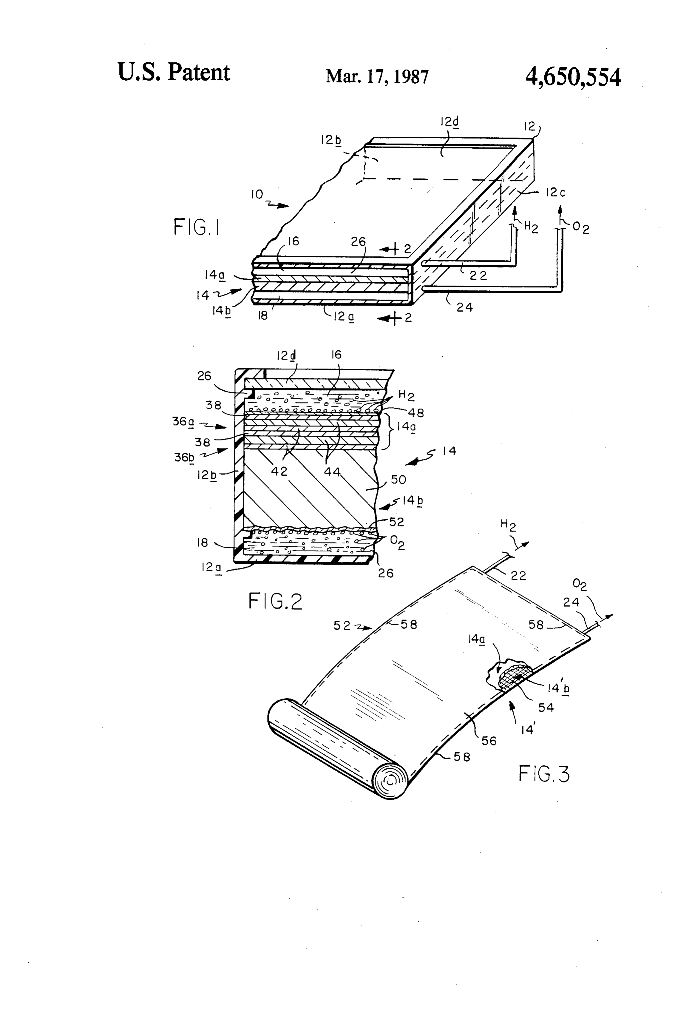
For a fuller understanding of the nature and objects in excess of 1.5 volts. Various other materials for thin of the invention, reference should be should be made to film tandem solar cells are known, including hydroge the following detailed description taken in connection 5 nated amorphous silicon alloys with germanium, car with the accompanying drawing, in which: bon, nitrogen, and fluorine. FIG. 1 is a fragmentary sectional view of photoelec Each photovoltaic cell 36a and 36b includes an n trolysis apparatus incorporating my invention; doped layer 38 which faces the hydrogen evolving FIG. 2 is a fragmentary sectional view on a much surface of the cell 14, i.e., upwards in FIG. 2, and a larger scale taken along line 2-2 of FIG. 1; and 10 p-doped layer 42 which faces toward the oxygen evolv FIG. 3 is an isometric view on a small scale, with ing cell 14 surface, i.e., downwards in FIG. 2. As noted parts broken away, illustrating another embodiment of above, the cells 36a and 36b are of the amorphous sili the invention. con type. Therefore, each includes a non-doped layer 44
Detailed description of the
between the doped layers 38 and 42 in order to increase 15 the efficiency of the cell. If these cells were composed
PREFERRED EMBODIMENTS of crystaline silicon, the non-doped layer 44 could be Referring to FIG. 1 of the drawing, photoelectrolysis omitted without any appreciable loss of efficiency. apparatus made in accordance with this invention is It should be mentioned at this point, that conven indicated generally at 10. It includes a box-like housing tional thin film photovoltaic or solar cells include a 12 having a bottom wall 12a, a pair of side walls 12b, a 20 solid layer of a transparent, electrically conductive pair of end walls 12c, and a top wall 12d, at least the last material such as fluorine-doped tin oxide or tin-doped being substantially transparent to sunlight. The housing indium oxide on the face of the cell that is illuminated 12 may have any selected length and width. For exam by the sun in order to conduct the electrical charges ple, it may have the dimensions of a conventional solar produced by the cell transversely to a wire leading from panel. 25 the cell. Such layers are not required in the cells 36a and Positioned inside housing 12 is a photoelectrolysis 36b of apparatus 10 because their function is performed cell shown generally at 14. This cell is in the form of a by the aqueous electrolyte 26. Moreover, any such tin flat slab or panel which is supported horizontally inside oxide or indium oxide layer at the exposed surface of housing 12 midway along the housing height or thick cell 36a would be disolved rapidly in the electrolyte ness so as to define a housing compartment or chamber 30 during hydrogen evolution. The fact that such conduc 16 located above the cell and a housing compartment or tors are not required at the surfaces of cells 36a and 36b chamber 18 located between the cell and the housing simplifies the manufacture of those cells and thus re botton wall 12a. As best seen in FIG. 1, a first fluid duces the overall cost of the present apparatus. Prefera conduit 22 extends through a housing end wall 12c to bly, however, a very thin, transparent platinum film 48 compartment 16 and a second similar conduit 24 leads 35 is deposited on the exposed surface of the photovoltaic through housing end wall 12c to compartment 18. section 14a not as a transverse conductor, In use, housing 12 is filled with an aqueous electrolyte R16-002 but to function as a catalyst to encourage the 26 such as sulfuric acid. This liquid may be introduced evolution of hydrogen gas at that surface. The platinum into the housing, for example, through conduits 22 and film also protects the silicon surface from oxidation by 24 or openings in the housing walls. When cell 14 is the electrolyte. The apparatus will operate without that immersed in that electrolyte and illuminated, hydrogen film, but at a reduced efficiency and lifetime. evolves at the surface of cell 14 in compartment 16 as It is important to note that since the electrolyte 26 indicated by the small bubbles H2 in FIG. 2. This gas serves as the photocells' charge conductor as just dis accumulates in compartment 16 and is conducted there cussed, section 14a should be porous so that electrolyte from by conduit 22 leading upward to prevent the elec 45 penetrates across the cells 36a and 36b over substan trolyte from draining from the housing. At the same tially their entire common areas. If section 14a were not time, oxygen gas evolves at the undersurface of cell 14 porous, the electrical circuit through the electrolyte in housing compartment 18 as indicated by the small would have to be provided less desirably by conduction bubbles O2 present at that location. The oxygen accu extending around the edges of section 14a. mulating in compartment 18 finds its way to conduit 24 50 Still referring to FIG. 2, the barrier section 14b of the and is conducted upward from the housing. Preferably, electrolysis cell 14 is composed of a solid, but porous, apparatus 10 is tilted somewhat to elevate the conduit electrically conductive material 50 such as a valve metal containing end of the housing so that the evolved gases or metallic compound. When section 14b is immersed in tend to collect there to facilitate their removal from the the electrolyte 26, the electrolyte fills those pores. It housing. 55 should be mentioned that porous conductive electrodes, Refer now to FIG. 2 of the drawing which shows the including those made of valve metals, have been used construction of the electrolysis cell 14 in greater detail. before in connection with electrolysis, European appli As seen there, the cell section 14a is composed of one or cation EP No. 0013572 discloses an electrolytic cell more photovoltaic or solar cells, the illustrated appara incorporating such a porous electrode for oxygen ioni tus having two such cells shown generally at 36a and zation. The electrode is impregnated with an oxygen 36b, The number of solar cells is such that the total evolution catalyst, e.g. platinum, and immersed in an voltage generated by the cells is sufficient to electrolyze aqueous electrolyte. The presence of the pores greatly water. The theoretical minimum voltage required to do increases the catalytic surface area of the electrode this is about 1.23 volts, but in actual practice, a voltage wetted by the electrolyte at which electrolytic action of about 1.5 to 2 volts is required for the generation of 65 occurs, thus maximizing the ionization of oxygen. In hydrogen with a normal solar input. Thus, the cells 36a other words, current flow between electrode and elec and 36b may comprise, for example, two conventional, trolyte and the electrochemical reaction occur through thin, amorphous silicon solar cells bonded together one out the electrode. In applicant's cell, on the other hand, 5 the porous barrier section 14b does not allow, at least at osmium, palladium, rhodium, and ruthenium. Platinum the small operating voltage of the cell 14, any electric is generally prefered in acid electrolytes, although irid current flow to the electrolyte solution within its pores. ium is more durable. In alkaline electrolytes, base metals In the illustrated cell, this is because the selected barrier such as nickel, cobalt, and iron, may be used as hydro section material has a high over potential for oxygen. In gen evolution catalysts.
another embodiment, it is because the pore surfaces or For aqueous electrolytes 26, non-oxidizing acids are walls are provided with an insulating coating, e.g., by preferred, such as sulfuric acid (H2SO4) and perchloric oxidation. In either event, no decomposition of the acid (HC1O4). Alkaline electrolytes, such as potasium electrolyte ocurs within the barrier section 14b. Thus, hydroxide (KOH) solutions, allow the use of less expen that section functions as a membrane more or less. On O sive catalysts, but alkaline electrolytes tend to degrade the other hand, the lower surface of section 14b facing silicon-based photovoltaic layers. Salt electrolytes, such housing compartment 18 carries a coating 52 of an oxy as sodium sulphate (Na2SO4) are the least prefered elec gen evolution catalyst such as ruthenium oxide (RuO2) trolytes, since they require the expensive noble-metal which has a low over-potential for oxygen in an electro catalysts; they also tend to slowly degrade the quality of lytic cell. Resultantly, oxygen gas is evolved only at the 15 the photovoltaic materials.
lower catalytic surface of section 14b and not within the As noted previously, the catalytic coating or film 48 section itself. Furthermore, during the operation of on the upper surface of the photovoltaic section 14a apparatus 10, the small size of the barrier section pores must be transparent to sunlight. To permit wide flexibil and surface tension prevent the oxygen gas generated at ity in the selection of that catalyst, it may be desirable to the under surface of section 14b from percolating up 20 reverse the surfaces of the electrolysis cell 14 that pro through cell 14 into the housing compartment 16 and duce the hydrogen and oxygen gases. In other words, it mixing with the hydrogen gas accumulating therein. may be desirable in some cases to apply the oxygen Therefore, the volumes of hydrogen and oxygen gases evolution catalyst to the upper, illuminated surface of produced by the apparatus are kept completely isolated cell 14 and the hydrogen evolution catalyst to the within the housing 12. 25 lower, dark surface thereof. In that event, the order of The electronic conductivity of the solid metallic the layers in the photovoltaic cells 36a and 36b would structure of section 14b is necessary to transmit the be reversed so that the n-type (negative) layers face electric current generated by the photovoltaic section downward toward section 14b and the p-type (positive) 14a all the way to the coated lower surface of section layers face upward toward the housing compartment 14b. The use of such a conductive membrane in appara 30 16.
tus 10 is in sharp contrast to conventional electrolysis FIG. 3 shows an apparatus embodiment 52 in the cells which employ only insulating solids such as asbes form of a flexible mat which can be transported and tos cloth to form the structure between the cell elec stored in a space-saving, rolled-up condition and un trodes. rolled on the ground or other horizontal surface when Suitable valve metals for the construction of the elec 35 in use. Apparatus 52 is similar to apparatus 10 described trically conductive barrier section 14b include titanium, above both structurally and operationally and accord zirconium, vanadium, hafnium, niobium, tantalum, ingly carries many of the same identifying numerals. It tungsten and their alloys. The metals can be in the form differs in that its barrier section 14b includes a nitride of sintered porous plates or closely woven wire cloth. coated fiberglass cloth sheet 54 instead of the porous Metals in these forms are commonly available as filters. rigid plate comprising apparatus 10. The photovoltaic Suitable metallic compounds of the valve metals include section 14a described above is bonded to the upper nitrides, carbides, and borides of the valve metals, such surface of sheet 54 and the undersurface of sheet 54 as titanium nitride (TiN), titanium carbide (TiC), and carries an oxygen-evolving catalyst coating 52 similar titanium boride (Tib2). Also suitable is electrically con to the one in the apparatus 10 to form an electrolysis cell ductive titanium oxide which has been reduced (Ti 45 shown generally at 14. Cell 14 is placed between the O2-x) and/or doped with elements such as niobium, plies of a lengthwise-folded, light transmitting plastic tantalum, tungsten, or fluorine, to increase its electrical film or sheet 56. Then the free edges of those plies are conductivity. These materials can be produced in the sealed together at opposite faces of the cell edges as form of porous ceramic plates using well known pro shown at 58 to form a fluid-tight, light transmitting cesses. Although these metallic compounds are not 50 bag-like enclosure for the cell 14, with the cell dividing available in the form of fibers or wires, they may be the enclosure into upper and lower compartments. A vapor-deposited on the surfaces of fibers to form an conduit 22 connects to the upper compartment in appa electrically conductive porous structure suitable for use ratus 52 while conduit 24 leads from the lower compart as cell section 14b as will be described later in connec ment thereof. When the apparatus is deployed on the tion with FIG. 3. 55 ground with its photovoltaic layer 14a facing the sun, While ruthenium oxide (RuO2) is the prefered coat hydrogen gas issues from conduit 22 and oxygen gas ing 52 catalyst for evolving oxygen at the lower surface flows from conduit 24. As noted above, this apparatus of section 14b, that material may be combined with embodiment is advantaged because it can be rolled up cocatalysts such as rhodium oxide (RhC2), iridium into a compact package when being transported or oxide (IrO2) and/or manganese oxide (MnO2) and with when not in use. Also, it is very easy to deploy on any binding agents such as titanium oxide (TiO2), zirconium more or less horizontal surface, even when the appara oxide (ZrO2) ortantalum oxide (Ta2O5). These catalysts tus has a very large working area.
are known in the art and their preparations and proper The invention is illustrated by the following specific ties are described in detail in U.S. Pat. Nos. 3,632,498; examples:
3,711,385; 3,616,445 and 3,948,751, among others. 65
Example 1
Hydrogen promoting catalysts for the light transpar ent coating 28 at the upper surface of the photovoltaic A sintered ceramic plate of titanium nitride for use as section 14a include, in addition to platinum, iridium, section 14b was first coated with an oxygen-evolution 6 catalyst by dissolving hydrated ruthenium trichloride in the apparatus results in the generation of the hydrogen dilute (4:1) hydrochloric acid, and then evaporating the and oxygen gases at completely separate locations in the solution almost to dryness. The residue, constituting a apparatus, with the barrier section preventing recombi more or less soluble form of ruthenium chloride, was nation of those gases. Therefore, the apparatus pro mixed with a small amount of isopropanol and a small 5 duces efficiently two separate, substantially pure hydro amount of polyvinyl alcohol was added as a thickening gen and oxygen gas streams.
agent to prevent the catalyst from soaking into the It can thus be seen that the objects set forth above, ceramic plate. This mixture was then painted onto one among those made apparent from the preceding de surface of the ceramic plate. The layer was then dried in scription, are efficiently attained. Also, it should be an oven at 50 C., and then fired in air in an oven main 10 understood that certain changes may be made carrying tained at 400° C. to form the coating 52. out the above method and in the construction set forth The other (upper) surface of the titanium nitride plate without departing from the scope of the invention. For was sanded lightly to remove any oxides or other con example, the same technique and apparatus may be used tamination. Then it was dusted lightly with magnesium for the decomposition of other liquid electolytes by oxide powder, which, at a later step in the formation 15 proper selection of the evolution catalysts applied to the process, produced the required pore structure in the upper and lower surfaces of the electrolysis cell 14. For photovoltaic section 14a to be formed on the plate. example a hydrogen bromide (HBr) or hydrogen chlo Next, a conventional glow discharge apparatus was ride (HCl) electrolyte may be decomposed using the used to deposit hydrogenated amorphous silicon layers same gas evolution catalysts described above on the on the magnesium oxide-coated surface of the plate in 20 upper and lower surfaces the following sequence to form the two cells 36a and hydrogen and bromine gasesoforthe cell 14 to generate hydrogen and chlorine.
36b of the photovoltaic section 14a: Therefore, it is intended that all matter described herein 1. boron-doped layer, 200A thick and illustrated in the drawing shall be interpreted as 2. non-doped layer, 4000 A thick 25 illustrative and not in a limiting sense. 3. phosporous-doped layer, 100 A thick What is claimed as new and desired to be secured by 4, boron-doped layer, 100A thick Letters Patent of the United States is: 5. non-doped layer, 1500 A thick. 1. A photoelectrolysis method for decomposing a 6. phosphorous-doped layer, 100 A thick liquid electrolyte into a plurality of decomposition Finally, a platinum film about 10 A thick was depos products, said method comprising the steps of
The plate, coated thusly, was next placed in a 1 nor A. forming a porous layer of an electronically con mal sulfuric acid solution. The acid dissolved the mag ductive material having a relatively high over nesium oxide powder particles, thereby opening up potential for said decomposition products in an pores through the tandem photovoltaic cell section to electrolytic cell;
permit aqueous electrolyte to penetrate through that 35 B. laminating a sheet-like porous photovoltaic unit section, thereby completing the electrolysis cell. having a total output voltage sufficient to electro When that cell was wetted with sulfuric acid and lyze said electrolyte on one surface of said layer so placed in sunlight so that the light was incident on the that the two are connected together both mechani platinum-coated surface of the cell, hydrogen bubbled cally and electrically as a panel; from that surface and oxygen bubbled from the oppo 40 C. coating the opposite surface of said layer with a site, ruthenium oxide-coated surface. catalyst having a relatively low overpotential for EXAMPLE 2 one of said decomposition products in an electro lytic cell;
A section of fiberglass cloth was coated with titanium D. immersing said panel in said liquid electrolyte; and nitride by chemical reaction from the vapor phase. 45 E. illuminating said photovoltaic unit with light en Then the steps of Example 1 were repeated with the ergy whereby said one of said decomposition prod coated cloth substituting for the titanium nitride ce ucts evolves at the coated surface of said layer and ramic plate in that example. Next, coextensive sheets of another decomposition product evolves at the illu transparent plastic film were placed against the upper minated surface of said photovoltaic unit, with the and lower surfaces of that cell and secured together 50 panel being a barrier that isolates said evolving around their edges to form a lightweight, flexible, mat products from one another. like structure. When that structure was spread out on a 2. The method defined in claim 1 and including the flat surface in sunlight and filled with sulfuric acid, additional step of applying hydrogen gas evolved at the upper surface of the cell said photovoltaic unit a thintotransparent the illuminated surface of coat of a mate and oxygen gas was produced at the lower surface rial that catalyzes said another decomposition product.
thereof.
It will be seen from the foregoing that my photoelec 3. The method defined in claim 1 and including the trolysis apparatus is quite effective for providing hydro additional steps of
A. encapsulating said panel and electrolyte in an gen and/or oxygen gases from water and sunlight. The apparatus is quite compact and may even be made as a enclosure so that the panel divides the enclosure flexible mat. Further, the apparatus is a unitary struc into two compartments, and ture that does not require any external circuitry whatso B. conducting a said decomposition product from at ever in order to operate properly. Nor does the photo least one of said compartments. voltaic section of the apparatus require a coextensive 4. Integrated photoelectrolysis apparatus for catalyz transparent conductor of the type found on conven 65 ing the photodecomposition of water into separate gas tional solar cells. Therefore, it is not subject to failure streams of hydrogen and oxygen, comprising: due to a pinhole or other small defect in its light-absorb A. a porous electronically conductive barrier section ing semiconductor layers. Finally, the barrier section of having opposite surfaces;
Page 7scan →
B. a plural layer photovoltaic section bonded me B. means for conducting fluid out of said first cham chanically and electrically to one surface of said ber;
barrier section; C. means for conducting fluid out of said second C. a catalyst on the opposite surface of said barrier chamber; and section to promote the electrolytic evolution of one D. means defining a light-transmitting area in the wall of said hydrogen and oxygen gases; of said container opposite said photovoltaic sec D. an aqueous electrolyte permeating said barrier tion.
section; and 17. The apparatus defined in claim 16 wherein said E. inhibiting means in said barrier section for inhibit 10 sections ratus can and said container are flexible so that the appa be rolled up into a compact package.
ing the evolution and presence of said gases in the 18. The apparatus defined in claim 17 wherein said pores of said barrier section when said photovol barrier section comprises taic section is exposed to light, A. a sheet of fiberglass cloth; and whereby said one of said gases evolves only at said B. a material selected from the group consisting of a opposite catalytic surface of said barrier section 15 valve metal and a nitride, carbide and boride of a ,and valve metal coated on said cloth. the other of said gases evolves only at the surface of 19. Photoelectrolysis apparatus for decomposing a said photovoltaic section. liquid electrolyte into a plurality of separate streams of 5. The apparatus defined in claim 4 wherein said decomposition products comprising inhibiting means comprise insulating means on the Sur 20 A. a generally fluid-tight enclosure; faces of said barrier section pores for electrica11y insu B. a sheet-like, porous, electronically conductive lating said barrier section from said electrolyte. barrier layer having opposite surfaces; 6. The apparatus defined in claim 4 wherein said C. a sheet-like, porous, plural-layer photovoltaic sec inhibiting means comprise means for providing a higher tion bonded mechanically and electrically to one over-potential for the evolution of said one of said gases 25 surface of said barrier layer; at the interior surfaces of said barrier section pores than D. a catalyst coating on the opposite surface of said at said opposite catalytic surface of the barrier section. barrier layer to promote the electrolytic evolution 7. The apparatus defined in claim 4 wherein said of one of said products at said opposite surface, said photovoltaic section is also porous and permeated with layer, section and coating forming a unitary lami said electrolyte. 30 nated panel;
8. The apparatus defined in claim 4 wherein: E. means for mounting said panel in said enclosure so A. said one of said gases is oxygen; and as to divide said enclosure into a first chamber B. said catalyst comprises ruthenium oxide. contiguous to said photovoltaic section and a sec 9. The apparatus defined in claim 4 wherein: ond chamber contiguous to said opposite coated A. said one of said gases is hydrogen; and 35 surface of said barrier layer; B. said catalyst is selected from the group consisting F. means for introducing a liquid electrolyte into said of platinum, palladium, iridium, osmium, rhodium, enclosure so that it permeates said layer and sec ruthenium, and their alloys. tion;
10. The apparatus defined in claim 4 and further in G. means for preventing current flow from said bar cluding a transparent catalyst coating on the exposed rier layer to the electrolyte in the pores of said surface of said photovoltaic layer to promote the elec barrier layer; and trolytic evolution of the other of said gases. H. means for exposing said photovoltaic section to 11. The apparatus defined in claim 10 wherein: light whereby
A. said one of said gases is oxygen; and A. said one of said products evolves only in said sec B. said transparent catalyst coating is selected from 45 ond chamber, and the group consisting of platinum, iridium, osmium, the other of said products evolves only in said first palladium, rhodium, ruthenium and their alloys. chamber; and
I. conduit means attached to said enclosure for con 12. The apparatus defined in claim 10 wherein: ducting fluid from at least one of said chambers. A. said one of said gases is hydrogen; and 50 20. The apparatus defined in claim 19 wherein said B. said transparent catalyst coating comprises ruthe preventing means comprise insulating means on the nium oxide.
surfaces of said barrier section pores for electrically 13. The apparatus defined in claim 4 wherein said barrier section comprises a material selected from the insulating said barrier section from said electrolyte. 21. The apparatus defined in claim 19 wherein said group consisting of a valve metal and a nitride, carbide 55 preventing means comprise means for providing a and boride of a valve metal. higher over-potential for the evolution of said one of 14. The apparatus defined in claim 13 wherein said said products at the surfaces of said barrier layer pores barrier section comprises titanium nitride. than at said opposite coated surface of the barrier layer. 15. The apparatus defined in claim 14 wherein said 22. The apparatus defined in claim 19 wherein said electrolyte comprises sulfuric acid or perchloric acid. laminated structure and enclosure are flexible. 16. The apparatus defined in claim 4 and further in 23. The apparatus defined in claim 19 and further cluding: including a second catalyst coating on the exposed sur A. a fluid-tight walled container for said sections, said face of said photovoltaic section, said second coating container walls and said sections defining being a first chamber in said container adjacent said pho 65 A. transparent, and tovoltaic section, and B. promoting the evolution of said another decompo a second chamber in said container adjacent saidi sition product.
barrier section;
Provenance
- Collection
- Patents citing this work
- Pages
- 7
- Method
- pdftotext (the PDF's own text layer) + pdftoppm 300dpi page scans
- Patent office record
- patents.google.com →
- Source
- Google Patents citing-documents table
- Assignee
- Gordon Roy Gerald
- Published
- 1987-03-17
- Transcribed from
- patentimages.storage.googleapis.com →