

patent · US4659305A
Flue gas recirculation system for fire tube boilers and burner therefor
21 April 1987
Text
Page 1bibliographic recordscan →
United States Patent (19)
Nelson et al.
(54) FLUE GAS RECIRCULATION SYSTEM FOR
FRETUBE BOLERS AND BURNER
THEREFOR
Inventors: Peter K. Nelson, Palmyra, Pa.; Elroy M. Rulseh, Milwaukee, Wis.
(73) Assignee: Aqua-Chemi, Inc., Milwaukee, Wis.
51 Int. Cl." ............................................... F23M, 3/00 52 U.S. C. ......................................... 431/9; 431/115 Field of Search ............................ 431/9, 115, 116
4,483,832 11/1984 Schirmer ............................. 431/16
Primary Examiner-Carroll B. Dority, Jr.
Attorney, Agent, or Firm-John C. Cooper, III; Fred Wiviott
A flue gas recirculation system for fire tube boilers includes a duct connected to the boiler gas discharge stack and to a fan. Another duct couples the fan to a specially designed burner in the boiler. Recirculated flue gas is injected downstream of the fuel/air mixture in the burner and cools the flame leading to substan tially reduce the NO content in the boiler stack emis sions. The burner includes conventional damper and air diffuser systems and a plurality of openings near the inner end of the burner housing, through which the boiler fuel is admitted and mixed with the air. A plural ity of slots are formed at the outlet end of the burner, the slots being coupled to an annular chamber surround ing the burner. The duct from the recirculation fan is coupled to such annular chamber. Recirculation of be tween about fifteen to twenty percent of the flue gas in the above-described device can result in NOx reduc tions of more than sixty percent, when compared to a similar boiler operating without such flue gas recircula tion.
11 Claims, 5 Drawing Figures
Drawings
Page 2drawing sheetscan →
Page 3drawing sheetscan →
Page 4scan →
Flue gas recirculation system for fire
through the constricted area of the fire tubes. For exam
Tube bolers and burner therefor
ple, with fire tube boilers, pressure losses of 15 inches or more are common, while with water tube boilers, the
Background of the invention
pressure drops encountered are typically 8 inches or 5 less. Greater recirculation rates are required for firetube 1. Field of the Invention boilers in comparison to watertube boilers to obtain the The present invention relates generally to the art of same percentages of NOx reduction. This results be fire tube boilers and more particularly to a fire tube cause the combustion chamber for the firetube boiler is boiler system which includes a specially designed 10 a narrow tube compared to the large volume chamber burner and a duct and fan system for recirculating a of the watertube boiler. This results in shorter residence minor portion of the flue gas to the burner. Still more time for the flue gases in firetube furnaces. specifically, the present invention relates to a fire tube Several patents are known to the present inventors boiler having substantially reduced NOx emissions. which relate generally to the subject offlue gas recircu 2. Description of the Prior Art lation. In Leahy's U.S. Pat. No. 964,031, issued July 12, The concept of flue gas recirculation to reduce NO 15 1910 for "Liquid Hydrocarbon Burning Apparatus,” a emissions has been known for many years, but to the fire tube boiler is described, in which a portion of the knowledge of the present inventors, this concept has combustion gas is directed from the exit of the combus only been successfully applied to NO pollution control tion tubes to the burner area. Control of the amount of in water tube boilers. In such prior art flue gas recircula recirculated gas is provided by a damper at the exhaust tion systems, a duct is typically connected to the flue 20 stack, by a pair of dampers at the inlet side of the burner stack and to a small recirculation fan. Another duct is (to control injection through a plurality of orifices coupled to the fan and to the combustion air inlet of the spaced along the combustion housing, and by control of burner of the boiler. Only in recent years has the tech the space which exists between the burner and the com nology been employed with packaged boilers, mainly because of changes in state and local emission limits, 25 bustion housing). Leahy relates specifically to the burn ing of fuel oils and the recirculation of partially con principally in the State of California. sumed combustion products to increase the efficiency of Depending on the type of fuel which is being burned, combustion.
two types of nitrogen oxides can be formed. Fuel bound reduction of This patent does not teach or suggest the NOx is formed as a result of nitrogen being present in tages thereofNOx in by flue gas recirculation, the advan reducing thermal NOx formation, the the fuel itself, e.g., in fuel oils. During combustion, the 30 nitrogen is released and quickly reacts with the oxygen combustion device of the present invention, or any of in the combustion air to form NO. The reactions to the specific apparatus or controls used therewith. More produce fuel bound NOx are not particularly tempera over, since modern package boilers typically have ex ture-dependent. Thermal NOx is formed, on the other tremely high combustion efficiencies, one skilled in the hand, when high combustion temperatures break down 35 art would not look to Leahy as a patent of interest for the nitrogen gas in the combustion supporting air to NO reduction.
atomic nitrogen. When this occurs, the atomic nitrogen In Engels' U.S. Pat. No. 2,110,209 issued Mar. 8, 1938 will very quickly react with oxygen to form thermal for "Furnace,' the invention relates to protection of the NO. costly combustion chamber by providing a blanket of If natural gas is employed as the boiler fuel, only cooler gas, for example recirculated flue gas, along the thermal NOx is formed, because clean natural gas does wall of the combustion chamber by injecting a flow of not contain any nitrogen containing compounds. On the such cooler gas through a plurality of openings at the other hand, both thermal and fuel bound NO are formed inlet to the chamber. The patent does not teach or sug when burning fuel oils. Moreover, the amount of fuel gest the use of recirculated flue gas to reduce NO bound NO production in fuel oil combustion will de 45 levels or the specific burner configuration of the present pend on the quality of the oil. No. 6 oil, for example, invention or the control systems used therewith. An will produce a considerably greater amount of fuel external duct and a special fan are provided for the bound NO than will No. 2 oil, because the former injection and proper mixing of the recirculated flue gas, contains a greater quantity of fuel bound nitrogen. which in turn, reduces NO production. It is also generally known that by cooling the com 50 Another system which employs recirculated flue gas bustion flame temperature, NOx production can be de is that described in Keller's U.S. Pat. No. 2,174,663 creased. From the foregoing description, it is apparent issued Oct. 3, 1939 for "Tubular Gas Heater.' This that the effect of flame temperature reduction will be system includes heat exchanger tubes which are tra greatest when thermal NO production is involved and versed by gases to be heated, and in which preheated air will be less effective in reducing fuel bound NO pro 55 is used for combustion. To prevent unduly high heating duction. It follows then that flame temperature reduc of the heat exchanger tubes, flue gases are recirculated tion by the recirculation of stack gas is most effective in two paths, one flowing along those heat exchanger when the boiler is burning natural gas. tubes in which adjoin the furnace wall, and another While NOx reduction in water tube package boilers flow path which is introduced directly above the flame has been successfully accomplished prior to the present (the combustion chamber being oriented vertically). invention, optimization of flue gas recirculation for fire Apertures are provided to control the amount of recir tube boilers has been difficult. The technical problems culated gas passing in the two flow paths, the apertures with the two kinds of boilers result from the differences being provided in a partition surrounding the combus in the amount of combustion air which must be injected, tion chamber. As previously mentioned, the patent re and differences in pressure drops at various locations in 65 lates to prevention of undue heating of heat exchange the systems. Much higher combustion air injection pres tubes, rather than NOx reduction, and the combustion sures are required with fire tube boilers because the device of the present invention and the controls used combustion gases flowing through the boiler must pass therewith are not disclosed or suggested in this patent.
Page 5scan →
Recirculated combustion gases are also utilized in which can be incorporated into new boilers or can be Campbell's U.S. Pat. No. 2,430,101 issued Nov. 4, 1947 added to existing units.
for "Combustion Chamber.' The device described here A further object of the present invention is to provide a burner is used in the baking industry. Recirculated exhaust cooling recirculated for fire tube boilers which is designed to inject gases are passed from an external duct into a casing flue gas at the outlet of the burner. surrounding the combustion chamber to reduce its tem vide control systems of
A different object the present invention is to pro for the flue gas recirculation sys perature and to pick up heat therefrom. The recircu lated gas then combines with the combustion gas at the tem which will cooperate with convention boiler air outlet of the combustion chamber and flows through a O and fuel controls to optimize the efficiency of the flue radiator system used to warm the baking space. The gas recirculation NOx reduction system of the present patent does not suggest the case of recirculated flue gas invention.A still further object of the present invention is to for NOx reduction or the round combustion apparatus provide a NOx reduction system which will allow boiler of the present invention.
Bailey discloses another recirculation system in his installations emission to meet increasingly stringent air quality limitations.
U.S. Pat. No. 3,741,166 issued June 26, 1973 for "Blue 15
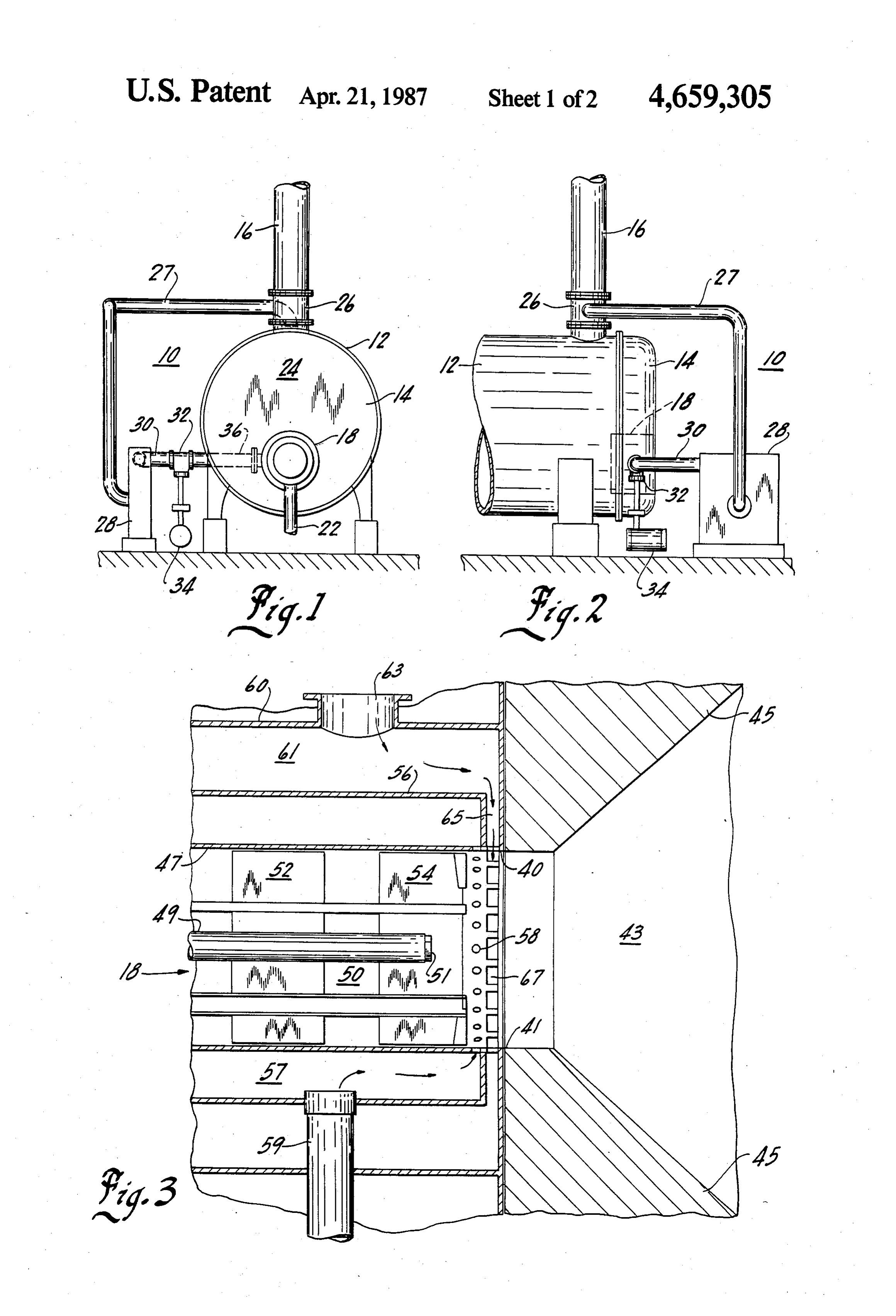
Flame Retention Gun Burners and Heat Exchanger accomplished How these and other objects of the invention are Systems.” In this system, a low pressure area is created will be described in the following de by the vigorous injection of a major portion of the tailed description of the preferred embodiment, taken in combustion supporting air through a vitiation zone 20 conjunction with the drawings. Generally, however, positioned upstream of the fuel injection region. The they are accomplished by providing an outlet duct from low pressure area causes a portion of the combustion the stack of a fire tube boiler, through which flue gases gases to be recirculated to chemically alter the combus can be recirculated. The fan inlet is coupled to this duct tion air before it encounters the fuel spray. The gases and the fan outlet is coupled to a second duct which is are cooled to below 800 F. before entering the vitiation connect are to the burner assembly of the boiler. Controls provided so that an appropriate percentage of the zone. The remainder of the combustion air is injected 25 through a plurality of diverging jets aimed toward the flue gas will be recirculated. The preferred system in combustion chamber and is used to cool the fuel nozzle. cludes standard control systems for regulating the fuel The patent indicates that the system reduces localized and combustion air delivered to the boiler, and diffusers ... hot spots which augment NOx production. This patent for imparting the desired flow to the incoming combus does not disclose the recirculation offlue gas or the use 30 tion air. Inlets for the recirculated flue gas comprise of the novel combustion apparatus of the present inven slots located in the forward end of the burner assembly, tion. the slots being coupled to an annular chamber surround In commonly-assigned U.S. Pat. No. 4,519,773 issued ing the burner. Such chamber is also coupled to the on May 28, 1985 to Mark G. Parish, et al. for "Dual ously second flue gas recirculation duct which has been previ Cannister Gas Housing,” a combustion apparatus is 35 mentioned. Using the system of the present inven disclosed which may be employed for the introduction tion, it has been found that large quantities of recircu lated flue gas can be accomplished with small fan re of two different fuel gases into a combustion chamber, quirements and large reductions in NO. Other ways in the fuel gases having different fuel values. For example, which the objects of the invention are accomplished the disclosed dual cannister housing could be used with natural gas, land fill gas, etc. Depending on the quanti will become apparent to those skilled in the art after the ties and/or costs of the respective gases at any particu present specifications have been read and understood. lar time, the gases can be supplied one at a time or mixed DESCRIPTION OF THE DRAWINGS in the device of this patent to provide economical and FIG. 1 is a schematic end view of a boiler and a flue efficient combustion. The aforementioned patent does 45 gas recirculation system according to the preferred not disclose flue gas recirculation, and in fact, teaches away from using a dual cannister concept for flue gas embodiment of the present invention; recirculation since both gases used in the patent have gasFIG. 2 is a schematic side view of the boiler and flue recirculation system shown in FIG. 1;
significant fuel values. As previously mentioned, mod FIG. 3 is a cross-sectional side view of the burner ern boiler technology has led to efficiency improvement assembly employed in the preferred embodiment of the to the point that there is little, if any, fuel value in the 50 exhaust gases. This is especially true for those modern present invention;
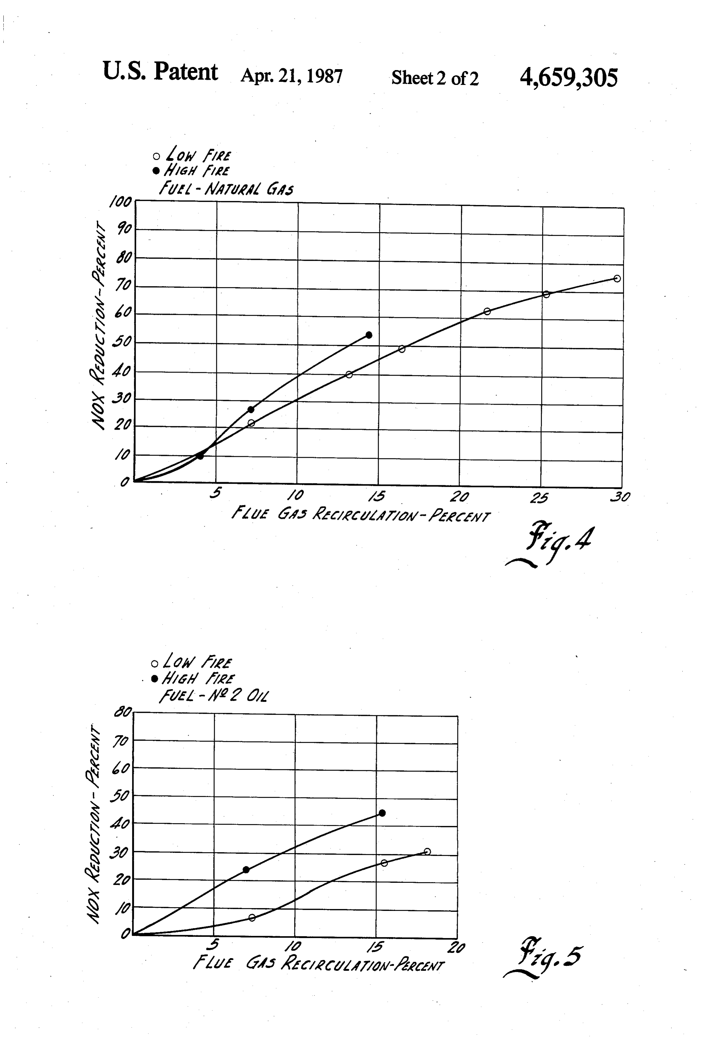
boiler designs which include control systems for regu theFIG. 4 is a graph showing the NOx reduction using apparatus of the preferred embodiment of the pres lating fuel and air supply during start-up and operation under varying conditions. ent invention, with natural gas as the fuel and showing An improved flue gas recirculation system for fire 55 both high and low boiler fire conditions; and tube boilers which would provide substantial NOx re theFIG. 5 is a graph showing the NOx reduction using apparatus of the preferred embodiment of the pres duction and which could be employed with new boilers or be added to existing boilers, would represent a sub ent invention. Using No. 2 oil as the fuel and showing stantial advance in the art. both high and low boiler fire conditions. In the various drawings, like reference numberals are
OBJECTS AND SUMMARY OF THE used to illustrate like components.
Invention
It is a primary object of the present invention to pro
Detailed description of the
Preferred embodiment
vide a flue gas recirculation system for fire tube boilers which includes a novel burner and which leads to sub 65 Ashcematic illustration of the system according to stantial NO reduction. the preferred embodiment of the present invention is Another object of the present invention to provide a shown in FIGS. 1 and 2. Before proceeding to the de NOx reduction system and novel burner arrangement scription of those Figures, it should be explained that 6 the particular type shape of boiler is not critical to the (not shown) of the boiler, valve 32 can be used to con present invention, and that numerous conventional de trol the flow of recirculated flue gas at a given percent vices commonly employed with regular or packaged age throughout the firing range of the boiler after start boilers are not shown (so that the feature of the present up and a warming period have been achieved. invention can be better appreciated). For example, the Several safety features which are not directly related air injection fan, trim systems for controlling air and to the present invention should be mentioned here, even fuel ratios and pressures, sensors for determining boiler though they have been designed into the commercial operating conditions, ignitors, etc., are not shown, but embodiment of our assignee's system. First, the flue gas they would be used in a boiler installation employing recirculation system is not allowed to operate until the the principles of the present invention. 10 boiler warms up to a predetermined temperature and A fire tube boiler flue gas recirculation system 10 is reaches operating status. The system to accomplish this shown in FIGS. 1 and 2 to include a generally cylindri result is similar to those conventional systems used for cal boiler 12 having a generally circular end wall 14. A low fire hold control, where boiler water temperatures stack 16 is provided at the top of boiler 12 for the com will determine proper operating conditions. This fea bustion exhaust. In the illustrated embodiment, a burner 15 ture will prevent a potentially dangerous condition 18 is provided in end wall 14 and fuel supply pipe 22 is which would occur if excessively high recirculation shown coupled thereto at FIG. 1. It should also be ratios were employed in a cold boiler.
appreciated that an air fan will be located in the vicinity Another safety feature provided in the commercial of the numerical 24 and that suitable duct work and embodiment is a differential pressure switch installed controls (not shown) will connect the fan to burner 18. 20 across the fan to insure that the fan 28 is operating prop A first duct 27 (which may be insulated) is coupled to erly. This feature prevents hot gases from the boiler a vent stub adapter 26. The adapter 26 is provided to from reversing through the fan and insures that the fan take advantage of the flue gas velocities traveling up is actually creating flow in the proper direction. If, for wardly in stack 16. Such velocities will be used in sys any reason, the pressure differential required by the tem 10 to minimize inlet pressure drops in the inlet to 25 switch is not met, the control valve 32 will shut tight duct 27, thereby minimizing the required static pres and an alarm will sound after the flue gas recirculation sure. The other end of duct 27 is coupled to the inlet of system has been deactivated.
a recirculation fan 28 which may be selected from any Finally, the aforementioned signal obtained from the number of known fans, but which must be sized prop boiler jackshaft is compared to the actual position of the erly for the particular flue gas recirculation job to be 30 control valve 32 by a comparator means. If, for any accomplished. reason, these two valves do not match within certain The sizing of the fan 28 will involve three major limits, improper recirculation is occuring and the flue factors. The first is the percentage of flue gas to be gas recirculation system will be shut down, thus pre recirculated, which in turn determines the quantity of venting the potentially serious problem of high levels of gas which needs to be moved. The percentage affects 35 recirculated gas. Such high levels can, of course, cause not only the quantity (i.e., CFM), but also the static flame instability and/or loss of the flame. pressure. Ihe more recirculated flue gas required, the Located downstream of the valve 32 is another duct greater the static pressure requirement also. 36 leading to burner 18. Housing 18 will now be de The second factor which will affect the size of fan 28 scribed in connection with FIG. 3. In some respects, the is the location where the recirculated flue gases re-enter generally cylindrical burner 18 resembles the dual can the system. This also results from the differences in the nister housing of the aforementioned Parish, et al. pa static pressure which will result as the inlet location is tent, but it is also different in a number of respects. varied. For example, if the flue gases were to be intro Burner 18 is mounted to the boiler 12 in such a manner duced at the combustion fan outlet, the static pressure that its circular outlet end generally mates with a circu requirement for fan 28 could be nearly four times 45 lar inlet to the boiler combustion chamber 43, the com greater than if the flue gases were introduced at the bustion chamber being surrounded by throat tiles 45 as outlet end of burner 18. is well known in the art.
Finally, stack temperature also affects the sizing of Burner 18 includes a first generally cylindrical hous the fan because it will change both the flow rate of gases ing 47, the axis of which is generally coaxial with the in terms of the cubic feet per minute required and the 50 opening 41 to chamber 43. A pipe 49 is located at the cold static pressure requirements. It will be apparent axis of housing 47 and is used to supply fuel oil to boiler therefore, that both the size of the fan and the fan motor 12 through nozzle 51 attached to the outlet end of pipe horsepower requirements depend on overall system size 49. Pipe 49 would only be employed if the burner 18 and design. were to be used for alternate fuels, such as fuel oil and An outlet duct 30 is coupled to the outlet side of fan 55 natural gas. It will be appreciated by those skilled in the 28 and to a flow control valve 32. Valve 32 will be used burner art that combustion airisintroduced in the space for two purposes, i.e., control of the amount of recircu 50 between housing 47 and pipe 49.
lated gas admitted to system 10 and more importantly, A burner diffuser 52 and an air straightener 54 are for safety purposes dictated by the high temperatures located housing 47 in surrounding relation to pipe 49 and pressures involved with our flue gas recirculation and are known components for burners used with boil system. In the illustrated embodiment, the flow control ers. In and of themselves, they do not form part of the valve is activated by a pneumatic actuator 34 to insure present invention. The diffuser 52 and straightener 54 positive shut-off of gases flowing through duct 30. Ac are employed to produce proper air flow into the com cordingly, valve 32 has the dual capacities of flow con bustion chamber 43, but it should be noted that a sub trol and shut-off. 65 stantial pressure drop does occur across the diffuser, One example of when shut-off would be required is e.g., a fifty percent pressure drop.
during boiler start-up when flue gas recirculation is not A second housing 56 is located about housing 47 and employed. Using a signal generated from the jackshaft is spaced therefrom to form an annular chamber 57. An 7 inlet pipe 59 is coupled to chamber 57 and is used to TABLE 2-continued introduce a fuel gas, for example, natural gas, thereto. No. 2 Oil Chamber 57 is also coupled to space 50 by a plurality of Actual NOx 128 117 90 93 86 SO 117 88 inlet nozzles 58 which are provided in the wall of hous Corrected 134 125 98 0. 93 56 119 87 ing 47 downstream of air diffuser 54. The nozzles 58 5 NOx may be either holes in the wall of housing 47 or small Percent FGR inlet pipes (not shown) mounted to holes in the wall of 0. NOx Red. 2, housing 47.
A third housing 60 is located in surrounding and In Table 1 and FIG. 4, it has been demonstrated that spacedapart relationship to housing 56, forming a cham 10 NOx reductions as high as seventy-five precent can be ber 61 therebetween. Duct 36 is coupled to a duct 63 accomplished by recirculating as little as thirty percent which enters space 61 and allows recirculated flue gas of the flue gas. However, more extensive testing has to be introduced to burner 18. Space 61 is coupled to shown that approximately twenty percent recirculation burner chamber 43 through an annular radial passage is a more practical upper limit because the amount of way 65 which extends downwardly toward space 50 15 NOx reduction begins to flatten out at that point. It is and around the inner end of housing 56. Passage 65 also demonstrated in the Tables and FIGS. 4 and 5 that opens at the outlet end ofburner 18 in a plurality of slots NOx reduction by the system of the present invention is 67 spaced apart from and downstream of the gas nozzles more successful in reducing thermal NO than fuel 58. From this description then, it will be apparent that bound by NO. For example, in FIG. 5, the NO reduc the flue gas outlets 67 are downstream of the fuel supply 20 tion is less than fifty percent, it being expected that a inlet, whether natural gas or fuel oil is being burned in larger percent of the NO in the combustion of No. 2 oil burner 18. would be fuel bound rather than thermal. Use of the flue gas injection location depicted in FIG. The present invention then accomplishes the objects 3 accomplishes two major improvements when com 25 set forth above and overcomes the static pressure prob pared to introducing the recirculated flue gas at the lems by introduction of the flue gas at the outlet of the outlet for the combustion air or at any other location burner. The flame produced by burner 18 is cooled to along the burner housing 47. First, introduction of the reduce thermal formation of NOx in a most advanta flue gases downstream of the combustion air diffuser geous fashion, with the temperature of the reinjected ; and dampers allows the system to operate under much 30 flue gas being approximately 350 F. in one prototype lower static pressure requirements than would other which has been tested.
wise be the case. This allows the use of a small recircu While the present invention has been described in lation fan with the resultant reduction in horsepower connection with a particular preferred embodiment, the requirements. In practice, it has been found that as little invention is not to be limited thereby, but is to be limited as one-fourth the amount of horsepower is required for solely by the scope of the claims which follow. One the burner of the present invention. Second, introduc 35 skilled in the art, after reading the present specification, tion of the flue gas as indicated in FIG. 3 will prevent could readily adapt the system of the present invention condensation of water created during combustion in the to boilers of different kinds and sizes, to boilers using burner. In addition to eliminating a system for draining different fuels, etc.
water from the burner, corrosion caused by the water is We claim:
eliminated thereby prolonging damper life and prevent 1. A fire tube boiler system comprising a burner, a ling binding thereof. combustion chamber downstream of said burner and a This advantage is even more pronounced if the boiler burner housing, a series of fire tubes within said boiler, system 10 is burning a fuel which contains sulfur, as the and an exhaust stack for the gases of combustion, said sulfuric acid content of the water creates even greater 45 burner comprising means for injecting at least one fuel corrosion problems. and combustion supporting air into said burner, the The usefulness of the system of the present invention improvement comprising means for recirculating a in reducing NOxformation is illustrated in the following minor portion of the gases of combustion, said recircu Tables 1 and 2, which are grapically depicted in FIGS. lating means comprising duct means coupled to said 4 and 5. 50 stack and to a recirculation fan means, second duct TABLE 1. means coupling said fan means to said burner and
Natural Gas - Low Fire wherein said burner further includes outlet means for Percent O2 2.6 2.6 2.6 2.5 4.2 3.8 3.6 4.6 injecting said recirculated gases of combustion down Actual NOx 69 54 42 36 36 25 20 16 stream of said fuel and combustion supporting air inject Corrected 68 53 41 35 38 26 2. 17 55 ing means, wherein said burner housing comprises first NOx and second cylindrical housings, wherein
NO Red. % 0 22 40 49 44 62 69 75 said first cylindrical housing has an outlet and means Natural Gas - High Fire for injecting combustion supporting air axially Percent O2 3.0 3.4 3.2 2.6 2.2 therethrough, said fuel injecting means being lo Actual NOx
Corrected NOx
60 cated . adjacent said combustion chamber but
Percent FGR. 0 4.0 7.2 3.0 14.5 spaced inwardly of said cylindrical housing outlet, NO, Red, 9% O 10 27 53 and said second cylindrical housing is surrounding and spaced apart from said first cylindrical housing,
TABLE 2 65 means for injecting a fuel gas into the space be No. 2 Oil tween said first and second housings, and a plural Firing Rate Low Low Low Low Low High High High ity of openings in said first housing for injecting Percent O2 3.7 4, 4.4 4.4 4.5 3.6 3.3 2.8 said fuel into said burner.
Page 8scan →
2. The invention set forth in claim 1 wherein said drical chamber, said third cylindrical housing having an openings comprise a plurality of holes in said first hous end adjacent said combustion chamber, whereby a pas ing located adjacent to but spaced inwardly from the sageway is formed between said combustion chamber outlet of said first housing, but generally adjacent said and the end wall of said second cylindrical housing, a combustion chamber. plurality of slots in said first cylindrical housing cou 3. The invention set forth in claim 1 wherein said pling said passageway to the interior of said first cylin burner housing further comprises a third cylindrical drical housing adjacent said combustion chamber and housing surrounding and spaced apart from said second means coupling said second duct to the space between cylindrical housing, means for injecting said recircu said lated gases of combustion into the space between said O 8. second and third cylindrical housings. The invention set forth in claim 7 wherein said second and third cylindrical housings, outlet means for boiler further includes flow regulating valve means in recirculated gases of combustion located adjacent the outlet of said first cylindrical housing and near said said9. The second duct.
invention set forth in claim 7 wherein said slot combustion chamber, and means for coupling said space means comprise a plurality of slots spaced about said between said second and third cylindrical housings to 15 first cylindrical housing.
said outlet means without intermixing said recirculated 10. A method for reducing NOx emmissions from a gases of combustion and said fuel. fire tube boiler, including a burner in which a fuel is 4. The invention set forth in claim 3 wherein said coupling means comprises an annular passage located admixed with a preselected amount of combustion sup adjacent the end of said burner housing located adjacent 20 porting air at a first location in said burner, said burner having a first annular housing surrounding said burner said combustion chamber.
5. The invention set forth in claim 3 wherein said and a first spaced therebetween and a second annular outlet means comprise slot means. housing surrounding said first annular housing and a 6. The invention set forth in claim 5 wherein said slot second space therebetween, said method comprising the means comprise a plurality of slots located about said following steps:
first cylindrical housing. removing a minor portion of the flue gas from a stack 7. A fire tube boiler comprising a burner, a combus of the boiler;
tion chamber, fire tubes, and a stack for exhaust flue gas, directing said minor portion to an inlet of a flue gas first duct means coupled to said stack, flue gas recircula recircultion fan;
tion fan means having an inlet coupled to said first duct 30 injecting a fuel for said burner into said first space; means, second duct means coupling the outlet of said injecting said fuel for said burner from said first space fan means to said burner, said burner comprising a first into said burner at said first location, said first loca cylindrical housing having an outlet end communicat tion being adjacent but spaced apart from the outlet ing with said combustion chamber, means for injecting of said burner;
combustion supporting air axially through said first 35 directing said minor portion from said recirculation cylindrical housing toward said combustion chamber, fan and injecting said minor portion into said sec second cylindrical housing means surrounding and ond space; and spaced apart from said first cylindrical housing, said injecting said minor portion from said second space second cylindrical housing having an end wall located into said burner at a second location, said second inwardly of said outlet end of said first cylindrical hous location being downstream of said first location ing, a plurality of openings in the first housing means and being adjacent and spaced apart from said located adjacent to and inwardly of said end wall, second location.
means for injecting a boiler fuel gas into the space be 11. The invention set forth in claim 10 wherein slots tween said first and second cylindrical housings, said are provided in said burner for the injection of said burner further comprising a third cylindrical housing 45 minor portion into said burner.
surrounding and spaced apart from said second cylin
Provenance
- Collection
- Patents citing this work
- Pages
- 8
- Method
- pdftotext (the PDF's own text layer) + pdftoppm 300dpi page scans
- Patent office record
- patents.google.com →
- Source
- Google Patents citing-documents table
- Assignee
- Aqua-Chem, Inc.
- Published
- 1987-04-21
- Transcribed from
- patentimages.storage.googleapis.com →