

patent · US4662977A
Neutral particle surface alteration
5 May 1987
Text
Page 1bibliographic recordscan →
United States Patent (19) 11 Patent Number: 4,662.977 Motley et al. (45) Date of Patent: May 5, 1987 NEUTRAL PARTICLE SURFACE 4,541,890 9/1985 Cuomo et al. ...................... 156/345 ALTERATION 4,609,428 9/1986 Fujimura ............................. 156/643 (75) Inventors: Robert W. Motley, Princeton; Dennis Primary Examiner-William A. Powell M. Manos, Lawrenceville; William Attorney, Agent, or Firm-David N. Koffsky
D. Langer, Princeton; Samuel A. (57) ABSTRACT
Cohen, Hopewell, all of N.J.
A plasma gun is described which is capable of creating Assignee: University Patents, Inc., Westport, and directing a plasma towards a neutralizing plate. The Conn. plate is comprised of a material which is chemically (21) Appl. No.: 859,937 inert, metallic, and whose atoms are substantially 22 Filed: May 5, 1986 heavier than the atoms of the plasma gas. The plasma, upon impacting the neutralizing plate, picks up suffi (51) Int, Cl'............................ C23F1/02; B44C 1/22 cient electrons to cause the ions to revert to their neu 52 U.S. C. .................................... 156/345; 156/643; tral state. The particles, upon hitting the neutralizing 156/646; 204/298; 219/121 PU plate, are redirected towards a substrate whose surface 58 Field of Search ....................... 156/643, 646, 345; is to be altered or eroded. A potential may be applied to 204/192 E, 298; 219/121 PD, 121 PE, 121 PG, the neutralizing plate to enable the energy of the re 121 PU flected particles to be controlled. The neutral atoms, so (56) References Cited redirected, provide a desired anisotropic erosion capa bility.
4,233,109 11/1980 Nishizawa ....................... 156/345 X 9 Claims, 3 Drawing Figures
plazaa-zzrayalaxy Sarasataraz
easters
Drawings
Page 2drawing sheetscan →
Page 3scan →
inert, metallic, and whose atoms are substantially
NEUTRAL PARTICLESURFACE ALTERATION heavier than the atoms of the plasma gas. The plasma, upon impacting the neutralizing plate, picks up suffi
BACKGROUND OF THE INVENTION cient electrons to cause the ions to revert to their neu The present invention relates to surface alteration by 5 tral state. In addition, the particles, upon hitting the the use of gaseous particles and, more particularly, to neutralizing plate, are redirected towards a substrate apparatus which employs directed neutral atoms for whose surface is to be altered. A potential may be ap substrate surface removal. plied to the neutralizing plate to enable the energy of In the semiconductor field, a number of techniques 10 the reflected particles to be controlled. The neutral are presently used to etch or otherwise alter substrate atoms, so redirected, provide a desired anisotropic eor surfaces. One of the more commonly used systems is sion capability.
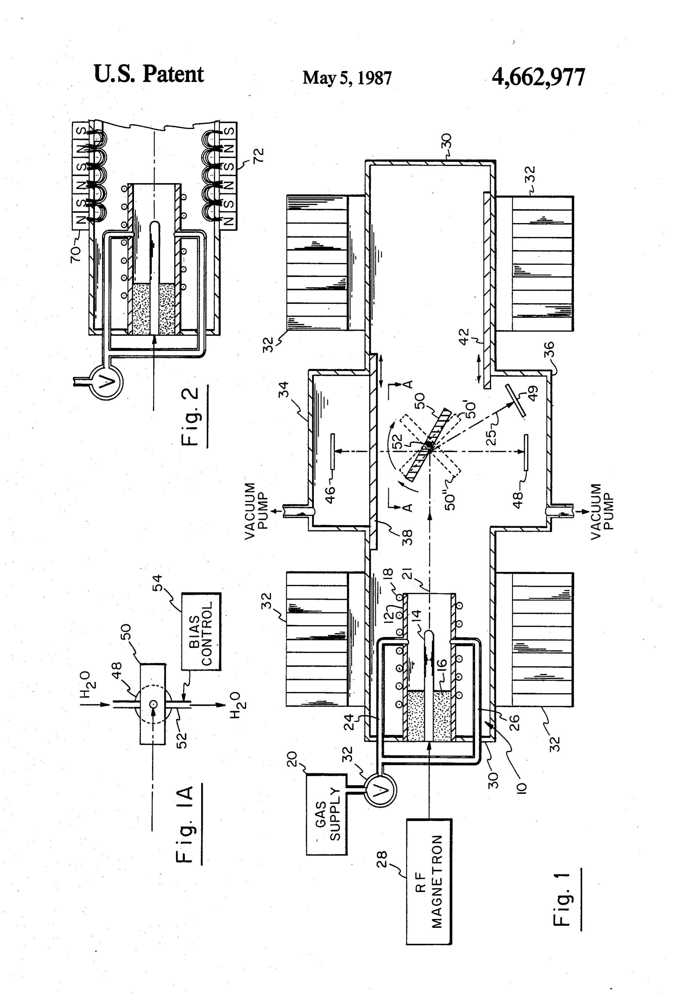
called the barrel etcher. It employs a resident plasma to BRIEF DESCRIPTION OF THE DRAWINGS erode the substrate's surface, which plasma generally exhibits a density of approximately 1010 cm3 at energy 15 FIG. 1 is an overall schematic of the invention. levels in the 1-3 eV range. Such barrel etchers are effec FIG. 1a is a plan view taken along lines A-A which tive but are relatively slow in their action. Moreover, shows the neutralizing plate and an underlying sub the use of charged particles for etching often tends to Strate.
charge the substrate being etched, which charge may FIG. 2 is a partial view of a portion of FIG. 1 wherein alter the etch profile, or lead to voltage gradients which the electromagnets have been replaced by permanent may damage the performance of the device. 20 magnets.
One modification to the barrel etcher involves the use of a magnetically enhanced plasma wherein the plasma DETAILED DESCRIPTION OF THE density is increased 1012 cm-3 with energy potentials INVENTION greater than 100 eV. Obviously, the etching rate within Referring now to FIG. 1, a plasma source 10 is shown such a system is much more rapid; however, substrate 25 schematically and comprises an outer metallic cylinder surface penetration and damage occurs and additional 12, an inner electrode 14, and an alumina vacuum seal treatments are required to "heal' such damage. A still 16. Around the periphery of cylinder 12 are cooling further modification to the barrel etcher is called the "after glow" reactor wherein a gas is passed through a coils 18. A source of cooling water, not shown, is pro microwave discharge to create a plasma. The plasma 12 via therefor.
30 vided a valve
A gas supply 20 is connected to cylinder 22 and pipes 24 and 26. Central electrode drifts downstream into a reaction chamber; by the time 14 is fed from a high it reaches the reaction chamber, the plasma has recom (or klystron) 28. The power radio frequency magnetron bined into neutral gas atoms which are then employed 10 are preferably coated with surfaces metallic gold, of plasma source platinum or iridium to provide isotropic etching. The resulting atoms have to prevent surface erosion.
very low energies, e.g. on the order of 0.03-0.15 eV. 35 This structure is known as a "plasma gun' and has All of the above systems are designed to overcome the "activation' energy barrier (i.e. the energy required been described previously by one of the inventors to cause a specific physical or chemical reaction to hereto in an article entitled "Coaxial Lower Hybrid occur) of the substrate sought to be eroded. Typically, Plasma Source' by R. W. Motley, et al., Review of chemical bonds exhibit approximately 5-10 eV energy Scientific Instruments, Volume 50, No. 12, December bond levels. In order to affect those bonds, the activa 1979, pages 1586-1589. The contents of that article are tion energy barrier (which is generally some percentage incorporated herein by reference. of the chemical bond energy) needs to be exceeded. It is Plasma gun 10 is housed within an evacuated enclo not desirable to greatly exceed the chemical energy sure 30. Surrounding vacuum chamber 30 are a plurality bond as this may succeed in inhibiting the chemical 45 of electromagnetic torodial coils 32 which provide, bond alteration and potentially damages the surface. when energized, a generally linear magnetic field For that reason, it is desirable to utilize particles in etch aligned along the length of container 30. Coils 32 pro systems which have an energy range in the 1-50 eV vide a moderate magnetic field of 3 to 5 kiloGauss. A range and more preferably in the 1-15 eV range. Fur pair of erosion chambers 34 and 36 are respectively thermore, it is preferable to provide a particle etching 50 oriented on either side of vacuum chamber 30. Each of system wherein the etch capability is anisotropic and chambers 34 and 36 may be isolated from vacuum evidences etch aspect ratios in the 20 to 1 range or chamber 30 by pneumatically driven gate valves 38 or better. 42. In FIG. 1, gate valve 42 is open, exposing chamber Accordingly, it is an object of this invention to pro 36 to vacuum chamber 30 whereas gate valve 38 is vide a system for altering the surface of the substrate 55 closed thereby isolating chamber 34 from vacuum which employs neutral particles. chamber 30. Within each of chambers 34, 36, are carri It is a further object of this invention to provide a ers (not shown) which are adapted to position semicon neutral particle surface etcher wherein the energy of ductor wafers in predetermined orientations shown by the particles impinging upon the surface can be con wafers 46, 48 and 49. (Of course, other orientations are trolled. 60 also within the contemplation of this invention.) It is still another object of this invention to provide a Centrally located within vacuum chamber 30 is a surface etcher which can provide a substantially colli rotatable neutralizer plate 50, a top view of which is mated beam of neutral particles. shown in FIG. 1a. Neutralizer plate 50 is mounted for
Summary of the invention
rotation about axis 52 which, itself, is hollow to enable 65 the passage of cooling water. Neutralizer plate 50 is also
A plasma gun is described which is capable of creat hollow thereby enabling cooling water to circulate ing and directing a plasma towards a neutralizing plate. within it. While neutralizer plate 50 is preferably con The plate is comprised of a material which is chemically structed of copper, it is additionally coated with a film 4 of either gold, platinum or iridium for reasons which adapted for fine feature etching. Under such circum will be discussed below. Neutralizer plate 50 is movable stances, the semiconductor wafer to be etched is ori about axis 52 to a plurality of positions, two of which ented as shown at 49. If it is wished to strip a resist from 50' and 50', are shown in phantom. Bias control 54 wafer 48, (requiring a broad etching beam), neutralizing provides a dc bias to neutralizer plate 50 which may plate 50 can be oriented at a 45 degree angle as shown vary from plus 20 volts to minus 50 volts. in phantom at 50'.
The operation of this system will now be briefly de By closing gate valve 42; opening gate valve 38 and scribed. In order to actuate plasma gun 10, gas supply flipping neutralizing plate to position 50", the neutral 20 is vented into cylinder 12 by opening valve 22 (either atomic beam can be directed at semiconductor wafer 46 continuously or pulsed). Gas supply 20 may be either a O for further processing. In the meanwhile, wafers 48 single gas, or a combination of gases whose atomic and/or 49 can be removed and new wafers put in place. species are reactive with the surface sought to be Referring now to FIG. 2, a plurality of permanent eroded. The gas pressure supplied through valve 22 magnets 70 and 72 are oriented about the periphery of should approximate 10-3 to 10-2 Torr. Since the re chamber 30, end to end in a north, south manner, and mainder of vacuum chamber 30 is kept at approximately 15 have replaced electromagnetic coils 32. In essence, 10 Torr during continuous operation or somewhat permanent magnet 70 and 72 provide cusp-like fields less than 10-5 Torr for pulsed operation, a positive which act to confine the plasma in its travel toward pressure differential is thereby created. RF magnetron neutralizing plate 50. If it is required, additional steering source 28 is then energized and applies its signal to magnets can be emplaced (not shown) at or near neu central electrode 14. RF magnetron source 28 prefera 20 tralizing plate 50 to control the configuration of the bly provides a signal frequency of 2.5 GHz at power plasma as it reaches the locale of plate 50. In such a range of 1 to 50 kilowatts. This produces an intense manner, the configuration of the reflected neutral plasma beam, on the order of 10 amps, with a plasma atomic beam can be readily controlled. If necessary, density approximately 101 cm-3. The resultant high additional collimating structures such as cylinders, ap intensity, dense plasma, emanates from the mouth of 25 erture plates or other collimating devices can be used to cylinder 12, in the direction indicated by center line 21. further direct and confine the neutral atomic beam after The plasma is confined and directed by the field lines reflection from plate 50. It also may be desirable to emanating from coils 32 towards neutralizing plate 50. shape neutralizer plate 50 to enhance the directivity of As the plasma approaches neutralizing plate 50, an the beam (e.g. slightly curved).
effect occurs called surface neutralization. When an ion 30 The types of beams that may be employed in the approaches a conductive metallic surface, an electron is above described apparatus include atomic species such attracted from the surface and neutralizes the ion into its as oxygen, chlorine or hydrogen and molecular species atomic or molecular neutral state. The atom or mole such as O2, CL2, H2, or HCL and various radicals. The cule so neutralized then impacts upon the surface of beams can have a central energy in the range of 1 to 50 neutralizing plate 50 and is physically deflected. The 35 eV with a spread energy of about 20%. Substantial Au, Pt or Ir coating on neutralizing plate 50 is required neutral beam fluxes can be achieved exceeding even so that there is a maximum of mismatch between the 1017 cm2 second -1. The erosion rate for an oxygen low mass incoming particles and the atoms wich make beam on graphite carbon at these energies and fluxes has up the surface of the plate. In specific, when the low been estimated to be aproximately 100 Angstroms per mass particles hit the much more massive surface atoms, second.
few surface atoms are dislodged (if any) and the greatest As an example, if one wishes to etch silicon preferen fraction of the lower mass particles are reflected. tially over its oxide, the gases used would preferably be In order to control the energy of the reflected neutral 90-95% C2F6 with the balance being oxygen. If you atoms, a bias is applied to neutralizing plate 50 which wish to etch aluminum preferentially which is emplaced bias either accelerates the ions as they approach the 45 on resist covered silicon, an approximate 50/50 mixture plate or decelerate them in accordance with the sense of chlorine and boron trichloride would be employed to and level of bias voltage. Thus, the energy of the re which a small amount of oxygen may be added depend flected atoms, even though neutral, can be very pre ing upon the resist employed. To etch silicon nitride the cisely controlled by altering the bias applied to the admitted gas would comprise 85% CF4 or C2F6, and the neutralizing plate. In sum, the energy of the reflected 50 balance 10% argon and 5% oxygen: or for higher spe neutral atoms can be controlled so that they just achieve cies NF3 or SF6 may be substituted for CF4 or C2F6. the desired energy to overcome the activation energy In summary, this invention avoids the charging of barrier of the material being eroded. exposed surfaces, enables the energy of the etching It should be understood that the reflected beam is one beam to be very precisely controlled, and provides at of neutral atoms and is to be distinguished from a neu 55 the surface to be etched, a flux of neutral atomic and tralized ion beam known in the prior art. In the latter, molecular particles hithertofore unachievable. electrons are sprayed into an ion beam to neutralize the We claim:
beam as a whole but not to necessarily neutralize the 1. Apparatus for altering the surface of a substrate, individual particles. In such a neutralized ion beam, the combination comprising:
while there are equal numbers of ions and electrons, no 60 plasma means for creating a dense plasma of ions substantial binding therebetween occurs to create neu from an injected gas and directing said plasma tral atomic particles. The neutralization process de along a first path;
scribed herein creates bound neutral atoms. metallic reflector means having a surface positioned When neutralization plate 50 is oriented as shown in in said first path, said surface being comprised of a FIG. 1, the angle of incidence along direction 21 is 65 material which is chemically inert and whose shallow as is the angle of reflection along direction 25. atoms are substantially heavier than the atoms of In such circumstances, the reflected neutral atomic said injected gas, said surface acting to provide beam remains relatively collimated and is especially electrons to combine with said ions to produce 5 neutral gas atoms and molecules to reflect physi 5. The invention as defined in claim 4 wherein said cally said neutral atoms and molecules along a metallic reflector means is movable so that said second second path towards said substrate, whereby the path can be altered.
6. The invention as defined in claim 1 wherein said surface of said substrate is bombarded by said re 5 surface material is selected from the group consisting of flected neutral atoms and molecules. gold, platinum and iridium.
2. The invention as claimed in claim 1 further includ 7. The invention as defined in claim 6 further includ ing means for magnetically confining and directing said ing enclosure means for enclosing the apparatus defined plasma. in claim 1 in a vacuum environment. 3. The invention as defined in claim 2 wherein said O 8. The invention as defined in claim 7 wherein said plasma means includes a source of radio frequency sig plasma means is adapted to produce a plasma density of better than 101 cm-3 in a range of energies between 1 nals to cause said injected gas to discharge and ionize. and 50 eV.
4. The invention as defined in claim 3 including 9. The invention as defined in claim 8 further includ means to apply a dc bias voltage to said metallic reflec 5 ing means for creating a region of lower vacuum in the tor means, said voltage acting to control the energy of vicinity of said plasma means and higher vacuum in the the atoms and molecules directed along said second vicinity of said metallic reflector means. path. k Sk k c
Provenance
- Collection
- Patents citing this work
- Pages
- 5
- Method
- pdftotext (the PDF's own text layer) + pdftoppm 300dpi page scans
- Patent office record
- patents.google.com →
- Source
- Google Patents citing-documents table
- Assignee
- University Patents, Inc.
- Published
- 1987-05-05
- Transcribed from
- patentimages.storage.googleapis.com →