

patent · US4670113A
Electrochemical activation of chemical reactions
2 June 1987
Text
Page 1bibliographic recordscan →
United States Patent (19)
Lewis
(54) ELECTROCHEMICAL ACTIVATION OF
CHEMICAL REACTIONS
Inventor: Arlin C. Lewis, P.O. Box AU, Libby,
Related U.S. Application Data (63) Continuation-in-part of Ser. No. 666,542, Oct. 30, 1984, abandoned.
(51) Int. Cl." ................................................ C25B 1/0 (52) U.S. C. ...................................... 204/80; 204/129;
(58) Field of Search ......................... 204/129, 101, 80;
4,158,637 6/1979 Jones ............................... 208/449 R.
4,171,247 10/1979 Harang et al. ........................ 204/34
4,268,363 5/1981 Coughlin ............................... 204/39
Titt E2
4,279,710 7/1981 Coughlin ............................. 204/10 4,302,320 1 1/1981 Lewis .......... ... 204/278 4,341,608 7/1982 St. John ...... ... 204/129 4,389,288 7/1983 Vaughan ............................. 204/101 4,412,893 11/1983 Fray et al. ... ... 204/105 R 4,425,203 1/1984 Gray ........ ... 204/29 4,555,317 11/1985 Nicolas................................ 204/129
FOREIGN PATENT DOCUMENTS
57-192274 11/1982 Japan ................................... 204/129 Primary Examiner-R. L. Andrews
Attorney, Agent, or Firm-Bacon & Thomas
A process for the gasification or combined gasification and liquefaction of carbon or carbonaceous materials by utilizing electrochemically generated atomic hydrogen to activate the chemical reaction between the ions of dissociated water and the carbon or carbonaceous mate rial in an electrolysis cell, thereby producing gaseous or
combined gaseous and liquid products in amounts ex
ceeding the Faraday equivalents of such products for the amount of electrical energy consumed.
28 Claims, 4 Drawing Figures
map
COOANT
OULET
Drawings
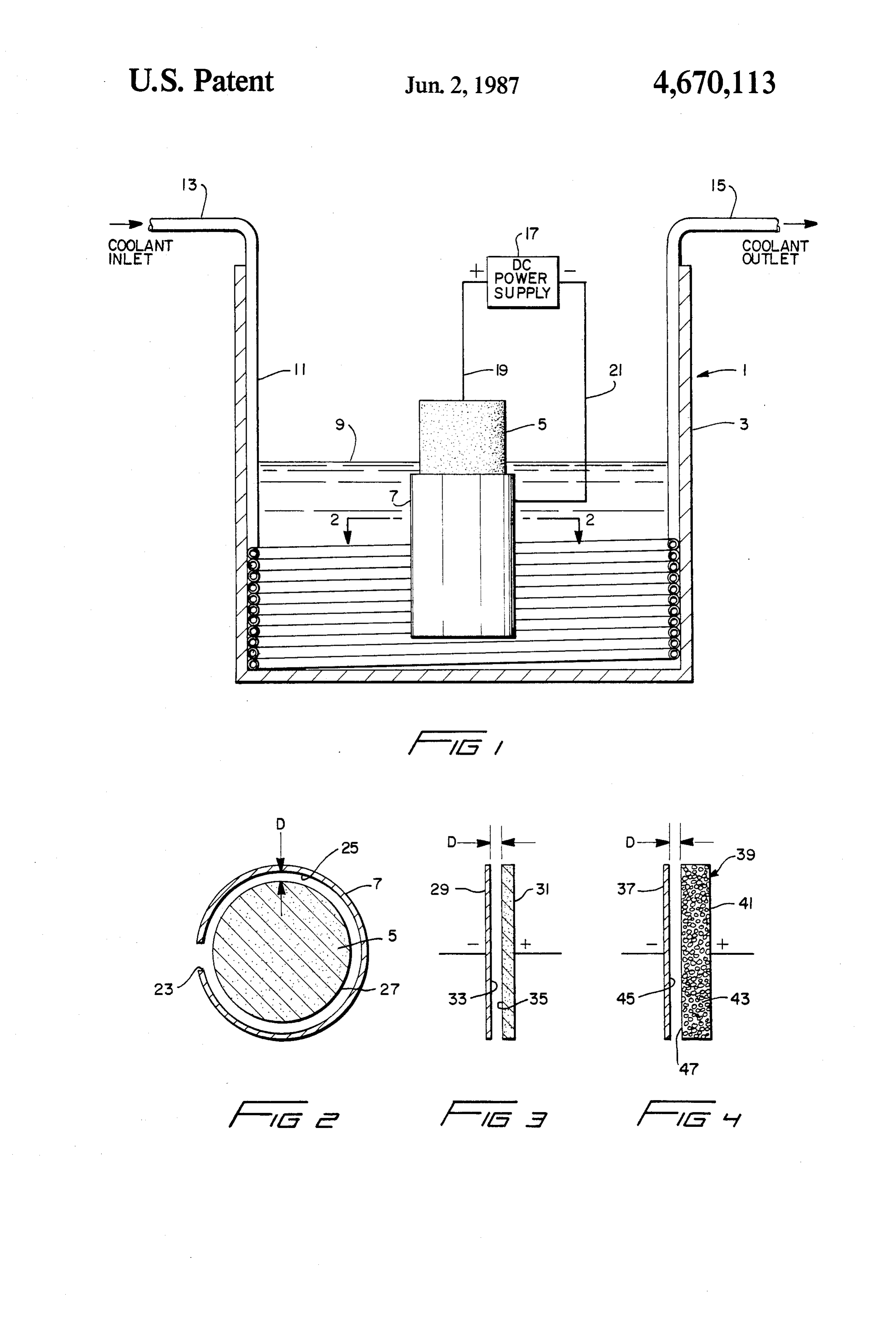
FIG. 1 is a schematic diagram of a preferred embodi corresponding to the previously described spacing pa ment of an apparatus in the form of an electrolytic cell rameters.
Page 2drawing sheetscan →
Page 3scan →
process which can also be applied to other carbona
ELECTROCHEMICAL ACTIVATION OF ceous materials such as wood wastes, bagasse and other CHEMICAL REACTIONS renewable resources would be a very useful addition to the chemical technology extant today.
CROSS REFERENCE TO RELATED 5 It is well known that hydrogen electrochemically APPLICATION generated at a cathode is generated as H (atomic hy
This application is a continuation-in-part of applica drogen) by the combination of an electron (e-) fur tion Ser. No. 06/666,542, filed on Oct. 30, 1984, now nished by the cathode and a hydrogen ion (H+) fur abandoned. nished by the electrolyte. Hydrogen gas (H2) results 10 from the combination of two units of atomic hydrogen
BACKGROUND OF THE INVENTION to form the H2 molecule. Since H2 has limited solubility 1. Field of the Invention in aqueous electrolytes, it precipitates from solution to The present invention generally involves the field of form H2 bubbles which rise to the surface of the electro technology relating to chemical reactions known as lyte and may be collected as hydrogen gas. It is also oxidation-reduction reactions. More particularly, the known that electrochemically generated atomic hydro invention relates to the activation of such reactions by gen is a powerful, though very transient, chemical electrochemically generated atomic hydrogen. agent. It is thought to be an important intermediate in 2. Description of the Prior Art the chemical reduction of chromic acid during chro It is known to electrochemically generate hydrogen mium electroplating from chromic acid solutions. At and either carbon dioxide or carbon monoxide gases 20 tempts have been made to diffuse electrochemically through an oxidation-reduction reaction. This may be generated atomic hydrogen through metal tubes or accomplished in an electrolytic cell environment by membranes to emerge at a metal-solution interface anodic oxidation of carbon and cathodic reduction of where it will provide a desired chemical reaction. In hydrogen ion in an aqueous acidic electrolyte. In this 25 general, these and other efforts to gain physical control process, the anode is consummable and formed of an of atomic hydrogen and allow its efficient use in desired appropriate carbonaceous material, such as coal, lignite, chemical reactions have been unsuccessful as compared active carbons, coke and the like. The cathode is not to other methods of carrying on the reactions. Even consummable and formed of copper, iron or other such chromium plating is an inefficient example of the use of suitable material. These electrodes are immersed in the aqueous acidic electrolyte contained within an electro 30 atomic efficient hydrogen as the operation is only 14% to 18% in electrochemical energy use. Thus the long lytic cell, wherein the latter is typically subdivided into sought after method of utilizing the powerful chemical separate anolyte and catholyte chambers by an ion per activity of atomic hydrogen in a wide variety of chemi meable membrane or a porous barrier which prevents or minimizes mixing of the anolyte and catholyte por cal reactions has not been heretofore realized. p tions of the electrolyte. When an electrical potential of 35 SUMMARY OF THE INVENTION sufficient voltage is applied across the electrodes from a It is the primary object of the present invention to direct current power source, oxidation of a carbona ceous anode produces oxides of carbon, and reduction provide to cause a system employing electrochemical activation desired chemical reactions to proceed in a of hydrogen ion at the cathode produces hydrogen.
It is also known that the aforedescribed electrochemi 40 manner so as to yield significantly greater quantities of cal reaction may be catalyzed or otherwise improved chemical products than would conventionally be real through the addition of various agents to the electrolyte ized in the absence of such activation. in order to affect the rate of oxidation of the carbona It is another object of the invention to provide a ceous material or to lower the half cell voltage required system for the production of hydrogen and carbon mon oxide through electrochemical activation of the reac for oxidation to occur, thereby increasing the amount of 45 tion current passed through the cell for a given operating of carbon and water.
voltage. Conventional electrochemical processes of this system It is a further object of the invention to provide a type have essentially been constrained to a strict adher for the hydrogenation or hydrogenation and ence to Faraday's Law wherein, for a given amount of partial oxidation of complex solid chemical compo electrical current utilized to drive the reaction, a fixed 50 nents, such as those found in coal, wood or other such maximum volume of gas can be generated when the biomass, to convert them to gaseous and liquid chemical operation is 100% efficient. This limitation has there products.
fore rendered heretofore known techniques for the It is yet another object of the invention to provide a electrochemical gasification of carbonaceous materials system for the employment of electrochemical proce impractical for the joint production of hydrogen and 55 dures to produce gaseous and liquid chemical products oxides of carbon. This is because, notwithstanding the in volumes significantly exceeding those volumes which utilization of catalyzed reactions, the volume of gas are conventionally realized for the same amount of produced does not justify the cost of the electrical en electrical energy consumed.
ergy consumed. It is still a further object of the invention to provide a In addition, the aforedescribed electrochemical reac- 60 system for the controlled employment of atomic hydro tion is a gasification reaction only. The objective of gen to activate and/or participate in chemical reactions. breaking the complex molecules present in coal, wood These and other objects of the invention are realized or other carbonaceous materials into desired liquid through the reaction of various types of carbonaceous products useful in the chemical industry has not hereto material in an electrolytic cell environment wherein a fore been realized electrochemically. A number of 65 carbon-containing consummable anode and a metallic methods of coal liquefaction are available but are costly nonconsummable cathode are immersed in an aqueous to operate and are therefore of questionable economic acidic electrolyte. The space between the electrodes is value. A low cost coal gasification and liquefaction devoid of any membrane or obstruction so as to permit 4 free communication of reaction components through through a pair of electrical conductors 19 and 21, re out the electrolyte. The cell is preferably provided with spectively.
an appropriate heat exchange means to remove excess The configuration of anode 5 and cathode 7, and their heat generated during the electrochemical and chemical disposition with respect to each other shall now be reactions. described with reference to FIG. 2. As seen therein, The specific configurations and characteristics of the anode 5 is of a solid cylindrical configuration, while electrodes may vary and encompass conventional elec cathode 7 is in the form of a tubular configuration and trode structures that are well known in the art. When an substantially entirely surrounds anode 5 and is spaced electrical potential is applied to the cell, conventional therefrom. Cathode 7 is provided with a longitudinal electrochemical reactions are initiated at the anode and 10 slot 23 which creates a fluid pumping action during cathode. Thereafter, a chemical reaction occurs at the gasification so that electrolyte may be continuously anode which yields quantities of both hydrogen and directed into the space between anode 5 and cathode 7. carbon containing products equal to or greater than the As is apparent in FIG. 2, cathode 7 includes an interior quantities produced by the electrochemical reactions. surface 25 that is spaced from an exterior surface 27 of The rate of this chemical reaction may be significantly 15 anode 5 by a distance D. Since surfaces 25 and 27 are enhanced through the addition of an activator enhance substantially the only exposed portions of the electrode ment agent to the electrolyte, wherein such agent pref surfaces disposed opposite each other, the application of erably includes a hydride-forming free metal or com an electrical potential across anode 5 and cathode 7 pound thereof. The cell configuration preferably in causes substantially the entire electrochemical gasifica cludes sufficient free board space disposed above the 20 tion reaction to actively occur between surfaces 25 and electrolyte level to accommodate any foaming of the 27, and the activated chemical reaction occurs at sur electrolyte produced by the active evolution of product face 27. The actual spacing of surface 25 from surface 27 gases. This foaming may be minimized by the addition is on the order of up to approximately one and one-half of a defoaming agent to the electrolyte, thereby further inches for distance D when an activator enhancement increasing the amount of gas produced by minimizing 25 agent is used, though preferably within the range of gas polarization or gas masking of the carbonaceous approximately one-sixteenth to three-sixteenth inch reactant. either with or without an activator enhancement agent. Further objects, features and attributes of the inven An electrode configuration according to a second tion shall become apparent from the following detailed embodiment of the invention shall now be described description thereof and appended claims, reference 30 with reference to FIG. 3. In this instance, a metal cath being made to the accompanying drawings forming a ode 29 and a carbon-containing anode 31 are each of a part of the specification, wherein the reference charac substantially planar configuration. Cathode 29 includes ters designate corresponding parts of the several views. an active surface 33 which is spaced from a correspond BRIEF DESCRIPTION OF THE DRAWINGs ing opposed active surface 35 of anode 31. Surfaces 33 35 and 35 are also spaced from each other a distance D
FIG. 1 is a schematic diagram of a preferred embodi corresponding to the previously described spacing pa ment of an apparatus in the form of an electrolytic cell rameters.
system which may be utilized in the practice of the An electrode configuration according to a third em invention to produce hydrogen, oxides of carbon and bodiment of the invention is shown in FIG. 4 and in other gases from carbonaceous-materials; cludes a cathode 37 having a planar configuration and a FIG. 2 is a cross-sectional view taken along the line corresponding anode 39 in the form of a rectangular 2-2 of FIG. 1; shaped perforated metal container 41 filled with carbon FIG. 3 is a schematic diagram, taken in cross section, or suitably prepared coal or biomass particles 43. Con depicting an electrode configuration according to a tainer 41 may be titanium or any other suitable metal second embodiment of the invention; and 45 known in the art for this purpose. It is also preferable FIG. 4 is a schematic diagram, taken in cross section, that some means be provided for continually replenish depicting an electrode configuration according to a ing particles 43 as they are consumed during the gasifi third embodiment of the invention. cation process. In this electrode configuration, cathode
Detailed description of the
37 includes an active surface 45 which is spaced from an 50 opposed active surface 47 of anode 39 by the spacing
PREFERRED EMBODIMENTS designated distance D.
An electrolytic cell system 1 which may be used to The aforedescribed electrode configurations are to be practice a preferred embodiment of the invention shall construed as merely preferred examples of any of a now be described with reference to FIG. 1. System 1 variety of configurations which may be deemed suitable includes a chamber within which an anode 5 and a 55 for the practice of the invention. The anode may of cathode 7 are immersed in a volume of aqueous electro course be formed of carbonaceous material, such as lyte 9. The height of chamber 3 should be such as to coal, coal chars, lignite, coke, carbon black, graphite, provide substantial freeboard space above the surface of cellulose, wood, biomass or the like and combinations electrolyte 9 for accommodating foam generated during of same. The cathode is preferably of copper or any the gasification and chemical reaction processes. Cham 60 other metal deemed suitable for the reactions of the ber 3 is also preferably provided with an appropriate gasification or gasification and liquefaction process. heat exchange means such as a tubular coil 11 through The aqueous electrolyte may preferably comprise a which fluid coolant may be circulated from an inlet 13 solution of sulfuric acid and water in varying ratios of to an outlet 15 for the purpose of removing heat gener concentration. A preferred concentration range would ated during gasification and maintaining electrolyte 9 at 65 encompass those concentrations between 2.7 to 15 Nor an optimum process temperature. Electric potential is mal H2SO4.
applied across anode 5 and cathode 7 by a suitable di The gasification or gasification and liquefaction pro rect current power source 17 connected thereto cess may optimally be conducted within a temperature 5 range of approximately 175' F. to 200 F., though pref maintenance of the reaction can be realized through erably at 180° F. to 200 F. Conducting the process at a appropriate replenishing of water in the electrolyte and temperature in excess of the boiling point of the electro carbon in the anode, the two components consumed by lyte would be possible provided the system is placed the process.
under an appropriate pressurized condition. The combined gasification and liquefaction process is The electrical potential applied across the electrodes more complex and involves hydrogenation and partial by a suitable direct current power source is preferably oxidation of the carbonaceous material. In addition to within the approximate range of 1.8 to 3.2 volts and a the above described reaction of carbon and water, a current density of approximately 1.0 to 12.0 amps per second type of reaction occurs wherein atomic hydro square inch. Due to the nature of the invention, the O gen reacts with or activates certain points on large starting current density for initiating the electrochemi molecules to break them into smaller active molecules cal reaction may be approximately 10 amps per square inch and thereafter reduced to approximately 6 amps which or of subsequently exhibit the effects of hydrogenation hydrogenation and partial oxidation.
per square inch or less as an operating current density during the subsequent combined electrochemical and 5 practice of the invention asresults The new and unexpected realized through the disclosed herein can be chemical reactions.
attributed to several observations. The employment of
MODE OF OPERATION an electrolyte containing a substantial concentration of In the operation of electrolytic cell system 1 accord an ion, for example SO4, which is known as a "poi ing to the invention, an electrical potential is applied 20 son' or inhibitor for the reaction H--H-H2 serves to from power supply 17 across anode 5 and cathode 7 prolong the the longevity of cathodically generated H in electrolyte and therefore renders same available for through conductors 19 and 21. Sufficient voltage is reaction activation. Moreover, the employment of a required to initiate the basic electrochemical reaction strong acid electrolyte which provides a high concen involving oxidation of carbon at the anode and reduc tion of water at the cathode, which reaction is expressed 25tration of H+ ion and a correspondingly low concentra as follows: tion of OH ion constitutes a proper chemical environ ment for the desired reactions to proceed. It was further observed that control of the electrodes spacing distance
D within a range of one and one-halfinch or less, except
This reaction liberates oxides of carbon, specifically 30 in those instances wherein a hydride forming metal is carbon monoxide, at the anode, while hydrogen gas is included in the electrolyte to permit greater spacing liberated at the cathode. The half cell reactions may be distances, served to significantly increase the produc expressed as follows: tion of atomic hydrogen. When a hydride forming metal At the cathode: is utilized as an activator enhancement agent, the con 35 centration of the metal in the electrolyte is within a range which yields a "spongy' or "mossy" nonadherent electrodeposit with high surface area for acceptance of hydrogen at the cathode and release of hydrogen as H wherein H is atomic hydrogen. in the anode area as the metal hydride particles decom At the anode: pose to metal which is subsequently dissolved by the acid electrolyte, thereby releasing an additional supply of H which activates the heretofore described chemi cal reactions.
It is important to note that H is a product of the The advantage of this system resides in the high out electrochemical reaction and is both highly reactive and 45 put production of gas or gas and liquids with very low of transient life. The H is an activator species which electrolysis energy requirements, thereby producing a causes a subsequent chemical reaction to occur in the gasification and liquefaction process that exceeds a system for simple carbon gasification as follows: strictly electrochemical process in efficiency by over
50 While the invention is operable without the use of activator enhancement agents, those agents increase the which may be written in the form: efficiency of the process and minimize the engineering problems in designing production type equipment.
Nickel, cobalt, iron and copper are suitable for use as 55 activator enhancement agents. These metals can be electrodeposited as sponge metal deposits, form unsta ble metal hydrides with electrochemically generated atomic hydrogen and, as metal particles after hydride
This chemical reaction has been discovered to be decomposition, dissolve in the electrolyte to repeat the self-sustaining, notwithstanding a reduction of the elec 60 cycle as sponge metal deposits at the cathode. These trical potential required for initiating the aforemen metals can be used individually or in combination with tioned electrochemical reaction, while simultaneously each other. Nickel sulfate has been found to comprise generating an amount of gas far in excess of that nor an especially suitable compound for introducing a metal mally realized through the electrochemical reaction hydride forming agent to the electrolyte. alone. The chemical gasification reaction was found to 65 While the metal hydride is unstable at the tempera be continuously self-sustaining under minimum electri ture maintained in the cell and decomposes to metal cal energy requirements until the reaction terminates particles and H in a finite time in the body of the elec due to depletion of the reaction components. Continual trolyte, it becomes more unstable in the chemical atmo 6 sphere known as the "anode film' which surrounds the device. The active anode area was 12 square inches and anode during electrolysis. Thus, while a certain portion the electrolyte volumes varied from about 1 to 1.3 liters of the metal hydride may release its H" in the body of in all examples.
the electrolyte, a major portion of the H release occurs EXAMPLE 1. in the immediate vicinity of the carbonaceous anode 5 where it becomes the activating agent for the chemical The electrodes included a carbon anode and a copper reaction between the carbonaceous material and water. cathode, and spaced a distance of 3 inches apart and the In effect, the metal hydride functions as a carrier for electrolyte composition was 2.7N H2SO4. The electro transferring H from the cathode film to the anode film lyte temperature was maintained at 180' F. At a cell in the electrochemical system. 10 voltage of 2.4 volts, the cell amperage was observed to The activator enhancement agent may be incorpo be 121 amps, and this resulted in a gas production of 3.2 rated into the reaction in several ways. Preferably, an cubic feet per hour or 0.026 cubic feet per ampere-hour. appropriate metalsalt may be introduced into the reac As this example clearly illustrates, the results were tor as a minor constituent of the electrolyte. Alterna typical of conventional electrolysis wherein the amount tively, a small amount of the metal salt or free metal 15 of gas produced per ampere-hour corresponds approxi may be directly incorporated into the carbonaceous mately to that predicted by application of Faraday's material making up the anode, in the form of particles or Law.
a thin wire, so that the agent is anodically dissolved and EXAMPLE 2 thereby metered into the electrolyte during the reac tion. Also, a second electrochemical circuit may be 20 In this example, the carbon and copper electrodes provided with a metal suitable as an activator enhance were also spaced a distance of 3 inches apart, but the ment agent as the anode and with the cathode of the electrolyte composition was 5N H2SO4. An activator primary circuit serving as the common cathode for both enhancement agent was added, which agent comprised circuits. The current in the second circuit is controlled NiSO4. 6H2O in a concentration of 83 grams per liter. to add the activator agent to the electrolyte as needed. 25 The electrolyte was maintained at a temperature of 200 A suitable concentration of activator enhancement F. Under these conditions, an application of 1.3 volts agent has been found to comprise approximately 100 resulted in a cell amperage of 110 amps. This produced grams NiSO4. 6H2O per liter of electrolyte. The elec 7.0 cubic feet per hour of gas or 0.064 cubic feet per trolyte may also be precharged by dissolving a nickel ampere-hour.
anode in solution to reach an equivalent Nit-2 concen 30 This example illustrates an application of the present tration. invention wherein an activator enhancement agent in As previously indicated, foaming often occurs during the form of nickel salt was added to the electrolyte, thus the gasification and liquefaction process, with the foam resulting in a volume of gas production which was accumulating within the freeboard space above the several times greater than that predicted by application surface of electrolyte 9 in chamber 3. This situation has 35 of Faraday's Law.
been found to inhibit gas production. It has been discov EXAMPLE 3 ered that minimizing or eliminating the accumulation of foam results in a significant increase in gas and liquid The carbon and copper electrodes were spaced 1/16 production. This is preferably accomplished by adding inch apart and the electrolyte composition was 5N a defoaming agent to the electrolyte. Any suitable de 40 H2SO4 maintained at a temperature of 180° F. An ap foaming agent may be used for this purpose, but pre plied cell voltage of 2.6 volts resulted in a cell amperage ferred agents are those containing parabens. In addition, of 128 amps. This produced a gas volume of 20 cubic small quantities of acetone and methylethylketone may feet per hour or 0.156 cubic feet per ampere-hour. be added to the agent to permit the latter to be easily This example illustrates the effect of practicing the dissolved in the electrolyte. A suitable concentration of 45 invention without the addition of an activator enhance a defoaming agent may comprise 8 ounces of the agent ment agent to the electrolyte. Under this condition, the to each gallon of electrolyte. electrodes were maintained at the close spacing of 1/16
Examples
inch, thereby permitting the transient activator agent
H', which is produced at the cathode, to activate the
The invention shall now be described in further detail 50 carbon anode. Thus, the gas production per ampere by way of several examples which were performed by hour was six times greater than that realized in Example operation of an electrolysis cell. The cell was defined by 1 and over five times greater than that predicted by a one gallon glass jar provided with a screw type lid. Faraday's Law.
The anode was in the form of a cylindrical carbon rod EXAMPLE 4 suspended from the lid and provided with an electrical 55 lead extending therethrough. The cathode was also In this example, the carbon anode to copper cathode suspended from the lid and comprised of a copper sheet spacing was also maintained at a distance of 1/16 inch of inch thickness and provided with an electrical lead. and the electrolyte composition was 5N H2SO4 with The anode and cathode were supported in such a man added NiSO4. 6H2O at a concentration of 83 grams per ner that the spacing between their active surfaces could liter. The electrolyte temperature was 180° F. An ap be adjusted from a maximum of 3 inches to a minimum plied cell voltage of 2.5 volts resulted in an observed of 1/16 inch. A direct current electrical power source cell amperage of 126 amps. This produced 25 cubic feet with variable voltage control was connected to the per hour of gas or 0.198 cubic feet per ampere-hour. electrical leads of the electrodes. The gas generated by This example clearly illustrates that the gas produc the cell was conducted away by a tube sealed into a hole 65 tion rate can be further enhanced when the electrodes provided in the lid. The tube was connected to a gas are disposed at a close spacing from each other through conditioning and measuring train which included a gas the addition of a metal ion as an activator enhancement scrubber-cooler, drying column and a gas measuring agent. The rate of gas production per ampere-hour was
Page 7scan →
7.6 times that observed in Example 1, and far greater tion was 1 hour and 20 minutes with a dry gas produc than that expected by Faraday's Law. This example tion of 6.2 cubic feet and a liquid production of 414 demonstrates that a large portion of the gas produced milliliters collected in the first condenser. No liquid was during the process was directly caused by the presence found in the second and third condensers. The liquid of a chemical reaction. was analyzed and found to consist of the following by
Isopropyl alcohol: 22%
In this example, the carbon anode to copper cathode Isopropyl formate: 15% spacing was also maintained at a distance of 1/16 inch. Acetone: 11%
The electrolyte composition was 5N H2SO4 with 10 Acetic acid: 9%
NiSO4. 6H2O in a concentration of 83 grams per liter Water: 37% added to the electrolyte as the activator enhancement Undetermined or combined error in above quantities: agent. In addition, 30 milliliters of an antifoaming agent 6% was also added, which agent comprised the antifoaming Liquid from another, but identical, test run was tested composition sold under the trade name "Rug Doctor" 15 for energy value in a calorimeter and was found to for use in preventing foaming of carpet cleaning fluids. produce 7950 BTU per pound even though the water The electrolyte temperature was maintained at 200 F. content was not removed.
and a constant cell voltage of 3.0 volts was applied. The residue from the wood chips was removed from Observations and measurements were taken every 2 the cell at the end of the test run and washed and dried. minutes after the expiration of the first minute and for a 20 It consisted of black porous material in the spatial form total of 6 minutes. It was noted that after 1 minute, the of the original chips and exhibited good electrical con cell amperage was 110 amps and the gas volume pro ductivity.
duction was 15 cubic feet per hour or 0.136 cubic feet powder. ItThe dried material was crushed to a fine per ampere-hour. After 2 minutes, the cell amperage activated carbon found was and to have the characteristics of appeared to be a relatively pure was 100 amps and the gas production was 20 cubic feet carbon with the high surface area per hour or 0.200 cubic feet per ampere-hour. After 4 characteristic of activated carbon. required for activity minutes, the cell amperage was 96 amps and the gas production was 30 cubic feet per hour or 0.312 cubic tionThis example illustrates that the process of the inven feet per ampere-hour. After 6 minutes, the cell amper gases andproduce can liquids unexpectedly large quantities of useful from wood wastes which are available age was 95 amps and the gas production was 30 cubic 30 in large quantities in many parts of the world. A form of feet per hour or 0.316 cubic feet per ampere-hour. activated carbon also results from the process. This example illustrates the increased efficiency with elapsed time of gas production when an antifoaming EXAMPLE 7 agent and activator enhancement agent are both present In this example the apparatus, electrolyte composi in the electrolyte. After an elapsed time of 6 minutes, 35 the gas production rate per ampere-hour was 12.2 times tion and wood chip feed were exactly the same as in that observed for Example 1. It is therefore apparent Eample 6. The electrolyte temperature was maintained that the results derived from Examples 2-5 clearly es at 198 F. The cell was not electrolyzed. A stream of tablish the significant advantages made possible by the gas collected from previous test runs identical to that of practice of the invention when compared to the results 40 Example 6 was sparged through the cell electrolyte at realized through practice of the prior art procedure the rate of 6.2 cubic feet over a period of 1 hour and 20 demonstrated in Example 1. minutes. A small quantity of noncombustible liquid was The gas productions in the aforediscussed examples collected in the condensers.
were only measured for volume on a dried basis as The residue from the wood chips was brown colored indicated, and not analyzed for composition. However, 45 and otherwise unchanged from the original feed mate the gas productions in many other similar test runs with rial. It could not be crushed into a powder by the proce the same apparatus were analyzed and found to be prin dure used in Example 6 and therefore did not warrant cipally comprised of hydrogen and carbon monoxide, testing for possible use as activated carbon. The results along with small quantities of carbon dioxide and very of this test illustrate that electrolysis under the condi small quantities of nitrogen. 50 tions which describe the invention is necessary to obtain the type and quantity of products which resulted from
EXAMPLE 6 the operation of Example 6.
In this example, three water cooled condensers were EXAMPLE 8 placed in series in the gas-vapor outlet line from the cell.
Their position was between the cell and the previously 55 In this example, three water cooled condensers were described scrubber, dryer and gas measuring meter. The also in place in the gas-vapor outlet line from the cell. carbon anode to copper cathode spacing was main The anode was cut from a slab of pitch bonded coal of tained at a distance of 1/16 inch. The electrolyte com the type commonly used for cell linings or electrodes in position was 5N H2SO4 with NiSO4, 6H2O in a concen the aluminum industry. The anode to copper cathode tration of 83 grams per liter added to the electrolyte as 60 spacing was 3/16 inch at the beginning of the test and the activator enhancement agent. No antifoaming agent had increased to inch at the completion of the test due was used. A wood chip mixture comprised of pine to depletion of the anode material. The electrolyte tem wood, bark and needles, collectively simulating pine perature was maintained in the range from 196' F. to wood waste, was mixed into the electrolyte so that the 200 F. An applied cell voltage of 2.8 volts resulted in wood and bark particles were fully wetted by the elec 65 an observed cell amperage of 100 amps. The test dura trolyte. The electrolyte temperature was maintained at tion was 2 hours with a dry combustible gas production 198 F. An applied cell voltage of 3.8 volts resulted in of 7.8 cubic feet and a total liquid production of 1066 an observed cell amperage of 100 amps. The test dura milliliters in the three condensers, with approximately
Page 8scan →
75% in the first condenser, 20% in the second con 4. The process of claim 1 wherein the spacing be denser and 5% in the third condenser. tween the electrodes is within the range of approxi The liquid was analyzed in all three condensers and mately 1/16 to inch.
found to consist of the following by weight %: 5. The process of claim 1 further including the step of utilizing a consummable anode formed of carbonaceous material.
Condenser Condenser Condenser 6. The process of claim 1 wherein the carbonaceous # #2 #3 material is substantially entirely comprised of solid or Water 1.0% 22.0% 12.0% ganic hydrocarbons.
Formic acid
Methanol
O 7. The process of claim 1 including the step of adding
Ethanol 7.5% 57.6% 44.3% a defoaming agent to the electrolyte in an amount suffi Methyl formate 6.2% 1.7% 1.4% cient to at least substantially reduce any foaming of the Diethyl ether 4.4% 6.5% 5.1% electrolyte.
Ethyl formate 80.9% 8.6% 30.5% 8. The process of claim 7 wherein the defoaming 15 agent includes parabens.
The liquid was combustible and tested for energy 9. The process of claim 1 further including the step of value in a calorimeter which showed a value of 8750 maintaining the electrolyte at a temperature of from BTU per pound. approximately 175' to 200 F. This example illustrates the use of the invention as a 20 10. The process of claim 1 wherein the intensity of the coal gasification and liquefaction method whereby a electric potential applied across the electrodes is from dirty burning solid fuel is converted to clean burning approximately 1.8 to 3.2 volts.
gas and liquid products. Liquids derived from coal 11. The process of claim 1 wherein the current den through the practice of the invention are also useful as sity12.isThe from approximately 1.0 to 12.0 amps/inch2. process of claim 1 wherein the aqueous elec industrial chemicals.
It is to be understood that the embodiments and ex 25 trolyte includes sulfuric acid in a concentration of from amples of the invention herein shown and described are approximately 2.7 to 15.0N. 13. The process of claim 1 wherein the electrodes to be taken as merely preferred embodiments of the include a carbon anode and a metal cathode. same, and that various changes in the shapes, sizes, arrangement of parts, compositions, parameters and 30 14. The process of claim 1 wherein: methods of use and operation may be resorted to, with (a) the electrochemical oxidation-reduction reaction out departing from the spirit of the invention or scope is expressed as follows: At the cathode:
of the subjoined claims.
I claim
1. A process for the gasification or combined gasifica 35 tion and liquefaction of carbonaceous materials in an electrolytic cell including an anode and a cathode, the anode and cathode being immersed in an aqueous elec wherein H is atomic hydrogen. trolyte and provided with a direct current power At the anode:
source, comprising the steps of:
(a) disposing a carbonaceous material in the electro 20-2C-4e-2CO, and lyte;
(b) spacing the electrodes from each other at a dis (b) the chemical oxidation-reduction reaction is ex tance equal to or less than approximately one and pressed as follows:
one-half inches; 45 OH" -- H --C-H+H"--CO, and (c) applying an electrical potential of sufficient inten sity across the electrodes for causing an electro H-H'-H2.
chemical oxidation-reduction reaction wherein 15. A process for the gasification of combined gasifi oxidation occurs at the anode and reduction of cation and liquefaction of carbonaceous materials in an water occurs at the cathode to generate atomic 50 electrolytic cell including an anode and a cathode, the hydrogen and produce hydrogen gas; and anode and cathode being immersed in an aqueous elec (d) utilizing the atomic hydrogen for activating a trolyte and provided with a direct current power subsequent chemical oxidation-reduction reaction source, comprising the steps of:
whereby gasification or combined gasification and (a) disposing a carbonaceous material in the electro liquefaction of the carbonaceous material is real 55 lyte;
ized to produce a total amount of gaseous or com (b) adding an activator enhancement agent in the bined gaseous and liquid product in excess of that form of a hydride-forming metal or compound normally realized only through electrochemical thereof to the electrolyte;
reaction in accordance with Faraday's Law for the (c) applying an electrical potential of sufficient inten amount of electrical energy consumed. 60 sity across the electrodes for causing an electro 2. The process of claim 1 further including the step of chemical oxidation-reduction reaction wherein adding an activator enhancement agent in the form of a oxidation occurs at the anode and reduction of hydride-forming metal or compound thereof to the water occurs at the cathode to generate atomic electrolyte. hydrogen and produce hydrogen gas; and 3. The process of claim 2 wherein the activator en 65 (d) utilizing the atomic hydrogen for activating subse hancement agent includes a metal or a salt of a metal quent chemical oxidation-reduction reaction selected from the group consisting of nickel, cobalt, whereby gasification or combined gasification and copper and iron, or combinations thereof. liquefaction of the carbonaceous material is real 9 ized to produce a total amount of gaseous or com 24. The process of claim 15 wherein the intensity of bined gaseous and liquid product in excess of that the electric potential applied across the electrodes is normally realized only through electrochemical from approximately 1.8 to 3.2 volts.
reaction in accordance with Faraday's Law for the 25. The process of claim 15 wherein the current den amount of electrical energy consumed. 5 sity is from approximately 1.0 to 12.0 amps/inch2. 16. The process of claim 15 wherein the activator 26. The process of claim 15 wherein the aqueous enhancement agent includes a metal or salt of a metal electrolyte includes sulfuric acid in a concentration of selected from the group consisting of nickel, cobalt, from approximately 2.7 to 15.0N. 27. The process of claim 15 wherein the electrodes copper and iron, or combinations thereof. 10 include a carbon anode and a metal cathode. 17. The process of claim 15 wherein the electrodes 28. The process of claim 15 wherein: are spaced from each other at a distance equal to or less (a) the electrochemical oxidation-reduction reaction than approximately one and one-half inches. is expressd as follows: 18. The process of claim 17 wherein the spacing be At the cathode:
tween the electrodes is within the range of approxi 15 mately one-sixteenth to one-fourth inch.
19. The process of claim 15 further including the step of utilizing a consummable anode formed of carbona ceous material.
20. The process of claim 15 wherein the carbona wherein H is atomic hydrogen. ceous material is substantially entirely comprised of At the anode:
solid organic hydrocarbons.
21. The process of claim 15 including the step of 20-2C-4e-2CO, and adding a defoaming agent to the electrolyte in an (b) the chemical oxidation-reduction reaction is ex amount sufficient to at least substantially reduce any 25 pressed as follows:
foaming of the electrolyte.
22. The process of claim 21 wherein the defoaming agent includes parabens. and 23. The process of claim 15 further including the step of maintaining the electrolyte at a temperature of from 30 approximately 175' to 200 F.
Provenance
- Collection
- Patents citing this work
- Pages
- 9
- Method
- pdftotext (the PDF's own text layer) + pdftoppm 300dpi page scans
- Patent office record
- patents.google.com →
- Source
- Google Patents citing-documents table
- Assignee
- Lewis Arlin C
- Published
- 1987-06-02
- Transcribed from
- patentimages.storage.googleapis.com →