

patent · US4672949A
Solar energy collector having an improved thermal receiver
16 June 1987
Text
Page 1bibliographic recordscan →
54). SOLAR ENERGY COLLECTOR HAVING AN
IMPROVED THERMAL RECEIVER
Inventor: Mark J. O'Neill, Richardson, Tex. 73 Assignee: Entech, Inc., DFW Airport, Tex.
(51) Int. Cl. ................................................. F24J 2/08 52 U.S. Cl. ..................................... 126/440; 126/449
FOREIGN PATENT DOCUMENTS
555420 6/1923 France ... 126/440 2429976 2/1980 France ................................ 126/440 Primary Examiner-Randall L. Green
Attorney, Agent, or Firm-Harold E. Meier
A solar thermal energy collector includes a thermal receiver for receiving thermal energy from incident solar radiation and converting that energy, with mini mum heat loss, into thermal energy transferred to and carried by a thermal fluid in a copper conductor. The copper tube is placed within a lower aluminum extru sion and may be secured thereto with a metal-filled silicone adhesive. The adhesive also acts as a heat-trans fer device. The lower aluminum extrusion rests upon a foundation of isocyanurate urethane insulation which in turn rests upon the lower portion of a solar collector so that the central axis of the thermal fluid conducting tube lies along the axis of concentration of received solar energy. An upper aluminum extrusion is placed on top of the upper half of the copper tube and secured thereto with metal-filled silicone adhesive. The top surface of the upper aluminum extrusion is painted black and has a triangular-faceted surface. The faceted top surface of the upper aluminum extrusion is configured such that the triangular prisms run along an axis parallel to the central axis of the thermal fluid tube. A clear silicone layer is placed on top of the upper aluminum extrusion with its lower surface interlocked with the triangular faceted top surface of the upper aluminum extrusion. The clear silicone layer has a prismatic upper surface with the longitudinal axes of the prisms being arranged perpendicularly to the longitudinal axes of the facets along the top surface of the upper aluminum extrusion. 19 Claims, 2 Drawing Figures
Drawings
Page 2drawing sheetscan →
Page 3scan →
a prismatic upper surface and a triangular-faceted lower
SOLAR ENERGY COLLECTOR HAVING AN surface interlocking with the top surface of the upper IMPROVED THERMAL RECEIVER aluminum extrusion, is placed on top of the upper alumi num extrusion. The improved thermal receiver con
FIELD OF THE INVENTION struction disclosed herein provides a less expensive and The present invention relates generally to solar en more efficient thermal energy receiver which dramati ergy collectors and more specifically to an improved cally reduces heat loss from the receiver to the environ thermal receiver for use in solar energy collectors. ment, significantly reduces the front surface reflection loss of the receiver, and minimizes reflection losses from
BACKGROUND OF THE INVENTION 10 the black-painted absorber.
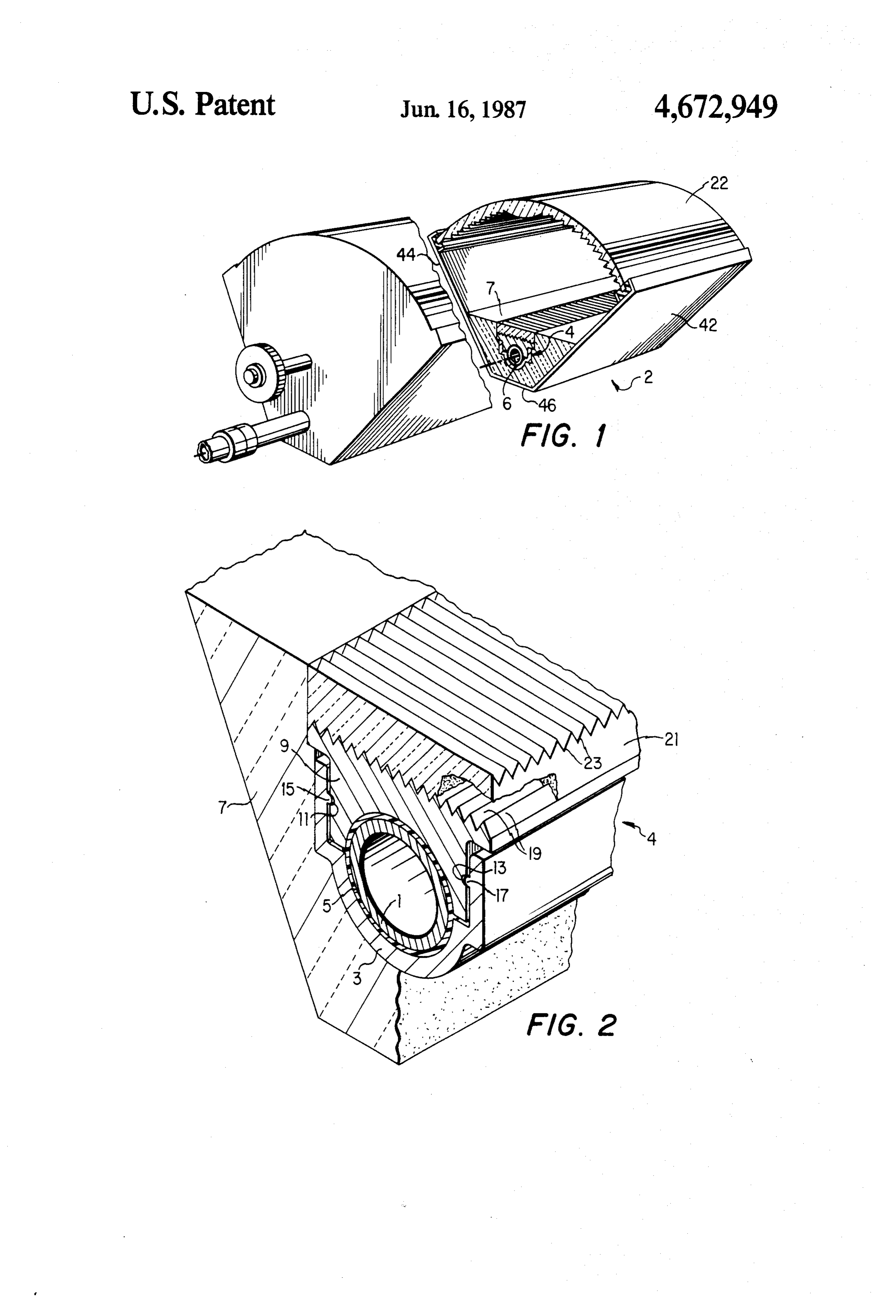
In the past, solar energy collectors, such as the one BRIEF DESCRIPTION OF THE DRAWING shown in the U.S. Pat. No. 4,069,812, which is included herein by reference, have provided a very effective and A better understanding of the present invention may efficient means of converting solar energy into both 5 be had from the following detailed description, when useful thermal energy by transferring heat to a working read in connection with the accompanying drawings, in fluid and/or useful electrical energy by means of solar which:
cells. As the state of the art advances in solar energy FIG. 1 is a cross-sectional view of the thermal collec collection, new and more efficient methods of heat tor and receiver of the present invention; and collection and solar conversion are constantly being FIG. 2 is a cut-away, cross-sectional view showing sought. Generally, improved collection systems have the details of the thermal receiver.
either increased the efficiency of the optical system for transforming light rays into usable energy, or improved DETAILED DESCRIPTION OF THE tracking systems for tracking the sun, or improved ther PREFERRED EMBODIMENT mal systems for collecting and retaining as much heat Referring in detail to FIG. 1, there is shown a thermal by a solar receiver as possible. The present invention is 25 solar collector 2 similar to the collector disclosed in the primarily concerned with the more efficient collection above-referenced U.S. Pat. No. 4,069,812, including and the retention of thermal solar energy by providing an improved thermal energy receiver for use within a collector housing walls 42, 44 and 46 and a linear Fres nel lens 22 supported by the walls 42, 44 and 46. A solar collector device.
Thermal inefficiencies in solar collectors can result 30 pre-formed insulation material 7 is supported by the from many causes. For example, while solar energy thermal walls 42, 44 and 46 and provides a space into which a may be efficiently collected and focused upon a thermal arrangedreceiverto focus device 4 is placed. The collector 2 is incident solar radiation along a focal receiver, much of that energy may subsequently be lost to the environment surrounding the receiver by radia axis 6 which extends along the longitudinal axis of the tive, convective and conductive heat transfer, since the 35 collector 2.
receiver will normally operate at a much higher temper forIntransporting
FIG. 2, a copper (or other suitable metal) tube 1 a heat exchange medium is disposed ature than the environment. Additionally, reflection losses are normally experienced at the black-coated along the focal axis 6. The tube 1 is placed within a receiver and at the surfaces of transparent covers over lower aluminum extrusion 3 and connected thereto with the receiver. Even when the solar receiver or absorber 40 a metal-filled silicone adhesive 5. The lower aluminum is black-coated, reflection losses still occur, albeit to a extrusion 3 rests upon a layer of isocyanurate urethane lesser extent. Moreover, prior attempts to alleviate heat (or other suitable low conductivity material) insulation losses in solar thermal receivers have more often than 7 which fills the volume between the lower aluminum not resulted in a more expensive product which is some extrusion 3 and the housing of a solar collector such as times deficient in other respects. For example, in order 45 the housing walls 42, 44 and 46 of the U.S. Pat. No. to reduce radiative heat losses, some receivers have 4,069,812.
utilized black chrome selective coatings which are less An upper aluminum extrusion 9 is constructed to be durable and more expensive than low-cost black paint. placed upon the top of the copper tube 1. In the present
Summary of the invention
example, the upper aluminum extrusion includes detents 50 11 and 13 for receiving corresponding bosses 15 and 17
An improved solar energy thermal receiver is herein of a lower aluminum extrusion or support structure 3. after described which provides significantly increased The upper extrusion 9 includes a black-painted, triangu efficiencies in transforming solar radiation into useful lar-faceted top surface 19. The peaks and valleys of the heat transported by a thermal fluid. A thermal fluid faceted top surface 19 are extended along the top sur conducting copper (or other metal) tube is placed upon 55 face of the upper extrusion 9 and run parallel to the a lower aluminum extrusion. A metal-filled silicone (or longitudinal axis of the collector 2. other thermally conductive) adhesive may be placed A clear silicone (or other transparent material with between the tube and the extrusion. The lower alumi low thermal conductivity) layer 21 has its lower surface num extrusion rests upon a pre-formed volume of isocy faceted to correspond to and engage with the faceted anurate urethane (or other low conductivity material) upper surface 19 of the upper aluminum extrusion 9. insulation which fills the space between the lower alu The silicone layer 21 includes a prismatic upper surface minum extrusion and the solar collector housing. An 23 with the longitudinal axes of the prisms running upper aluminum extrusion is secured to the upper half across the collector, i.e. perpendicularly to the longitu of the copper tube and includes a black painted, triangu dinal axes of the triangular facets engaging the lower lar-faceted upper surface. A metal-filled silicone (or 65 surface of the silicone layer 21 and the upper surface of other thermally conductive) adhesive is placed between the upper aluminum extrusion 9.
the copper tube and the extrusion. A clear silicone (or The thick layer of optically clear silicone polymer 21 other transparent low conductivity material) layer with above the metal absorbing surface of the top aluminum 4 extrusion 9 transmits most of the concentrated incident In the present example, the silicone layer 21 was sunlight (coming from the linear Fresnel lens concentra formed with the General Electric Silicone RTV-615. tor 22) to the black-painted aluminum absorbing surface Also in the exemplary embodiment, the following base 19, and dramatically reduces heat loss to the environ line dimensions were implemented for the new thermal ment. The heat loss reduction is due to the very low 5 receiver: Silicone layer 21 thickness-0.5 inch; Silicone thermal conductivity of the silicone material (about 0.1 layer 21 width- 1.6 inches; Receiver tube 1 diamete BTU/HR-FT-DEG.F at room temperature), combined r-1.0 inch; and isocyanurate insulation 7 thicknes with its relatively large thickness (about 0.5 inch). It is S-1.0 inch (nominal). Also, in the present example, the noted that silicone polymer is opaque in the infrared metal-filled silicone adhesive 5 was used both between portion of the spectrum, and effectively blocks thermal 10 the copper tube 1 and the lower aluminum extrusion 3 radiation emissions from the metal absorbing surface 19. and also between the copper tube 1 and the upper or top Thus, the dominant heat loss mechanism is simple con aluminum extrusion 9. In the present example, the col duction, which can be controlled and optimized by the lector 2 utilizes a linear Fresnel lens 22 which is 36 proper choice of silicone layer thickness. Based on mea 15 inches wide in aperture dimension. sured optical properties, the silicone layer 21 only ab The embodiments of the present invention in which sorbs about 12% of the incident sunlight per one-half an exclusive property or privilege is claimed are defined inch of silicone thickness, and about two-thirds of this as follows:
absorbed sunlight is thermally conducted to the re 1. A solar energy collector, comprising: ceiver after absorption. Thus, the net energy through 20 housing means;
put efficiency of a 0.5 inch thick layer of the silicone is lens means supported by said housing means, said lens about 96% thereby allowing the receiver to have an means being operable to concentrate incident solar excellent optical efficiency. radiation along a focal axis of the solar energy The prismatic structure on the upper (exposed) sur collector; and face of the silicone layer 21 can be configured as simple 25 receiver means arranged within and supported by equilateral triangles in cross-section. The prisms effec said housing means along the focal axis for receiv tively eliminate the front surface reflection loss nor ing the concentrated solar radiation, said receiver mally experienced with receiver glazing. Rays of light means having a layer of transparent material com reflected from the external surface of one prism are prising a series of juxtaposed prisms arranged per transmitted directly to the adjacent prism and proceed 30 pendicularly with respect to the focal axis for expo directly to the absorbing surface 19 of the top aluminum sure to the concentrated solar radiation. extrusion 9. Thus the prismatic outer surface is an excel 2. The solar energy collector as set forth in claim 1 lent, yet simple, anti-reflection device. The prisms are wherein each of said juxtaposed prisms is a triangular easily molded directly into the silicone material. groove cut perpendicularly with respect to the focal The triangular-faceted surface 19 on the metal ab- is axis.
sorber or top aluminum extrusion 9 is painted with a 3. The solar energy collector as set forth in claim 2 black paint to minimize reflection losses from the ab wherein said receiver means further includes: sorber 9. The facets 19 can be simple equilateral trian fluid conducting means having an upper portion and gles extruded into the metal absorber 9. Solar rays re a lower portion and arranged along the focal axis to flected from the black-painted surface of one facet, 40 transport a heat exchange medium through the re-impinge onto the adjacent facet, thereby minimizing receiver means;
reflection losses. For example, if a paint with only a a metallic lower support for supporting the lower 90% absorptance were used on the faceted absorber portion of said fluid conducting means; and surface, 10% of the incidence sunlight would be re insulation means arranged between said metallic flected by each facet onto the adjacent facet, which in 45 lower support and said housing means. turn, would absorb 9% of the reflected 10%. Thus, the 4. The solar energy collector as set forth in claim 3 net absorptance of the faceted surface would be 99% wherein said receiver means further includes a metallic for a poorly performing 90% paint. Since the triangular upper support conformed around the upper portion of facets can be manufactured by direct profile extrusion the fluid conducting means, said upper support having of aluminum, no added cost will be incurred. Moreover, 50 upper surface thereof low cost black paint can be used in place of expensive, an of transparent material.
arranged to support said layer less durable black chrome selective coatings with no 5. The solar energy collector as set forth in claim 4 loss in performance because of the elimination of the wherein thermal radiation loss from the receiver by the infrared comprisedsaid upper surface of said upper support is of a series of juxtaposed elongated triangular
The exemplary embodiment includes corrosion facets etched into said upper surface, said elongated resistant copper (or steel) tubing for the heat exchange triangular facets being arranged in a direction parallel to flow passage 1, while using lower-cost aluminum extru the focal axis, said layer of transparent material further sions 3 and 9 to provide the relatively complex receiver including a lower surface comprised of matching juxta structure. Either alumina-filled or metal-filled silicone 60 posed triangular facets for engaging with said upper adhesives 5 are used to bond the copper tube 1 to the surface of said upper support.
upper aluminum extrusion 9 with excellent thermal 6. The solar energy collector as set forth in claim 5 performance results. The metal-filled silicone adhesive further including a thermally conductive material be 5 acts as a thermal conductor to minimize the tempera tween said fluid conducting means and said upper sup ture gradient between the upper aluminum extrusion 65 port.
and the copper tube 1. The metal-filled silicone adhe 7. The solar energy collector as set forth in claim 6 sive 5 may also be placed between the copper tube 1 and wherein said metallic upper support comprises an alu the lower aluminum extrusion 3. minum extrusion.
Page 5scan →
8. The solar energy collector as set forth in claim 7 juxtaposed prisms arranged perpendicularly with wherein said metallic lower support comprises an alu respect to the focal axis for exposure to the concen minum extrusion. trated solar radiation; and 9. The solar energy collector as set forth in claim 8 a fluid conductor arranged along the focal axis to wherein said fluid conducting means is a copper tube. 5 transport a heat exchange medium through the 10. The solar energy collector as set forth in claim 9 receiver.
wherein said insulation means is isocyanurate urethane. 16. The solar energy collector as described in claim 11. The solar energy collector as set forth in claim 10 15 wherein said receiver further includes a means for wherein said layer of transparent material is comprised supporting the fluid conductor in the housing.
12. The solar energy collector as set forth in claim 11 1617. The solar energy collector as described in claim wherein said means for supporting includes a first wherein said upper surface of said upper support is support for supporting a lower portion of the fluid con covered with a layer of black paint. ductor and a second support conformed about an upper 13. The solar energy collector as set forth in claim 6 portion of the fluid conductor, the second support hav further including a thermally conductive material be- 15 ing an upper surface thereof arranged to support the tween said fluid conducting means and said metallic layer of transparent material.
lower support.
14. The solar energy collector as set forth in claim 9 18. The solar energy collector as described in claim wherein said insulation means is pre-formed to support 17 wherein the upper surface of the second support said receiver means within the solar energy collector. 20 comprises a series of juxtaposed facets etched into the 15. A solar energy collector, comprising: upper surface, the facets being arranged in a direction a housing; parallel to the focal axis, the layer of transparent mate a Fresnel lens supported by said housing, said Fresnel rial further including a lower surface comprised of jux lens being operable to concentrate incident solar taposed facets for engaging with the facets etched into radiation along a focal axis of the solar energy 25 the upper surface of the upper support. collector; 19. The solar energy collector as described in claim a receiver arranged within and supported by the 18 wherein the receiver further includes insulation housing along the focal axis for receiving the con means arranged between the first support and the hous centrated solar radiation, the receiver having a 1ng.
layer of transparent material comprising a series of 30 k z
Provenance
- Collection
- Patents citing this work
- Pages
- 5
- Method
- pdftotext (the PDF's own text layer) + pdftoppm 300dpi page scans
- Patent office record
- patents.google.com →
- Source
- Google Patents citing-documents table
- Assignee
- Entech, Inc.
- Published
- 1987-06-16
- Transcribed from
- patentimages.storage.googleapis.com →