

patent · US4690097A
Apparatus and method for plasma treatment of resin material
1 September 1987
Text
Page 1scan →
United States Patent (19)
Fukuta et al.
(54) apparatus and method for plasma
Treatment of resin material
75 Inventors: Kenji Fukuta; Takaoki Kaneko;
Yoshinobu Takahashi, all of Toyota,
Japan (73) Assignee: Toyota Jidosha Kabushiki Kaisha,
Japan
Related U.S. Application Data
I63) Continuation of Ser. No. 583,270, Feb. 4, 1984, aban doned.
(51) Int, Cl." .............................................. B01J 19/08 (52) U.S.C. ............................... 118/723; 422/186.05;
1,693,556 11/1928 Spencer ............................... 239/567 1,987,386 1/1935 Christie ............................... 239/567 2,753,001 7/1956 Page .................................... 239/567 2,826,248 3/1958 Angel .................................. 239/567 3,004,348 10/1961 Gustafsson .......................... 239/567 4,065,369 12/1977 Ogawa et al. ....................... 204/164
4,233,109 11/1980 Nishizawa .......... ... 422/186.05 4,282,267 8/1981 Kiyel .................................... 427/95 4,362,632 12/1982 Jacob .......... 422/183.04 4,461,783 7/1984 Yamazaki .............................. 427/86
Foreign patent documents
53-33272 3/1978 Japan .................................. 427/45.1
Other publications
Mantell et al., "Activation of Plastic Surfaces in a Plas majet', I&EC Product Research and Development,
Hall et al., "Activated Gas Plasma Surface Treatment of Polymers for Adhesive Bonding”, Journal of Ap
Primary Examiner-Richard Bueker
Attorney, Agent, or Firm-Finnegan, Henderson,
Farabow, Garrett & Dunner
A method for applying surface plasma-treating to works of resin material in a reaction chamber by irradi ating the surfaces of the works with a microwave dis charge plasma within the reaction chamber, comprising injection the plasma from a plurality of positions lo cated adjacently to the inner wall of the reaction cham ber, and injecting the plasma from each injecting posi tion in a certain spreading angle along the direction of injection. An apparatus for plasma treatment, capable of plasma-treating works of resin material by irradiating the surfaces of the works with a microwave discharge plasma within a vacuum reaction chamber which is in the form of a circular cylinder of 1000 mm or more in diameter, the form of a square prism of 1000 mm or more in the length of a side of the analogous form, comprising a plurality of plasma introducing ports formed in the wall of the reaction chamber at optional positions thereon; and a glass pipe connected to each plasma introducing port for injecting the plasma into the reaction chamber in a certain spreading angle along the direction of injection.
1 Claim, 36 Drawing Figures
Drawings
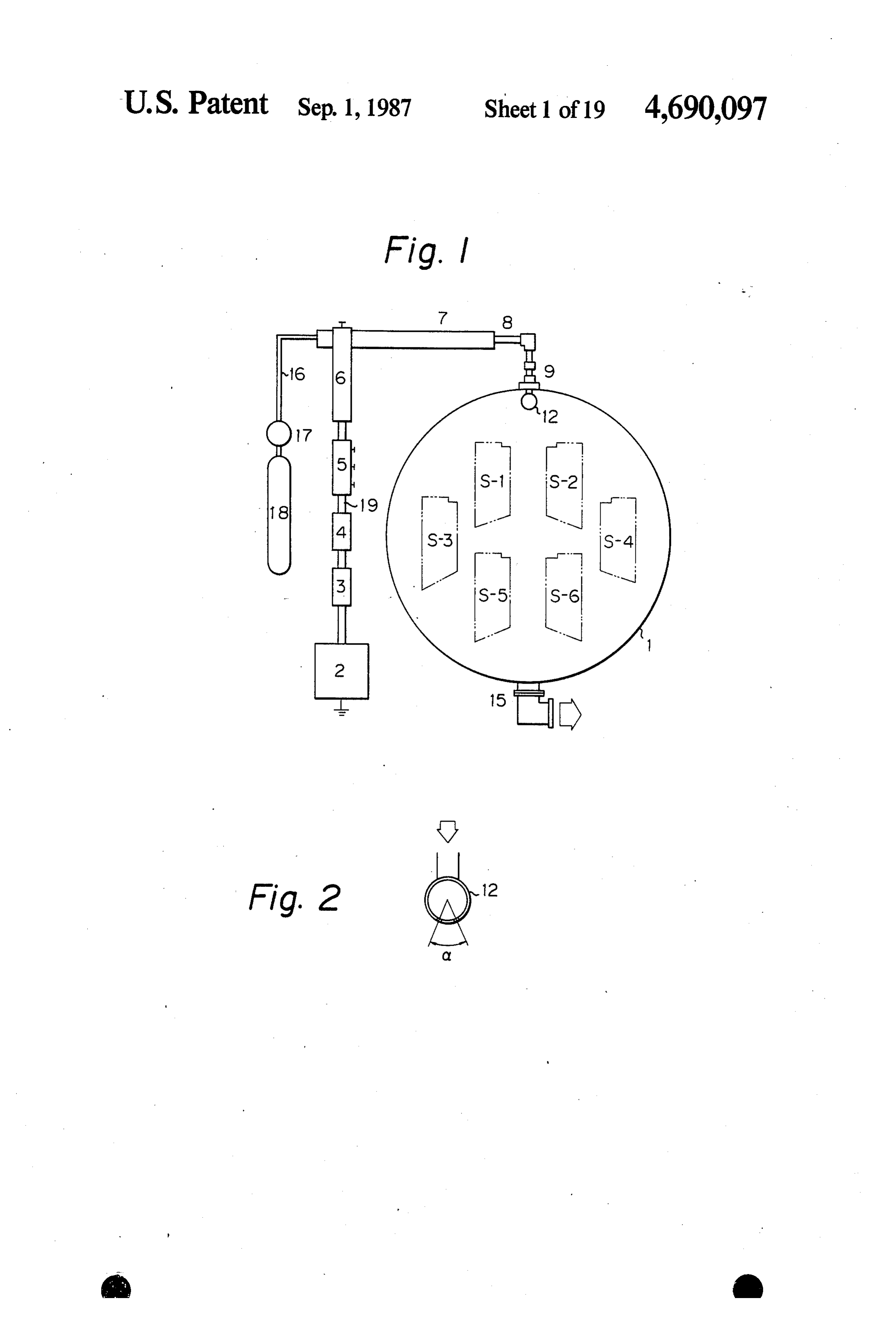
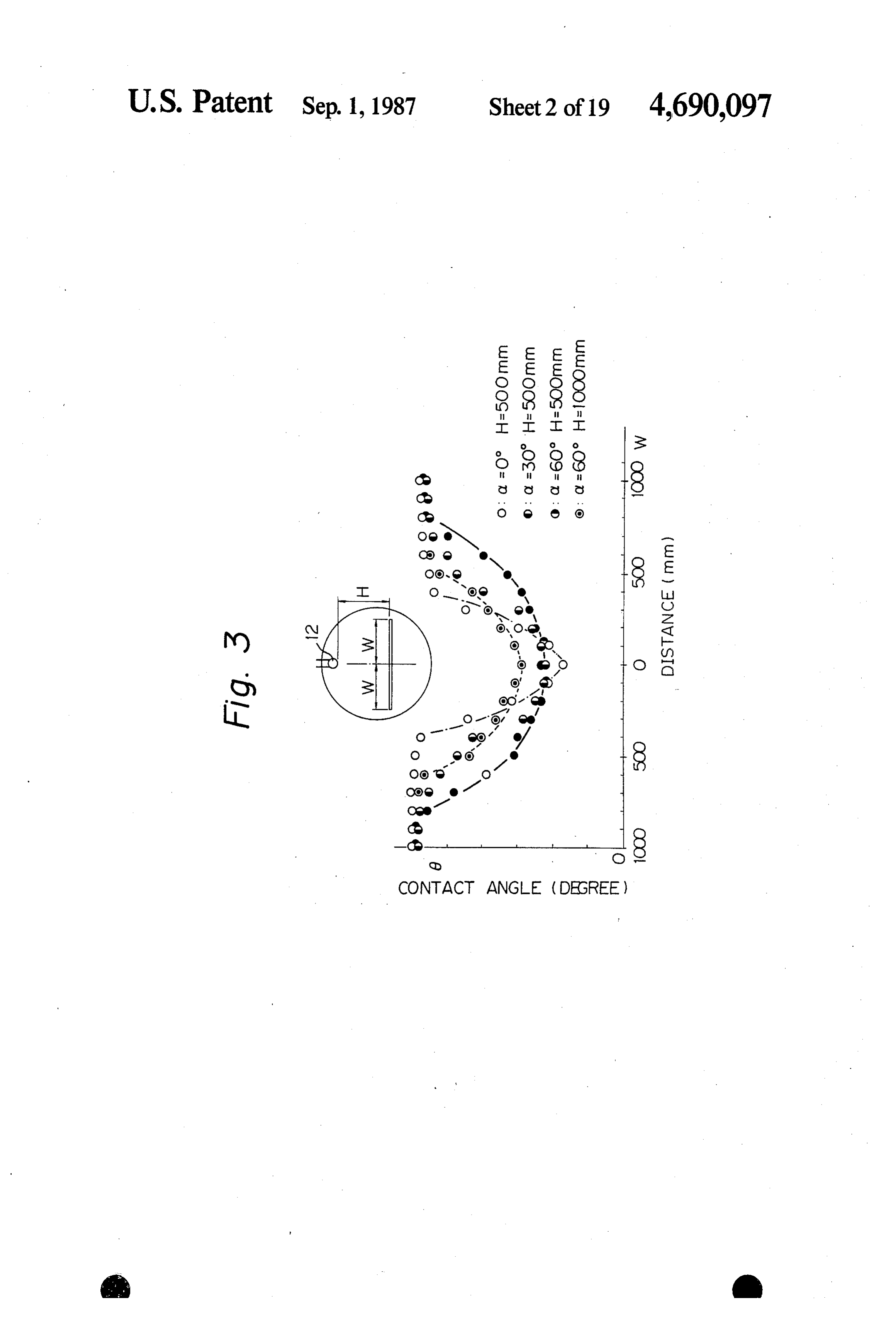
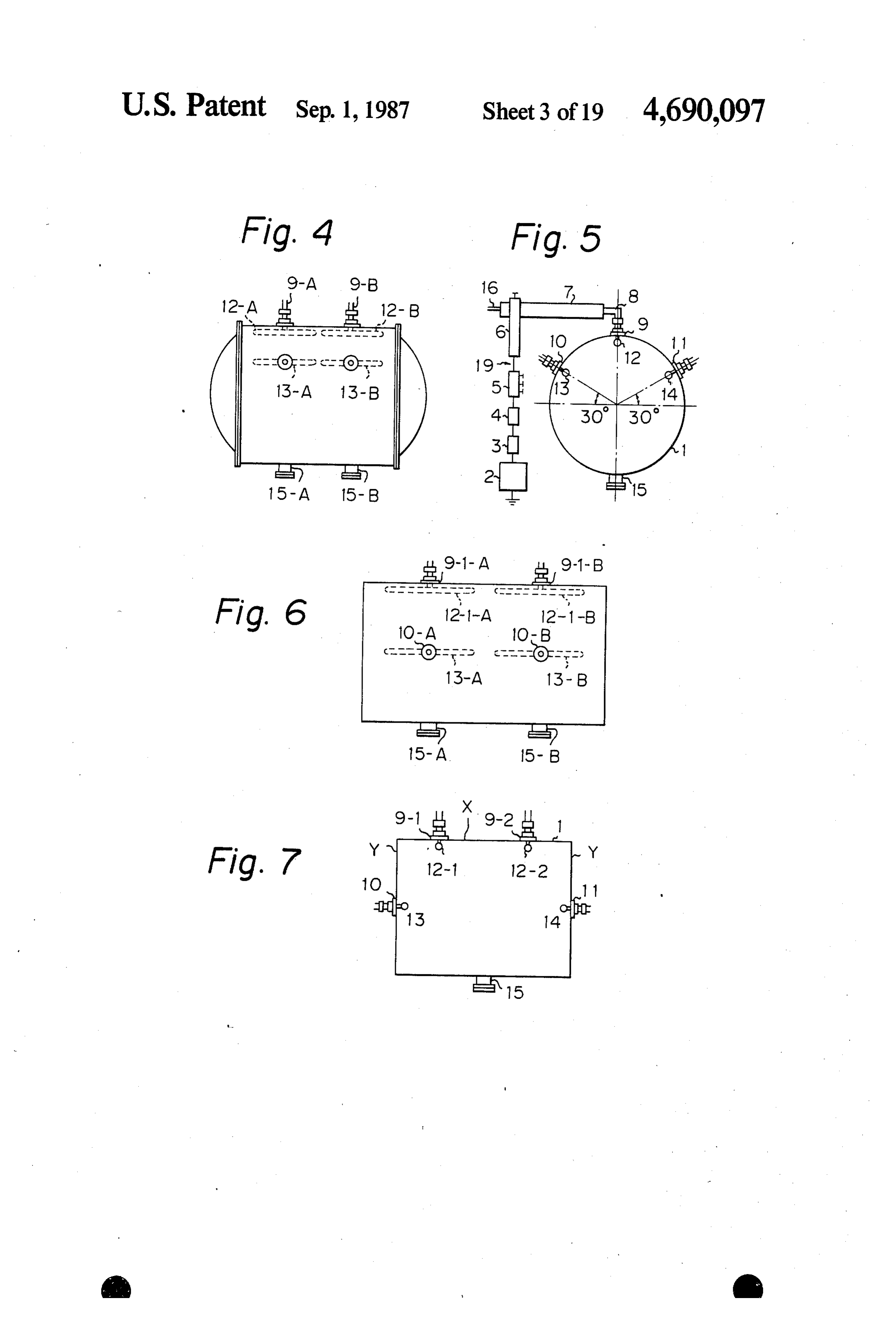
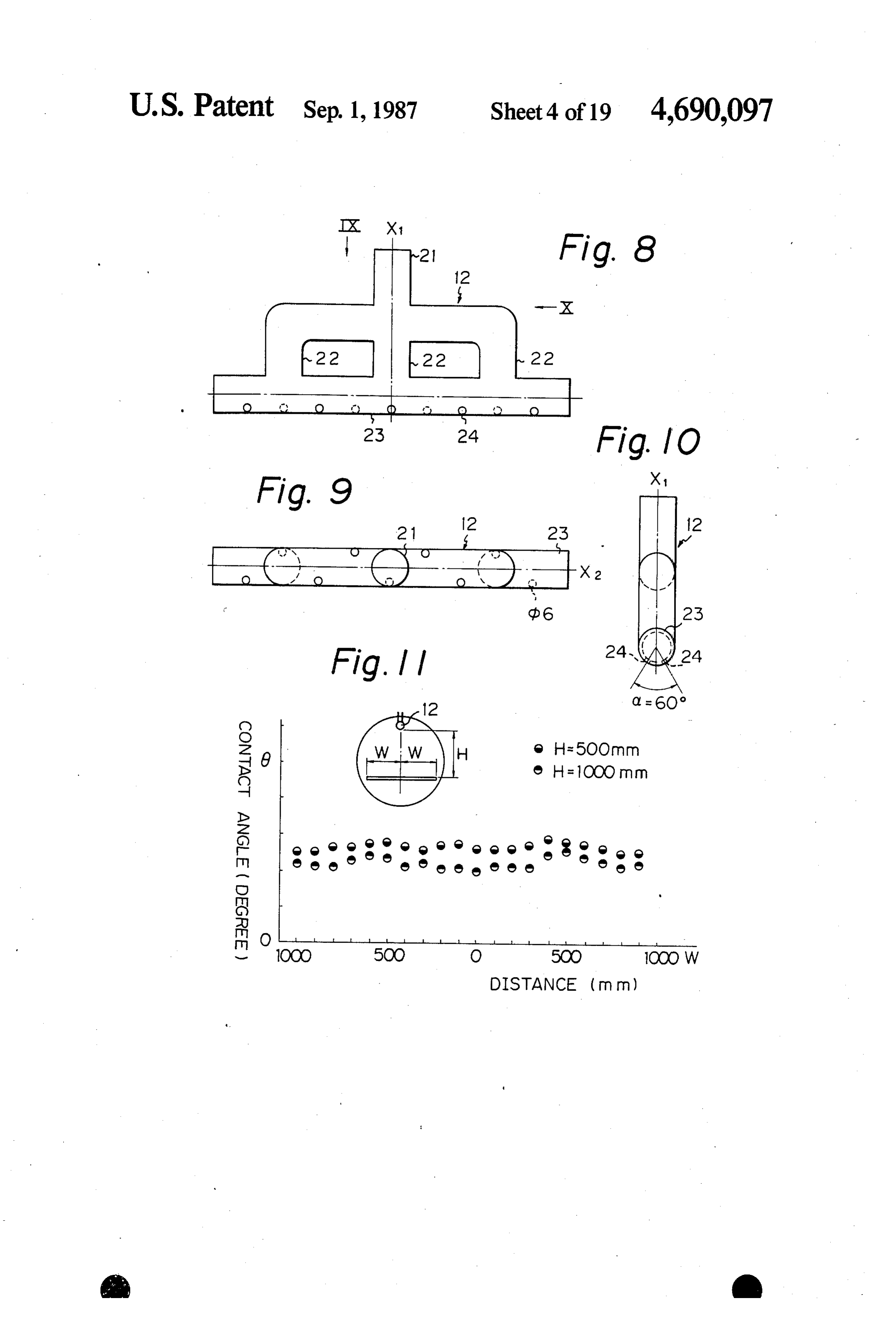
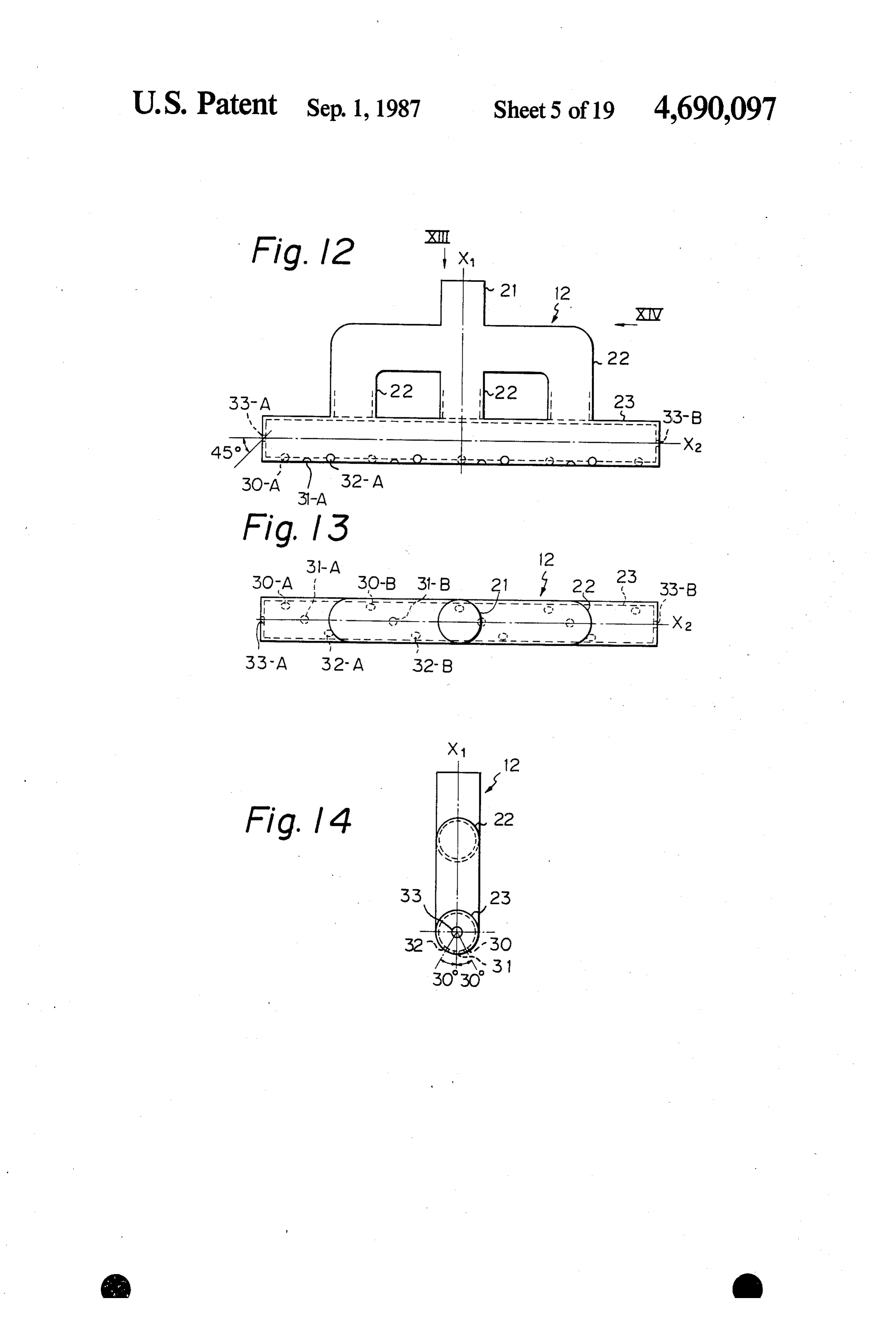
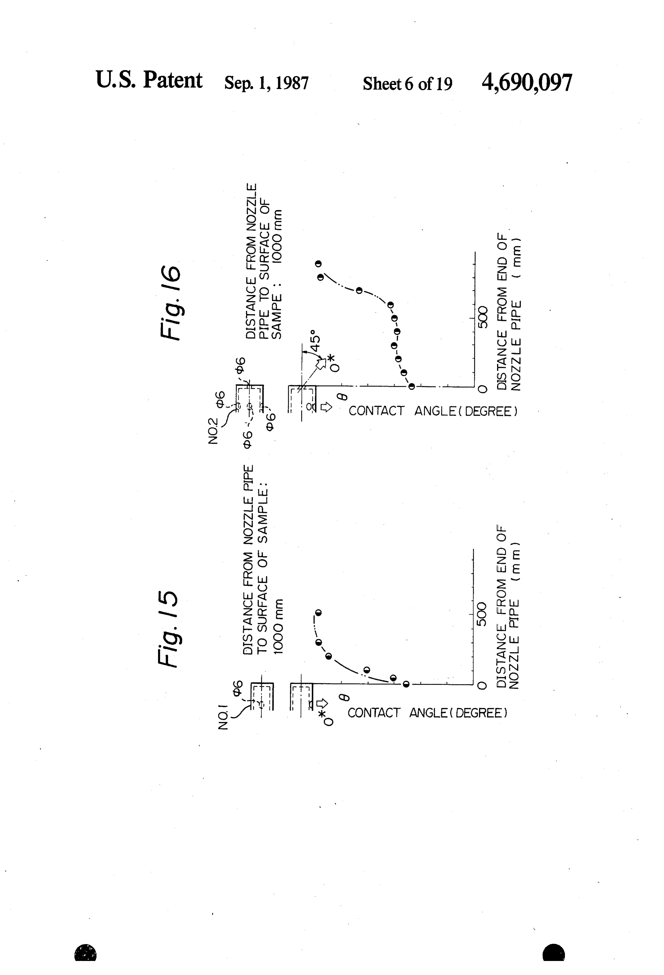
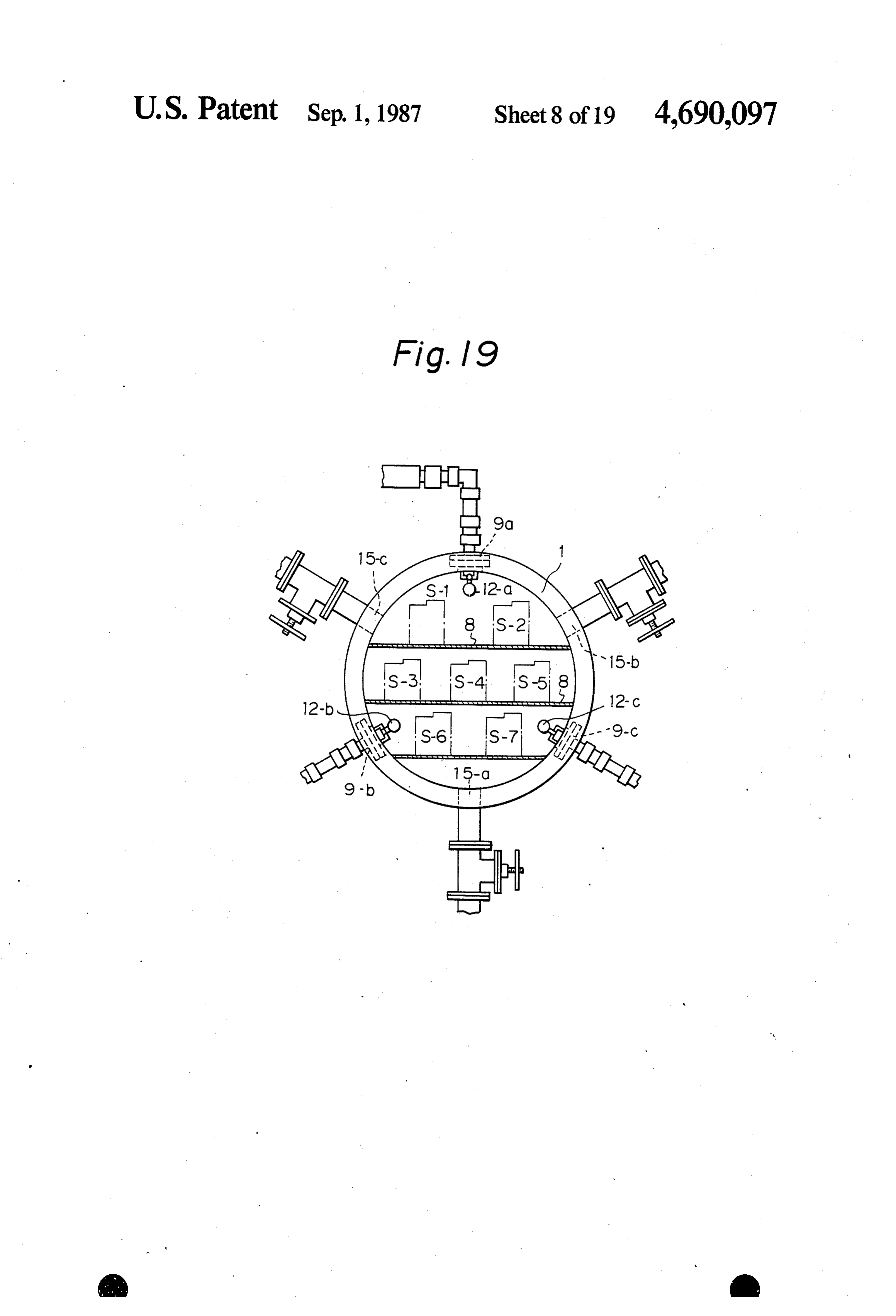
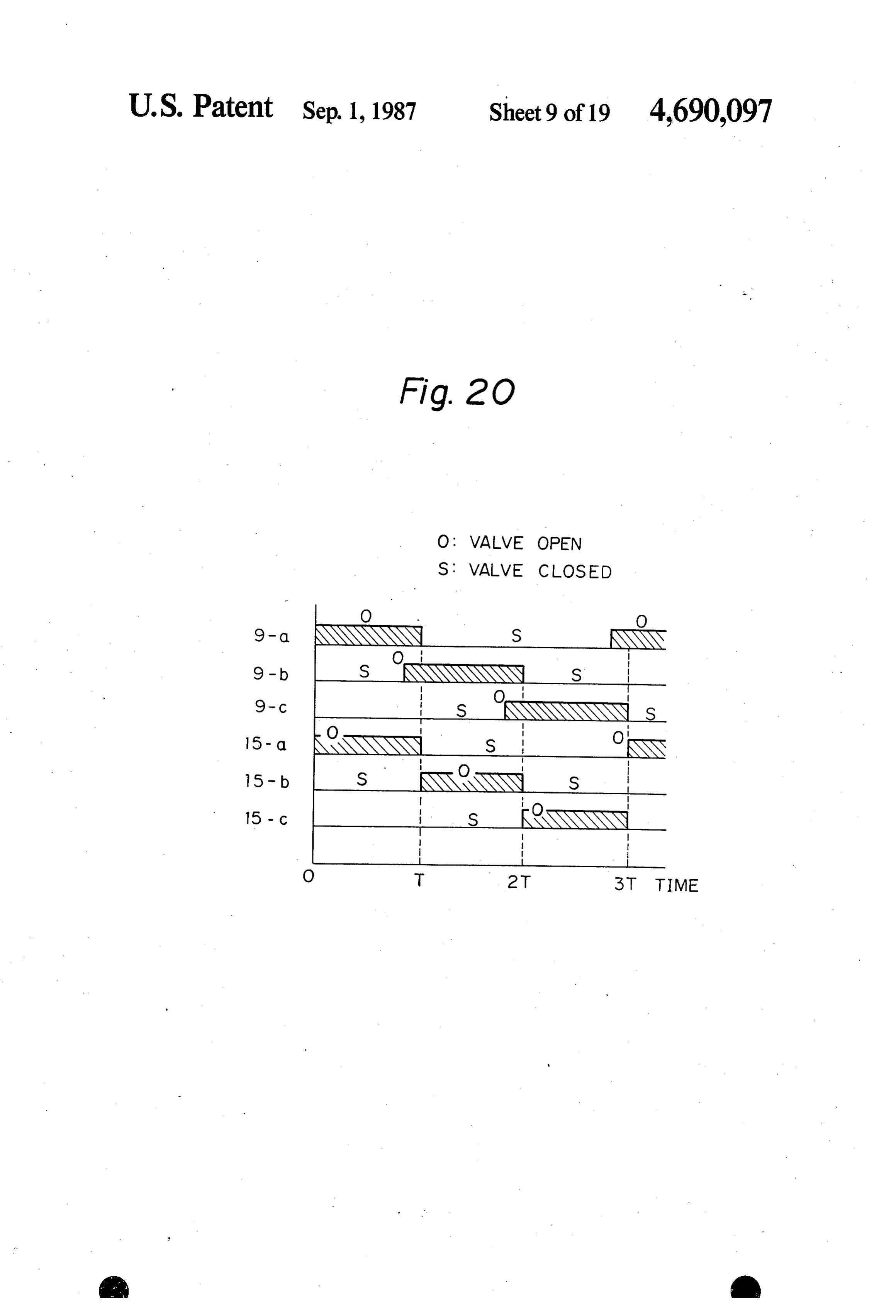
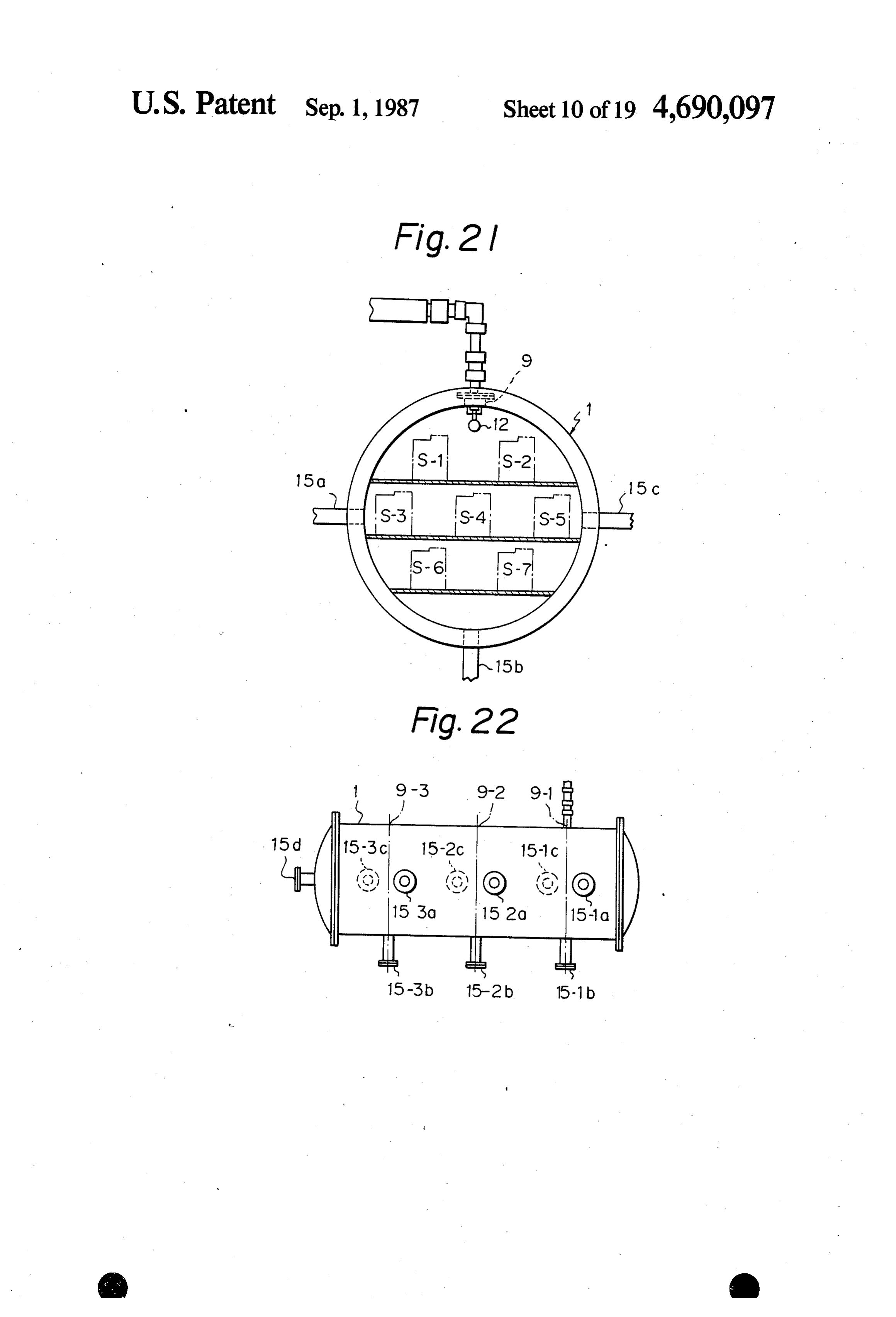
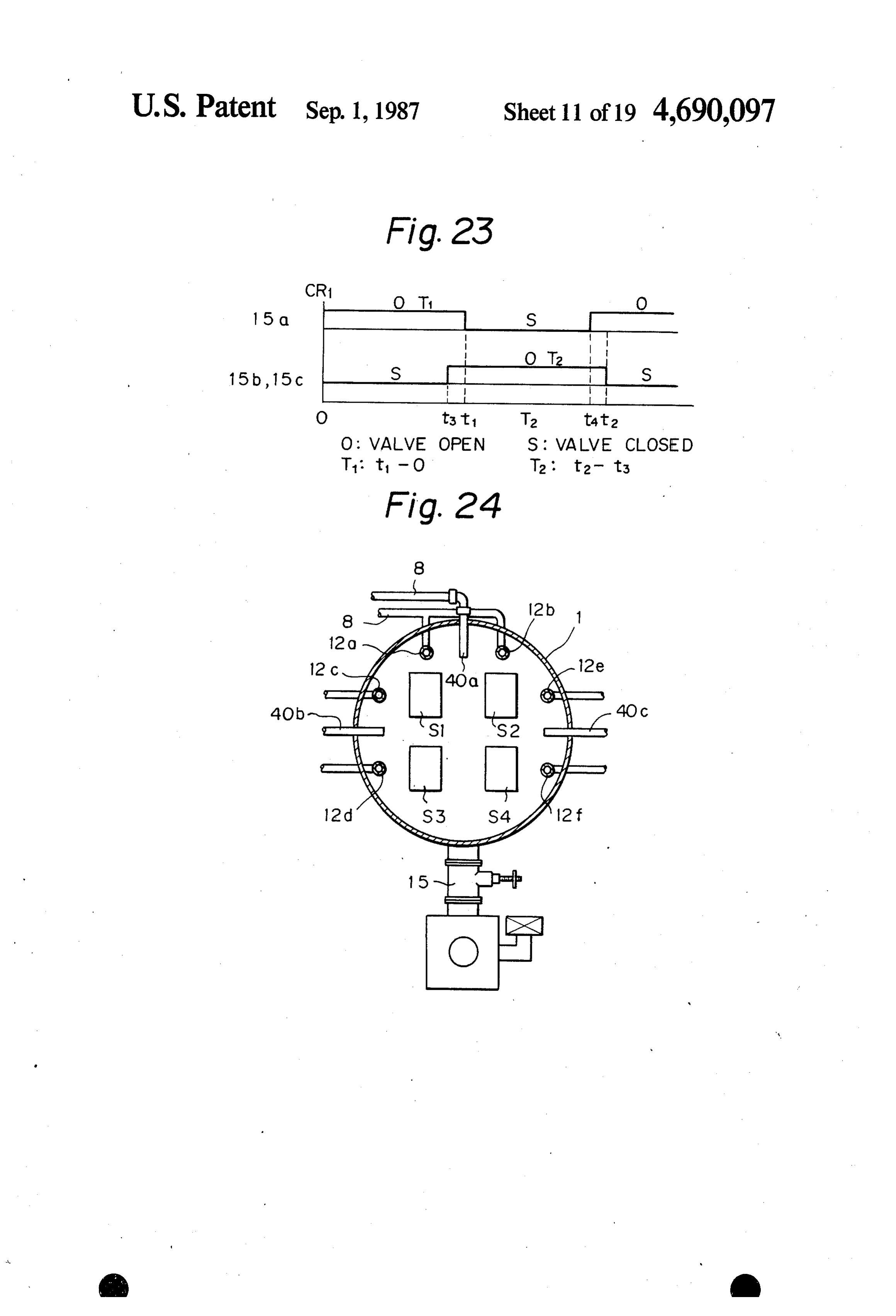
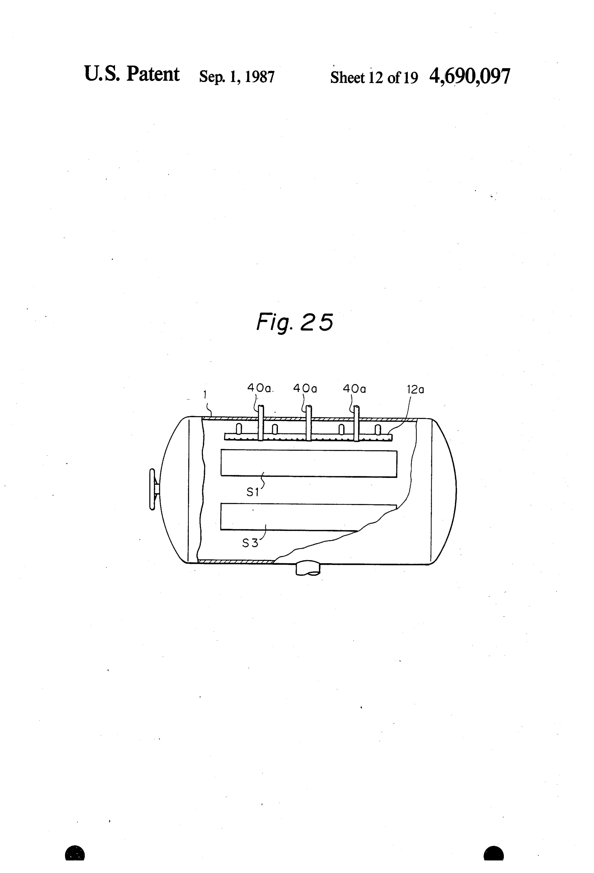
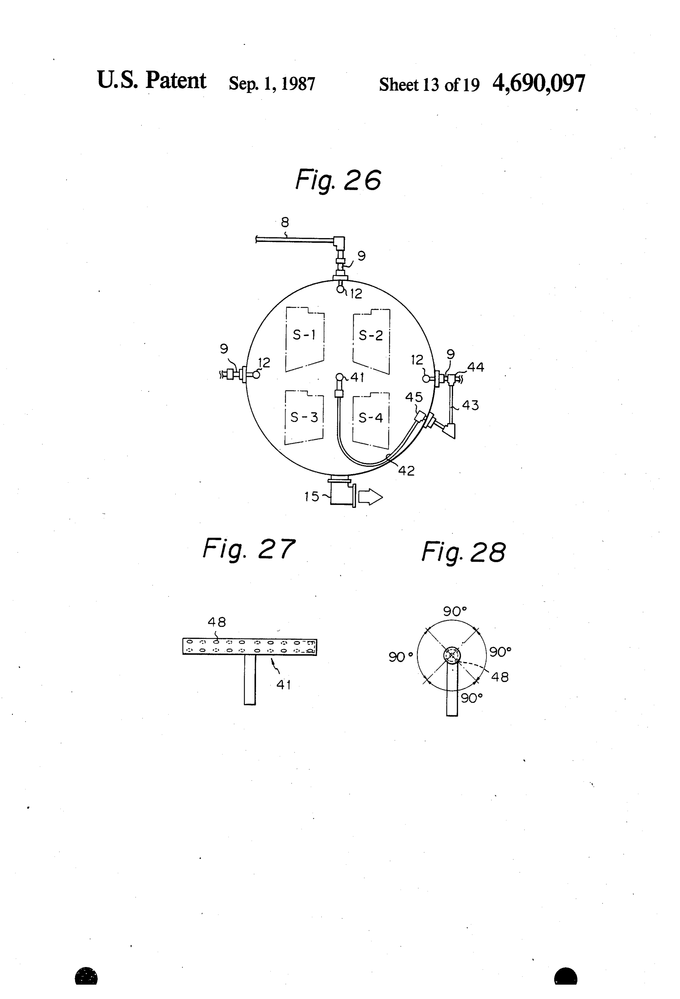
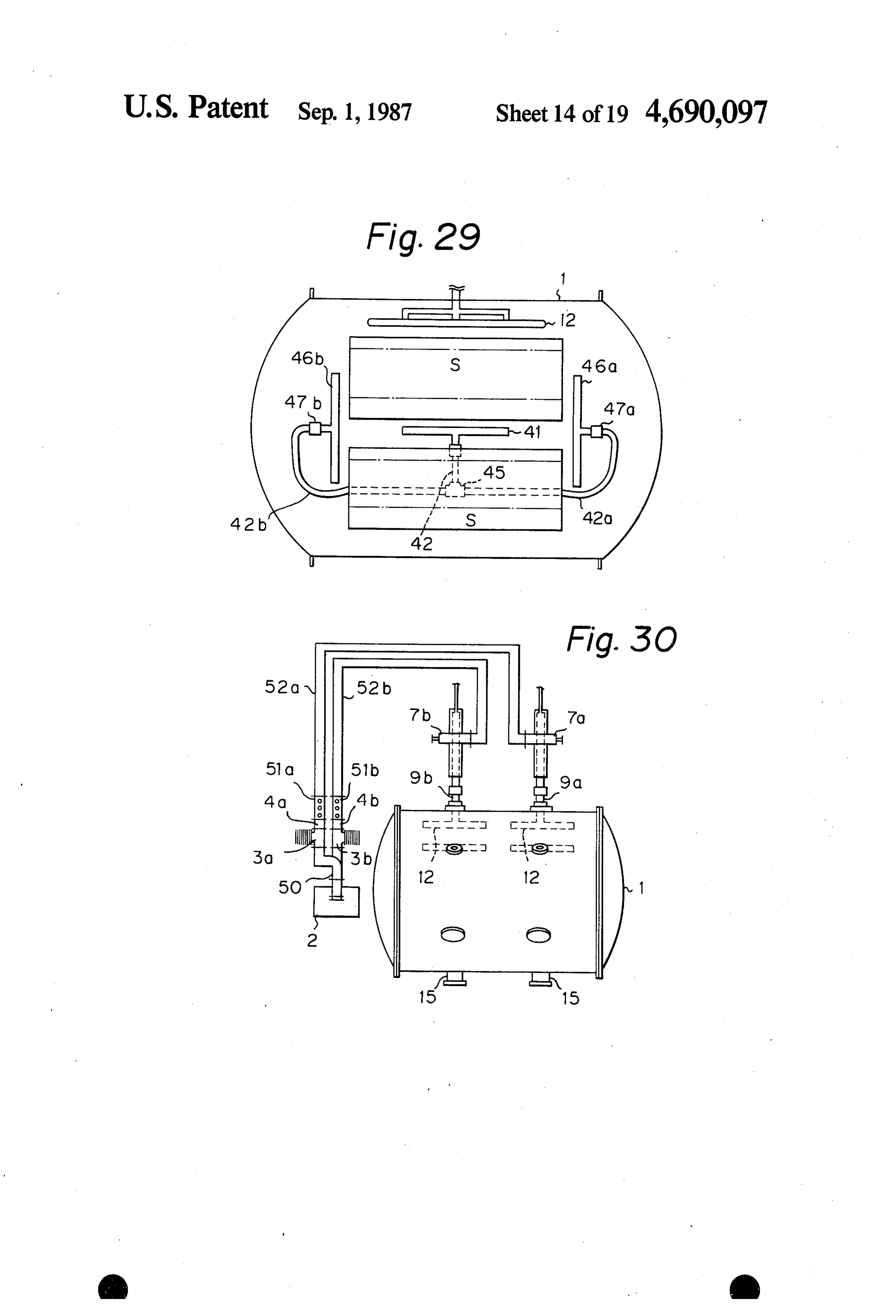
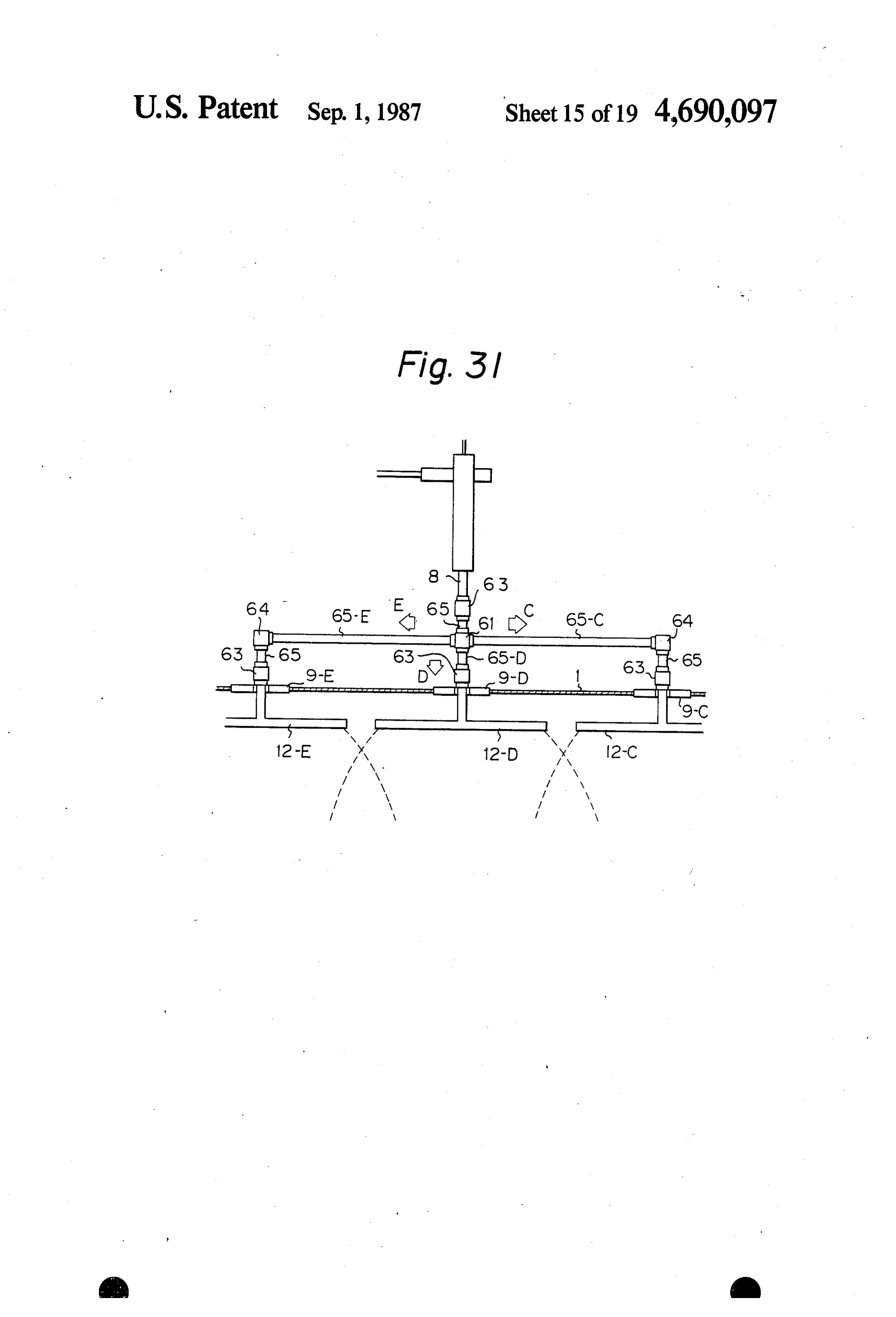
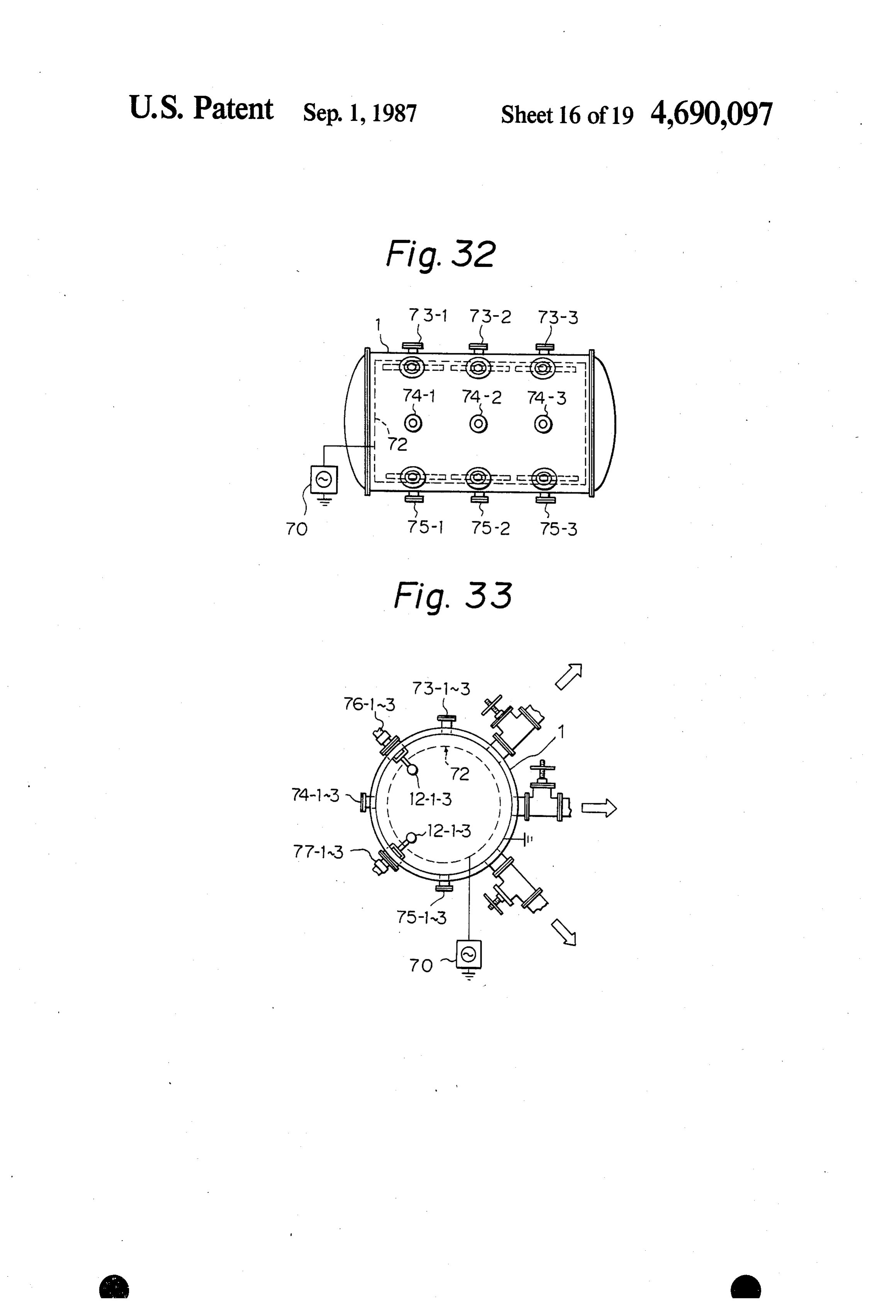
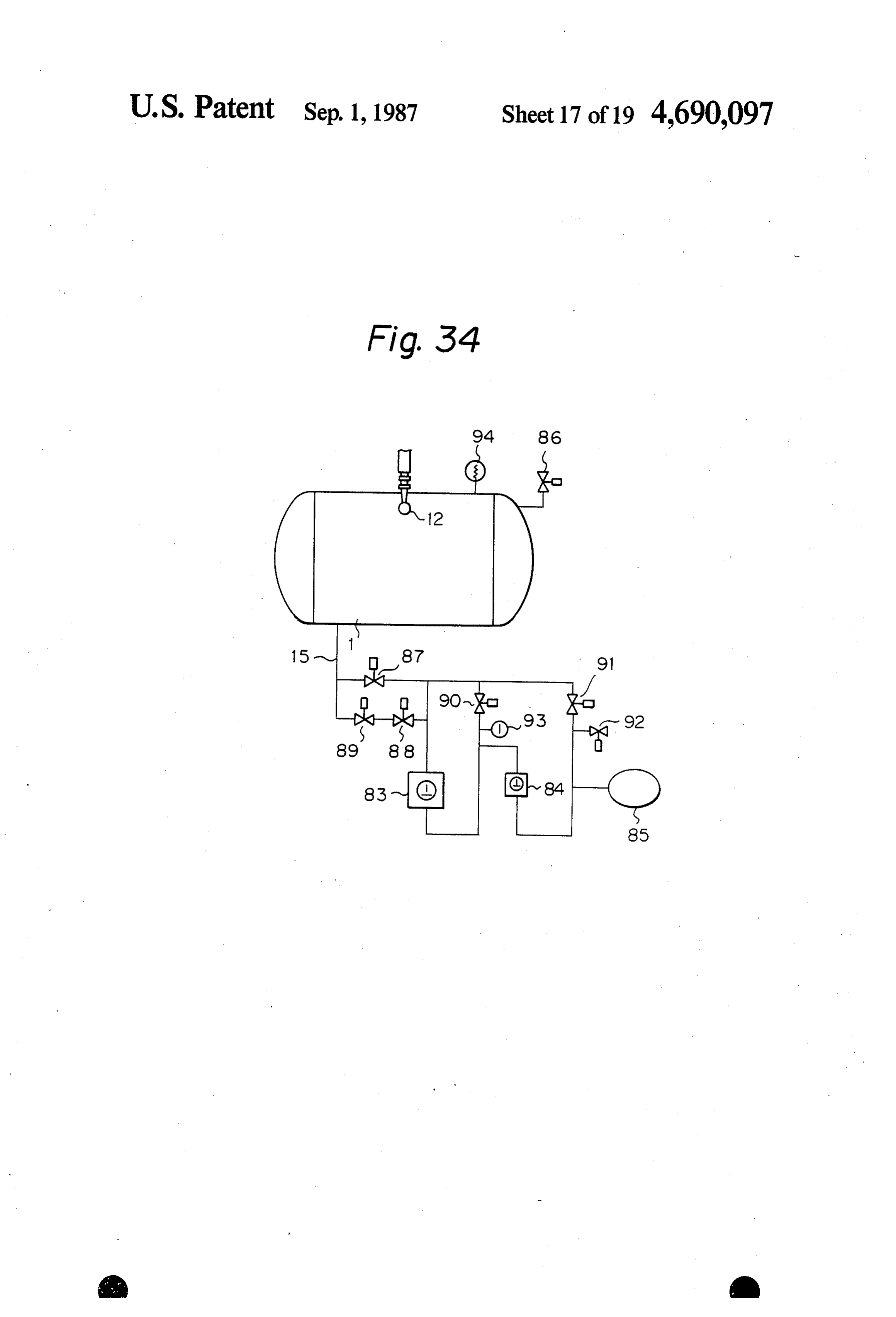
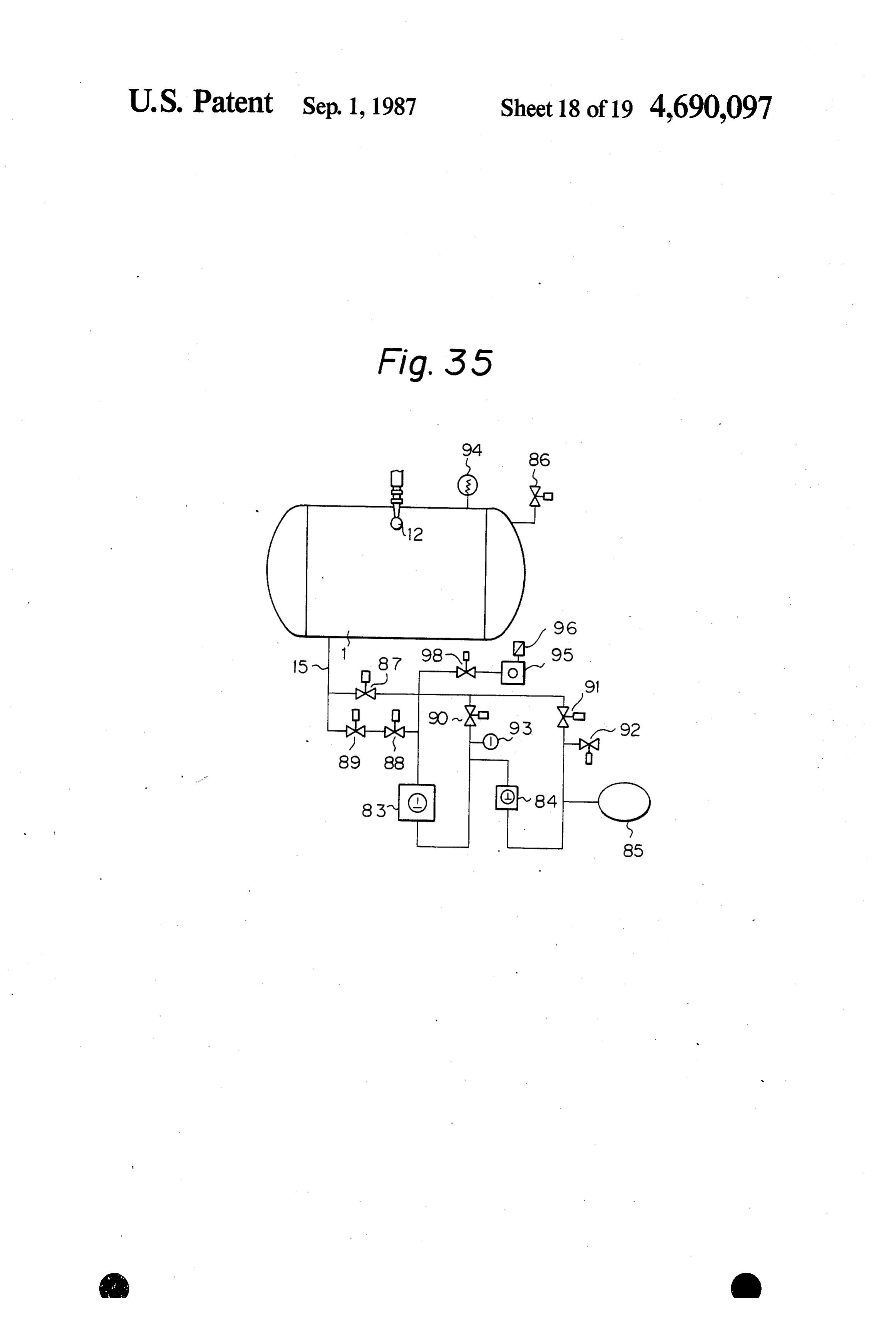
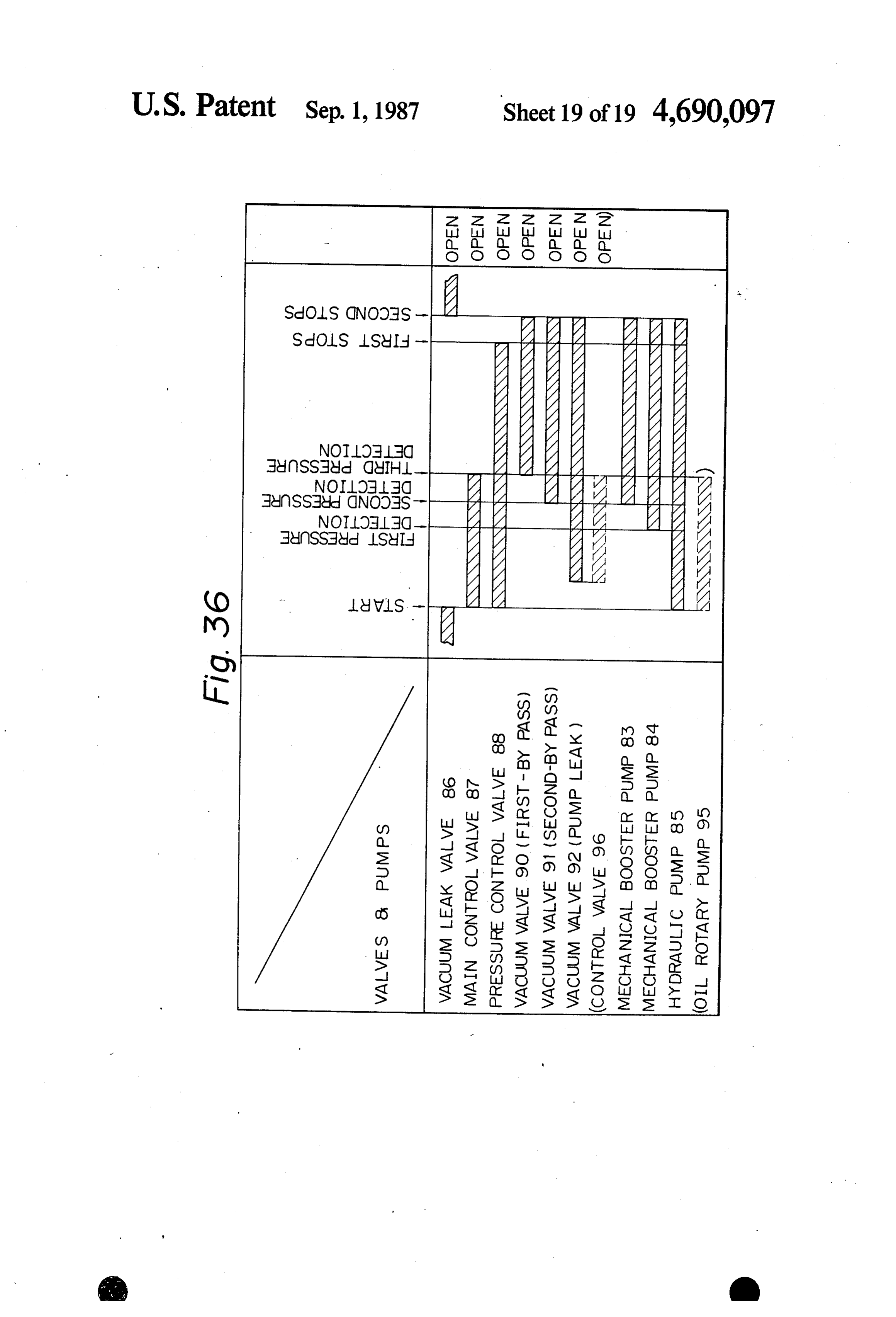
FIG. 17 is a graphical representation of the results of experiments carried out with a comparable glass pipe (a Before describing preferred embodiments of the pres glass pipe provided only with plasma radiating nozzles ent invention in detail, a comparable sample will be 10 described hereunder.
FIG. 25 is a side elevation in section of the essential Procedure of the Preparatory Experiments part of the reaction chamber of the apparatus of FIG. 35 (PPresin sample works) 24; Reaction Chamber
Page 2drawing sheetscan →
Page 3drawing sheetscan →
Page 4drawing sheetscan →
Page 5drawing sheetscan →
Page 6drawing sheetscan →
Page 7drawing sheetscan →
Page 8scan →
Fig. I 7 CONTACT ANGLE (DEGREE)
O (D SAMPLE : 1 OOO mm
DISTANCE FROM CENTER OF NOZZLE PIPE (nm)
Fig. I 8
Contact angle ( degree)
O o 303. o -o
Yo 6 O Vv w ?/ NOZZLE RSTANCEPIPEFOy o SirOOOmm
Ace of sample
DISTANCE FROM CENTER OF NOZZLE PIPE (mrin)
Page 9drawing sheetscan →
Page 10drawing sheetscan →
Page 11drawing sheetscan →
Page 12drawing sheetscan →
Page 13drawing sheetscan →
Page 14drawing sheetscan →
Page 15drawing sheetscan →
Page 16drawing sheetscan →
Page 17drawing sheetscan →
Page 18drawing sheetscan →
Page 19drawing sheetscan →
Page 20drawing sheetscan →
Page 21scan →
A method for plasma treatment for carrying out an
APPARATUS AND METHOD FOR PLASMA other object of this invention is embodied in a method TREATMENT OF RESIN MATERIAL for plasma-treating the surface of works of resin mate rial to be treated within a plasma reaction chamber by
This application is a continuation of application Ser. 5 irradiating the surface with microwave discharge No. 583,270, filed Feb. 4, 1984 now abandoned. plasma, characterized in injecting plasma into the reac FIELD OF THE INVENTION tion chamber from a plurality of positions located adja cent to the inner wall of the reaction chamber, and
This invention relates to an apparatus and method for injecting plasma from each injecting position in a cer the plasma treatment of the surfaces of work made of 10 tain spreading angle along the direction of injection. resin material, such as those made of polypropylene An apparatus for plasma treatment according to this resin (PP) or polyethylene resin (PE), for reforming the invention is designed to irradiate the surfaces of works surfaces thereof. And this invention is particularly ef of resin material to be treated with microwave dis fectively for surface pretreatment when painting com charge plasma within a vacuum reaction chamber paratively large and complicated resin parts. 15 which is in the form of a circular cylinder of 1000 mm
Background of the invention
or more in diameter, a square prism of 1000 mm or more in length of bottom side or in the analogous form and is
It is a recent trend in industries, especially in the characterized in being provided, at a plurality of op automobile industry, for instance, to use resin parts tional positions on the wall of the reaction chamber, which are lightweight and superior in designing flexibil with plasma introducing holes and each plasma intro ity. However, the application of comparatively inex ducing hole being connected to a glass pipe for injecting pensive PP or PE resin to exterior panels of vehicles, angle plasma into the reaction chamber in a certain spreading for instance, entails a problem that the adhesion of paint in an injecting direction. films to the surfaces of resin panels is not so good and 25 Furthermore, an apparatus according to this inven the paint films are likely to peel off the surfaces. Treat tion, for irradiating the surfaces of resin material placed ment of surfaces with plasma has been known as a within a plasma, plasma reaction chamber with microwave means for solving the above-mentioned problem. In discharge comprises glass pipes in the form of a plasma treatment, the surfaces of PP or PE resin parts posed adjacent to and radiating circular cylinder for plasma, each being dis parallel to the wall of the reac are subjected to corona, or glow discharge treatment or 30 tion chamber, and is characterized to radio or microwave discharge treatment to oxidize plasma radiating nozzles formed in by a plurality of (introduction of polar groups) or to etch (improvement enhance the dispersion of the plasma. the glass pipe to of the anchoring effect) the surfaces.
On the other hand, in plasma treatment, it is necessary BRIEF DESCRIPTION OF THE DRAWINGS to evacuate or to reduce the pressure of the reaction 35 FIG. 1 is a schematic sectional view of a plasma chamber in order to enhance the effect of treatment (to treatment apparatus shown for comparison; extend the life of plasma). Accordingly, at the present a batch process is employed in most cases for plasma of FIG. the 2 is a schematic sectional view of the glass pipe apparatus of FIG. 1, as improved for preparatory treatment. experiments;
In applying the batch system of plasma treatment 40 process to the production of automotive parts, namely, theFIG. 3 is a graphical representation of the results of preparatory experiments;
to a mass production process it is required that the FIG. 4 is a side elevation of a first embodiment of a reaction chamber be rapidly evacuated in a short period plasma treatment apparatus according to the present of time and the number of parts which can be subjected invention;
to plasma treatment in one batch cycle be increased. 45 FIG. 5 is a schematic sectional view of the apparatus However, the conventional apparatus for plasma treat of FIG. 4;
ment has a problem that the parts are plasma-treated FIG. 6 is a side elevation of a second embodiment of differently among the parts as well as within each part a plasma treatment apparatus according to the present depending on the disposition of the parts in the reaction invention;
chamber, since automotive parts are large and compli 50 FIG. 7 is a schematic sectional view of the apparatus cated in configuration. of FIG. 6;
SUMMARY OF THE INVENTION FIG. 8 is a front elevation of a glass pipe employed in the apparatus of the present invention;
This invention is to provide a method and apparatus FIG. 9 is a view taken in the direction of the arrow for plasma treatment, which method and apparatus are 55 IX in FIG.8;
capable of solving the above-mentioned problems and FIG. 10 is a view taken in the direction of the arrow of uniformly plasma-treating numerous comparatively X in FIG. 8;
large parts of complicated configuration at the same FIG. 11 is a graphical representation of the results of time. experimental plasma treatment according to the present Accordingly, it is a primary object of this invention 60 invention;
to provide a method and an apparatus for plasma treat FIG. 12 is a front elevation of a glass pipe employed ment, which method and apparatus are capable of estab in a further embodiment of the present invention; lishing the uniform distribution of plasma density within FIG. 13 is a view taken in the direction of the arrow a reaction chamber so that a plurality of parts placed in XIII in FIG. 12;
the reaction chamber are treated to the same extent 65 FIG. 14 is a view taken in the direction of the arrow regardless of the disposition and so that the individual XIV in FIG. 12;
parts are treated uniformly over the entire surfaces FIG. 15 is a graphical representation of the results of thereof regardless of the configuration thereof. experiments carried out with a comparable glass pipe (a 22 glass pipe provided with no plasma radiating nozzle in FIG. 36 is a timing chart of the evacuating process the end walls); for carrying out the method of the present invention FIG. 16 is a graphical representation of the results of employing the plasma treatment apparatus of FIGS. 34 experiments carried out with a glass pipe embodying (or 35).
the present invention (a glass pipe provided with plasma 5 DETAILED DESCRIPTION OF THE radiating nozzles in the end walls); PREFERRED EMBODIMENTS
FIG. 17 is a graphical representation of the results of experiments carried out with a comparable glass pipe (a Before describing preferred embodiments of the pres glass pipe provided only with plasma radiating nozzles ent invention in detail, a comparable sample will be 10 described hereunder.
FIG. 18 is a graphical representation of the results of FIG. 1 is a schematic illustration of a microwave experiments carried out with a glass pipe embodying discharge plasma treatment apparatus of a comparable the present invention (a glass pipe provided with plasma example. Resin parts used for motor vehicles were sub radiating nozzles 30, 31 and 32); jected to surface treatment in this plasma treatment FIG. 19 is a schematic sectional view of a further 15 apparatus. The degree of surface was not uniform, embodiment of a plasma treatment apparatus according among the parts as well as among the positions within to the present invention; each part, due to the large size and the complicated FIG. 20 is a timing chart showing the opening and configuration of those parts.
closing timings of plasma introducing ports and exhaust 20 In FIG. 1, there are shown a reaction chamber 1, a ports respectively; microwave oscillator 2, an isolator 3 (Toshiba Corp.), a FIG. 21 is a schematic sectional view of a still further power monitor 4 (Toshiba Corp.), a three-stab tuner 5 embodiment of a plasma treatment apparatus according (Toshiba Corp.), a plasma generating furnace 6, a to the present invention; plasma generating pipe 7, a quartz pipe 8, a plasma FIG.22 is a general longitudinal sectional view of the 25 introducing port 9, a plasma-irradiating pipe 12, a dis plasma treatment apparatus of FIG. 21; charge port 15 for evacuating the reaction chamber, a FIG. 23 is a timing chart showing the opening and gas supply conduit 16, a flow meter 17, a gas bomb 18, closing timings of the exhaust ports of the apparatus of a waveguide 19 and sample works S1 to S6. FIG. 21; Preparatory experiments were carried out in the fol FIG. 24 is an elevational view in section of the essen lowing manner to acquire data for solving the above tial part of a plasma treatment apparatus provided with mentioned problems residing in the microwave dis shower pipes and straight pipes, embodying the present charge plasma treatment apparatus of a comparable invention; example in FIG. 1
FIG. 25 is a side elevation in section of the essential Procedure of the Preparatory Experiments part of the reaction chamber of the apparatus of FIG. 35 (PPresin sample works) 24; Reaction Chamber
FIG. 26 is a schematic illustration of a plama treat Cylindrical chamber: 2000 mm diameter X2000 mm ment apparatus provided with fixed shower pipe and length movable shower pipe adapted to be moved to an op Conditions of Treatment) tional position; 40 Frequency of microwave: 2450 MHz FIGS. 27 and 28 are detail views of a shower pipe Output capacity: 500 W connected to a flexible tube; Degree of vacuum: 0.5 Torr FIG. 29 is a schematic illustration of a further plasma Working gas (flow rate): Oxygen gas (5000 cc/min) treatment apparatus embodying the present invention, Duration of treatment: 30 sec provided with a fixed shower pipe and movable shower 45 Plasma-Irradiating pipe pipes; Plasma injection angle a of the glass pipe 12:0', 30', FIG. 30 is a schematic illustration of a plasma treat 60 (refer to FIGS. 2 and 11) ment apparatus embodying the present invention, in Disposition of Sample Works which the microwave is branched into a plurality of The sample works were so located that the distance beams and introduced into the reaction chamber from a 50 H between the plasma injection nozzle made of the plurality of positions; glass pipe 12 and the surfaces of the sample works, FIG. 31 is a detail view of a branching unit for along the bisector of the angle a, was 500 mm or branching, outside the reaction chamber, the plasma 1000 mm, as illustrated in FIG. 11. The contact into a plurality of streams to introduce the plasma from angle of the plasma-treated surface of the sample a plurality of positions; 55 works was measured, at positions on opposite sides FIG. 32 is a side elevation of a plasma treatment and at a distance W (W=0 to 1000 mm), with re apparatus employing both radio wave discharge plasma spect to the point from the distance H of the inter and microwave discharge plasma; section of the bisector of the plasma injection an FIG. 33 is a sectional view of the apparatus of FIG. gle. Measured results are shown in FIG. 3. 32; 60 Contact Angle Measuring Method FIG. 34 is a schematic illustration of a plasma treat Demineralized water of 5 u1 in quantity was dropped ment apparatus in which the reaction chamber is evacu on the plasma-treated surface of the PP resin sam ated by the combined action of a hydraulic pump and a ple works. A contact angle measuring instrument mechanical booster pump; (Kyowa Kagaku, Model: CA-A) was used for the FIG. 35 is a schematic illustration of a plasma treat 65 measurement of the contact angle. The ambient air ment apparatus in which the reaction chamber is evacu conditions were 20 C. and 50to 60% RH. ated by the combined action of a hydraulic pump, an oil The results of the preparatory experiments (FIG. 3) rotary pump and a mechanical booster pump; and showed that:
Page 23scan →
(1) The life of the plasma introduced into the reaction indicated by X as illustrated in FIG. 7, at an interval of chamber 1 is dependent on the distance between the 1000 mm or less, for example, 900 mm. The other con plasma injection nozzle of the glass pipe 12 and the stitution and the functions of this second embodiment sample work; and are the same as the first embodiment. (2) The diffusion of the plasma introduced into the FIGS. 8 to 10 show plasma-irradiating pipes 12-, 13 reaction chamber 1 is dependent on the position (and/or and 14-A and B (first embodiment) or 12-1-, 12-2-A and angle a) of the plasma injection nozzle of the glass pipe B, 13-, 14-A and B (second embodiment) connected to 12. the plasma introducing ports 9-, 10-, 11-A and B (first Although not shown in FIG. 3, in addition to the embodiment) or 9-1-, 9-2-A and B, 10-, 11-A and B facts explained in Paragraphs 1) and 2) described above, 10 (second embodiment) respectively. Desirably, the plas it was found that the plasma treatment was affected by ma-irradiating pipe 20 is formed of glass or quartz. The the screening effect of the work affects. These are plasma-irradiating pipe 20 is joined at a base 21 thereof deemed to be attributable to the irregular distribution of to the plasma introducing port (9, 10 or 11). A manifold the plasma density within the reaction chamber. 22 extends from the base 21 and a cylindrical spraying FIGS. 4 and 5 illustrate a first embodiment of a 5 head 23 extends from the manifold 22. The spraying plasma treatment apparatus according to the present head 23 is formed so as to extend perpendicularly to and invention. In this embodiment, the reaction chamber 1 is symmetrically with respect to the center axis X1 of the of a circular cylinder. Referring to FIGS. 4 and 5, there corresponding plasma introducing port. The opposite are shown a cylindrical reaction chamber 1 of 1000 mm ends of the spraying head 23 are closed. A plurality of or more in diameter, a microwave oscillator 2, an isola 20 plasma injection nozzles 24 of, for example, 6 mm in tor 3 (Toshiba Corp.), a power monitor 4 (Toshiba diameter are provided in the lower side of the spraying Corp.), a three-stab tuner 5 (Toshiba Corp.), a plasma head 23 at fixed intervals along the longitudinal direc generating furnace 6, a plasma generating tube 7, a tion. The plasma injection nozzles 24 are staggered with quartz tube 8, plasma introducing ports 9 (9-A, 9-B), 10 respect to the center axis X2 of the spraying head 23 as and 11, plasma- irradiating pipes 12 (12-A, 12-B), 13 25 viewed in FIG. 9, so that the adjacent plasma injection (13-A, 13-B) and 14, exhaust ports 15 (15-A, 15-B) for nozzles are disposed on opposite sides of a plane defined evacuating the reaction chamber 1, a gas supply conduit by the center axes X and X2 as viewed in FIG. 10 and 16 and a waveguide 19. The microwave generated by at an angular interval of 60 (at an angular position of the oscillator 2 is guided through the isolator 3, the 30 on each side of the plane defined by the center axes power monitor 4 and the three-stab tuner 5 to the X1 and X2) plasma generating furnace 6 by the waveguide 19. On FIG. 11 show measured results obtained by the ex the other hand, a gas to be converted into a plasma is perimental plasma treatment of works (PPresin works) supplied through the conduit 16 to the plasma generat by using the apparatus of the first embodiment (FIGS. 4 ing pipe 7. The plasma generated in the plasma generat and 5) employing the plasma-irradiating pipes of FIGS. ing pipe 7 and the plasma generating tube 7 is sent to the 35 8 to 10. In this experimental plasma treatment, the plas plasma introducing ports 9-A, 9-B, 10-A, 10-B, 11-A ma-irradiating pipes were disposed so that the longitudi and 11-B. In the first embodiment, the three pairs of the nal axes of the plamsa-irradiating pipes extend along the plasma introducing ports 9, 10 and 11 are arranged on longitudinal axis of the cylindrical reaction chamber 1 the three generatrices of the reaction chamber 1 which as illustrated in FIG. 4. The size of the reaction cham are separate from each other by an angular interval of 40 ber, the conditions of treatment and the contact angle 60 respectively. The plasma sent to the plasma intro measuring method are the same as those of the prepara ducing ports is injected into the reaction chamber 1 by tory experiments. The distance H between the plasma the plasma-irradiating pipes 12-A, 12-B, 13-A, 13-B, injection nozzle and the surface of the sample works 14-A and 14-B connected to the plasma introducing were 1000 mm and 500 mm (H is the distance between ports 9-A, 9-B, 10-A, 10-B, 11-A and 11-B respectively. 45 the plasma-irradiating pipe 12 shown in FIG. 5 and the The details of plasma injection nozzles formed in the sample works). Contact angle was measured for the plasma-irradiating pipes are illustrated in FIGS. 8 to 10. surface of the sample works within a range of W=0 to Since the reaction chamber 1 needs to be evacuated to W=1000 mm (The definition of W in this experiment is a degree of vacuum of approximately 1.0 to 0.05 Torr the same as in the preparatory experiments). Other con for plasma treatment, the reaction chamber 1 is evacu 50 ditions of experiments were the same as the preparatory ated continuously by a vacuum pump, not shown, con experiments mentioned before.
nected through pipes, not shown, to the exhaust ports It is obvious from the results of the experiments as 15. shown in FIG. 11 that the present invention is capable FIGS. 6 and 7 show a second embodiment of a of establishing uniform distribution of plasma density plasma treatment apparatus according to the present 55 within the reaction chamber, and capable of plasma invention. In this embodiment, the reaction chamber 1 is treating many comparatively large works of compli formed in the form of a rectangular prism having sides cated configuration, simultaneously and uniformly, re each of 1000 mm or more in length. Same or corre gardless of the location of the works, and also capable sponding parts are indicated by same or corresponding of eliminating irregular plasma treatment within each reference numerals through the first and the second 60 work attributable to the configuration. embodiments. The size of the reaction chamber 1 in the FIGS. 12 to 14 show a second embodiment of a plas form of a rectangular prism is, for example, that as ma-irradiating pipe according to the present invention. indicated by the X in FIG. 7 is 2500 mm which is the . The plasma-irradiating pipe is joined coaxially at a base width of a wall provided with plasma introducing ports 21 to the plasma introducing port 9, 10 or 11 (FIGS. 4 9-1 and 9-2;Y, which is also indicated in FIG. 7, is 1800 65 and 5). A manifold 22 extends from the base 21 and a mm. It denotes the width of walls provided with plasma cylindrical spraying head ("pipe' in a narrow sense) 23 introducing ports 10 and 11. A plurality of the plasma extends from the manifold 22. The plasma introducing introducing ports 9-1 and 9-2 are arranged on the wall ports 9, 10 and 11 are formed in the wall of the reaction 24 chamber 1 as illustrated in FIGS. 4 and 5. The center FIG. 17 shows experimental results of plasma treat axis X1 of each plasma introducing port extends perpen ment, in which the plasma-irradiating pipe (No. 3) hav dicularly to the wall of the reaction chamber 1 (FIG. 4) ing the plasma injection nozzles 31 formed in the plasma and intersects the longitudinal center axis of the reac spraying head within a plane including the center axes tion chamber 1 (FIG. 5). The spraying head 23 is dis X1 and X2 (FIG. 14) was employed for comparison. posed in parallel to the longitudinal axis of the reaction FIG. 18 shows experimental results of plasma treat chamber 1, with its center axis X2 extending perpendic ment, in which the above-mentioned plasma-irradiating ularly to the center axis X of the corresponding plasma pipe (No. 4) embodying the present invention, having introducing port. The spraying head 23 extends for the plasma injection nozzles 31 formed in a plane in equal lengths on both sides with respect to the center 10 cluding the center axes X and X2 (FIG. 14) and plasma axis X1 of the corresponding plasma introducing port. injection nozzles 30 and 32 formed in the same plasma That is, the cylindrical spraying head 23 extends adja spraying head outside the plane including the plasma cent to and in parallel to the wall of the reaction cham injection nozzles 31. In either experiment of plasma ber. treatment, the surface of a work was placed 1000 mm A plurality of plasma injecting nozzles 30 to 33 are 15 apart from the plasma-irradiating pipe, and contact formed in the cylindrical spraying head 23. The diame angle was measured at measuring points on a line ex ter of the plasma injection nozzle is, for example, 6 mm. tending perpendicularly to the longitudinal direction of The plasma injection nozzles 31-A, 31-B, ... are formed the pipe. In FIGS. 17 and 18, the abscissa represents the in the bottom of the cylindrical spraying head 23 as distance (mm) from the point of center 1000 mm apart viewed in FIG. 14 (in the portion of the cylindrical 20 from the plasma spraying head to the measuring point, spraying head 23 extending farthest from the adjacent while the ordinate represents measured contact angle. wall of the reaction chamber 1) along the longitudinal As is evident from the comparative examination of direction of the cylindrical spraying head 23 at a fixed FIGS. 17 and 18, the provision of the plasma injection interval (approximately 20 mm). The plasma injection nozzles 30, 31 and 32 in an arrangement as illustrated in nozzles 30-A, 30-B, ... and the plasma injection nozzles 25 FIG. 14 uniformizes the distribution of plasma density 32-A, 32-B, . . . are disposed along the longitudinal within the reaction chamber.
direction of the spraying head 23 on opposite sides, Furthermore, the inventors of this invention had respectively, of a plane including the center axis X1 and made a study to improve the plasma transporting pipe the plasma injection nozzles 31-A, 31-B, . . . and apart and the plasma-irradiating pipe of a plasma treatment from the plasma injection nozzles 31-A, 31-B, ... by an 30 apparatus based on microwave discharge system and angular interval of 7.5 to 45, preferably, 15 to 30', for found that those pipes could be made of a stainless steel. example, 30', at a fixed longitudinal interval as illus Such a plasma treatment apparatus is constituted to trated in FIGS. 13 and 14. It is desirable to dispose the transport the plasma generated in a plasma generating plasma injection nozzles 30-A, 30-B, ..., 31-A, 31-B, . pipe, for example, a quartz pipe, disposed perpendicu . . and 32-A, 32-B, . . . so as to be staggered along the 35 larly to the direction of microwaves, and the plasma longitudinal direction of the spraying head 23 as illus generated is transported through stainless conduits into trated in FIGS. 12 and 13. a reaction chamber and to spray the plasma by an op Plasma injection nozzles 33-A and 33-B are formed in tional number of stainless steel plasma-irradiating pipes the opposite ends of the cylindrical spraying head 23 on having openings facing works to be plasma-treated. It is the center axis X2. The plasma injection nozzles 33-A 40 recommended to apply Teflon (R) (the trade name of and 33-B are declined as viewed in FIG. 12 at an angle polytetrafluoroethylene) connectors, such as sockets, between 15 to 80, preferably 30” to 60, for example, elbows and crosses, to the joint of the plasma generating 45, with respect to the center axis X2, namely, toward tube and the plasma transporting conduit, bends and the interior of the reaction chamber 1. junctions. The use of stainless steel plasma transporting FIGS. 15 to 18 show the measured results of experi 45 conduits and stainless steel plasma-irradiating pipes ments performed to confirm the effect of the above provides the effect of plasma treatment which is by no mentioned embodiments. The experiments were per means inferior to that provided by the use of quartz formed in the same manner as the experiments as de conduits and quartz pipes. When stainless steel conduits scribed hereinbefore. and stainless steel pipes are used, the plasma will not be FIG. 15 shows experimental results of plasma treat 50 deactivated during transportation and the plasma trans ment, in which the plasma-irradiating pipe (No. 1) hav porting conduits and the pipes will never be broken. ing the plasma spraying head with no plasma injection Furthermore, the component members of a plasma nozzle in the end walls was employed for comparison. treatment apparatus may be made of steel and the por FIG. 16 shows the experimental results of plasma treat tions of the steel members which are exposed to the ment, in which the above-mentioned embodiment of the 55 plasma may be coated with a substance capable of pre plasma-irradiating pipe (No. 2) having the plasma spray venting the deactivation of the plasma. ing head provided with the plasma injection nozzles "Steel' as mentioned above designates stainless (33-A, 33-B) in the end walls thereof. In either experi steels, for example, SUS304, and ordinary steels. "The ment of plasma treatment, the work was placed 1000 portions of the steel members which are exposed to the mn away from and in parallel to the glass or nozzle 60 plasma' as mentioned above are actually the inner sur pipe. In FIGS. 15 and 16, the abscissa represents the faces of the plasma transporting conduits, the plasma distance (mm) from the end of the glass or nozzle pipe generating tube, the plasma pipes, the reaction chamber to measuring points, while the ordinate represents mea and the associated members.
sured contact angle. As is evident from the comparative A silicon resin or a fluororesin is advantageously examination of FIGS. 15 and 16, the provision of plasma 65 applicable as a substance for preventing the deactiva injection nozzles in the end walls of the plasma spraying tion of the plasma. A preferable fluororesin is fluorocar head uniformizes the distribution of plasma density bon resin, for example, Teflon (R) (the trade name of within the reaction chamber. polytetrafluoroethylene). It is advantageous to coat the 25 selected portions to be exposed to the plasma with ap plasma introducing ports 9 are kept open throughout proximately 10 to 50 um thick films, preferably, approx the plasma treatment operation. imately 25 to 40 um thick films of the above-mentioned The plasma introducing ports 9 and the exhaust ports resin through an appropriate coating process. When a 15-1a to 15-1c, 15-2a to 15-2c and 15-3a to 15-3c function plasma treatment apparatus is thus constructed, the in suitable combinations. For example, when the ex plasma transporting conduits and the plasma-irradiating haust ports 15-1a to 15-3a are open and the remaining pipes will never be broken, and hence the interruption exhaust ports are closed, the plasma tends to flow from of the operation of the production line attributable to the plasma introducing ports 9 toward the exhaust ports the breakage of the component members is eliminated. 15-1a to 15-1c The similar phenomena occur with the Furthermore, the substitution of expensive quartz 10 combinations of the plasma introducing ports 9 and the glass pipes or Pyrex (R) pipes by steel pipes provides remaining exhaust ports. In another case, for example, inexpensive plasma treatment apparatus. Still further, when the three exhaust ports 15-1a, 15-1b and 15-1c are according to this invention, the effect of plasma treat open and the remaining exhaust ports are closed, the ment will not be reduced and the plasma is not deacti 15 plasma tends to flow from the plasma introducing ports vated during transportation. 9 toward the exhaust ports 15-1a, 15-1b and 15-1c. The FIG. 19 shows a further embodiment of the present similar phenomena occur with the remaining exhaust invention. Referring to FIG. 19, plasma introducing ports The when they are open.
various combinations of those modes of flow of ports 9-a, 9-b and 9-care located in the same section of the plasma uniformize the distribution of the plasma a reaction chamber at an angular interval of 120 at the circumference and connected to plasma-irradiating 20 density in the reaction chamber, and hence the works S1 to S7 are plasma-treated uniformly regardless of the pipes 12-a, 12-b and 12-c respectively. The pipes 12-a, location and the configuration thereof. 12-b and 12-c jet plasma against works S-1 to S-7. Ex FIG. 23 shows an exemplary timing chart for the haust ports 15-a, 15-b and 15-c for regulating the degree opening of vacuum are located opposite the shower pipes 12-a, 25 to 15-1c and closing functions of the exhaust ports 15-1a 12-band 12-c respectively. The plasma introducing port obtain the15-2a to 15-2c and 15-3a to 15-3c, which would 9-a and the exhaust port 15-a the plasma introducing in plasma-treatinguniform most effect of the plasma treatment works in the plasma treatment appa port 9-b and the exhaust port 15-b, and the plasma intro ratus of FIGS. 21 and 22. ducing port 9-c and the exhaust port 15-c respectively, In the comparable plasma treatment apparatus of are always controlled synchronously. FIG. 1, the plasma tends to flow within the reaction On the other hand, the timings of the corresponding chamber 1 only in one direction from the plasma intro plasma introducing port and the exhaust port are con ducing port 9 toward the exhaust port 15, whereas in trolled by timers and solenoid valves so that one of the timings is delayed to the other. If two sets of plasma the plasma treatment apparatus of FIGS. 21 and 22 introducing ports and the exhaust ports should function 35 embodying the present invention, multiple flows of the simultaneously, most part of the plasma injected the number and thein location plasma are formed the reaction chamber according to of the exhaust ports, and through the plasma introducing ports would be ex hence the works are plasma-treated uniformly regard hausted. FIG. 20 shows an exemplary timing chart of less of the location within the reaction chamber and the the functions of the plasma introducing ports and the configuration thereof.
exhaust ports which brought about the most uniform 40 FIGS. 24 and 25 show a plasma treatment apparatus effect of plasma treatment in the method of plasma also embodying this invention, which comprises a plu treatment according to the present invention. rality of long tubular shower pipes provided along the During plasma treatment in the comparable plasma length thereof with numerous small holes, and at least treatment apparatus (FIG. 1), the plasma tends to flow one straight pipe disposed with its free end opening through the reaction chamber 1 only in one way from 45 toward a section to which the plasma is hard to flow the plasma introducing port 9 toward the exhaust port (that is toward a preselected portion of the reaction 15, whereas according to the plasma treatment appara chamber which is relatively inaccessible to plasma in tus and method embodying the present invention, the jected from pipes 12) and the other end connected to plasma flows in various directions according to the the plasma transporting conduit. Referring to FIGS. 24 number of the plasma introducing ports and the exhaust 50 and 25, a reaction chamber 1 is provided with six plas ports, and thereby the distribution of the plasma density ma-irradiating pipes 12a, 12b, 12c, 12d, 12e and 12fand in the reaction chamber is uniformized and the works three sets of straight pipes 40a, 40b and 40c each includ are plasma-treated uniformly regardless of the location ing three straight pipes. The plasma-irradiating pipes and the configuration thereof. 12a and 12b are disposed in the upper part of the reac FIGS. 21 and 22 show a further embodiment of this 55 tion chamber 1 in parallel to each other and opposite to invention. In this embodiment, exhaust ports 15-b are the upper surface of works S1 and S2 respectively. The located opposite plasma introducing ports 9, while ex plasma-irradiating pipes 12c and 12d are disposed in the haust ports 15-a and 15-c are located at optional posi left-hand part of the reaction chamber in parallel to tions on generatrices circumferentially separated oppo each other and opposite to the side surfaces of the work sitely from a generatrix including the exhaust ports 15-b 60 S1 and a work S3 respectively. The plasma-irradiating by an angle of 90° at the circumference (FIG. 21). That pipes 12e and 12fare disposed in the similar state in the is, the exhaust ports 15-1a, 15-2a and 15-3a, the exhaust right-hand part of the reaction chamber 1. The straight ports 15-1b, 15-2b and 15-3b and the exhaust ports 15-1c, pipes 4.0a are tubular members each having a straight 15-2c and 15-3c are arranged in series along the longitu portion of a fixed length from the opening end thereof. dinal direction of a reaction chamber respectively (FIG. 65 The straight pipes 40a are interposed with their open 22). The exhaust ports are made to intermittently and ings directed toward the center axis of the reaction simultaneously function or to function intermittently at chamber between the shower pipes 12a and 12b. Three different timings respectively. On the other hand, the straight pipes 4.0a are arranged at equal intervals along 26 the longitudinal direction of the shower pipe 12a. Other tory with every part of the surfaces after painting pro straight pipes 40b and 40c are also disposed in the same CCSS.
relative position with respect to the corresponding FIG. 30 shows a further embodiment of the present shower pipes 12c 12d, 12e and 12f as the relative posi invention, in which microwaves generated by a magne tion between the straight pipes 4.0a and the shower pipes tron is disributed by a distributor to a plurality of plasma 12a and 12b. The other end opposite the opening end of generaing mechanisms, each consisting of a plasma each straight pipe is connected through a plasma trans generating furnace and a plasma generating pipe, and porting conduit 8 to a plasma generating pipe. plasma generaed by the plasma generating mechanisms FIG. 26 shows a further embodiment of this inven is introduced into a reaction chamber. Referring to tion, in which plasma-irradiating pipes 12 are fixed to O FIG. 30, there are shown a microwave oscillator 2 the inner wall of a reaction chamber 1, while a plasma having a built-in magnetron capable of generating mi irradiating pipe 41 is connected to a Teflon (R) tube 42 so . crowaves, for example, of 2450 MHz, a distributor 50 as to be located at an optional position within the reac formed of aluminum for 1 to 1 distribution of the micro tion chamber 1. In the embodiment of FIG. 26 the plas waves, isolators 3a and 3b to restrain the reverse trans ma-irradiating pipe 41 is disposed in the central part of 15 mission of reflected waves to the magnetron, detecting the cylindrical reaction chamber 1 along the axial direc heads 4a and 4b of a power monitor for monitoring tion of the reaction chamber 1. However, the plasma input power and reflected power, impedance matching irradiating pipe 41 can also be disposed at an optional boxes 51a and 51b to restrict the relected power to a position or inclination depending on the number, con minimum and waveguides 7a and 7b to transmit the figuration and the arrangement of the works to be microwaves to plasma generating furnaces 7a and 7b. treated. The plasma-irradiating pipe 41 which is similar The magnetron of the microwave oscillator 2 generates to the plasma-irradiating pipes 12, is made of a quartz microwaves of 2450 MHz. The microwaves are distrib glass pipe and is provided with many small holes serv uted by the distributor 50 into two waves and are trans ing as plasma injection nozzles 48 formed in the circum mitted through the isolators 3a, 3b, detecting heads 4a ference of the wall thereof at an equal angular interval 25 and 4b of the power monitor, the impedance matching of, for example, 90 in order to radiate the plasma in all boxes 51a and 52b and waveguides 52a and 52b to the directions, as shown in FIGS. 27 and 28. A plasma plasma generating furnaces 7a and 7b. The impedance transporting conduit 43 for supplying the plasma to the matching boxes 51a and 51b are adjusted beforehand so shower pipe 41 is branching off at a fluororesin connec that the reflected power is reduced to the least degree. tor 44. Naturally, the plasma transporting conduit 43 30 Input power and the reflected power are measured by may branch off at any other fluororesin connector and the detecting heads 4a and 4b of the power monitor and a separate plasma generating system exclusively for the the reflected power is isolated (consumed) from the plasma-irradiating pipe 41 may be provided. Further system by the isolators 3a and 3b.
more, in the embodiment of FIG. 26, a single plasma. In the embodiment of FIG. 30, microwaves are dis irradiating pipe 41 is provided in the central part of the 35 tributed and the plasma is injected into the reaction reaction chamber. However, if the works are elongated chamber through a plurality of ports. Therefore, the things which extend axially of the reaction chamber, distribution of the density of plasma within the reaction and if only less effect of the plasma treatment is ex chamber is uniformized, and hence a plurality of large pected on the longitudinal ends of the works, flexible works of complicated configuration are plasma-treated tubes 42a and 42a which are the same as the flexible 40 uniformly. In addition, since only a reduced number of tube 42 may be branched from a fluororesin connector oscillators are required, the equipment investment and 45 and connected to shower pipes 46a and 46b by means the power consumption are reduced by half. of fluororesin connectors 47a and 47b respectively, each FIG. 31 shows a further embodiment of this inven shower pipe having plasma injection nozzles only in one tion, in which the generated plasma is supplied through side of the wall thereof facing the works in order to 45 a plurality of branch passages and introduced through a irradiate the longitudinal end portions of those works S plurality of plasma introducing ports into a reaction with the plasma. Such an embodiment is shown in FIG. chamber. The plasma flows through a quartz pipe 8, a 29. Referring to FIG. 26, the plasma generated by a fluororesin connector 63 and a glass pipe 65 to a fluo plasma generating pipe is supplied through a plasma roresin cross 61. Then, the plasma flows in three ways transporting conduit 8 and fluororesin connectors to the 50 through glass pipes 65-C, 65-D and 65-E. The plasma plasma-irradiating pipes 12. Some part of the plasma is flows further through the glass pipes 65-C and 65-E, branched at a fluororesin connector 44 and is supplied fluororesin 90 elbows 64, glass pipes 65 and fluororesin through a plasma transporting conduit 43, a fluororesin connectors 63 to plasma introducing ports 9-C. and 9-E connector 45 and the flexible tube 42 to the plasma respectively. The plasma also flows through the glass irradiating pipe 41. In the embodiment of FIG. 29, the 55 pipe 65-D and a fluororesin connector 63 to a plasma plasma is branched further at the fluororesin connector introducing port 9-D. The plasma is injected into a 45 and supplied through the flexible tubes 42a and 42b reaction chamber by plasma-irradiating pipes 12-C, and fluororesin connectors 47a and 47b to the plasma 12-D and 12-E connected to the plasma introducing irradiating pipes 46a and 46b respectively. ports 9-C, 9-D and 9-E respectively. The plasma In those embodiments of plasma treatment apparatus 60 irradiating glass pipes 12-C, 12-D and 12-E are extended according to the present invention, the uniform distri within the reaction chamber along the longitudinal axis bution of the plasma density was established within the of the reaction chamber. The plasma is injected through reaction chamber 1 and even in the plasma treatment of a plurality of injection nozzles, not shown, formed in comparatively large works of complicated configura the plasma-irradiating pipes, as illustrated by broken tion, uniform plasma treatment over the entire surfaces 65 lines in FIG. 31.
of the works was attained regardless of the location and If the respective sectional areas of the glass pipes the configuration of the works. The adhesion of the 65-C, 65-D and 65-E are the same, most part of the paint film to the plasma-treated surfaces was satisfac plasma flows into the glass pipe 65-D and less plasma as 27 compared with the amount of the plasma that flows into 1 or the portions which are screened by the works from the glass pipe 65-D will flow into the glass pipes 65-C the radio wave discharge plasma. The plasma treatment and 65-E. Therefore, such a fact must be taken into of works by means of this embodiment employ both consideration in designing the inside sectional areas and radio wave and microwave discharge plasmas reduce the lengths of the glass pipes 65-C, 65-D and 65-E, in variation in the effect of plasma treatment between the order to equalize the flow rates of the plasma in the individual work. In the experimental plasma treatment glass pipes 65-C, 65-D and 65-E. Experiments showed using this embodiment, the works were first subjected that the appropriate relation between the sectional areas to radio wave discharge plasma treatment, and then to and the lengths of the glass pipes 65-C, 65-D and 65-E is microwave discharge plasma treatment. However, the represented by the following formula. O same effect would be attainable even if the plasma treat di-la--d-l ment processes were reversed or both the radio wave and microwave discharge plasma treatment were car where ried out simultaneously.
di: inside diameter of the glass pipe 65-D 15
Now, in connection with FIG. 34 a plasma treatment 11: length of the glass pipe 65-D process characterized by evacuating the reaction cham d2: inside diameter of the glass pipe 65-C or 65-E, and ber through the combined function of hydraulic and l2: length of the glass pipe 65-C or 65-E. mechanical booster pumps will be described hereinaf Branching the flow of the plasma outside of the reac ter.
tion chamber and introducing the plasma through a 20 The constitution of the pump system for evacuating a plurality of plasma introducing ports into the reaction reaction chamber 1 will be described hereunder. An chamber uniformly distributes of the density of the exhaust duct 15 is attached to the bottom of the reaction plasma in the reaction chamber and provides uniform chamber 1 to interconnect the latter to vacuum pumps. plasma treatment over the entire surface of an individ The pump system includes a mechanical booster pump ual work. Employment of the plasma branching method 25 83, of 2000 m3/hr discharge capacity, 10 Torr maximum eliminated the need of a plurality of plasma generators, suction pressure and 5X 10 Torr ultimate pressure, reduced the cost of the equipment and brought about and another mechanical booster pump 84, of 600 m3/hr resource conservation. discharge capacity, 100 Torr maximum suction pressure FIGS. 32 and 33 show further embodiment of this and 2 Torr ultimate pressure. In the piping intercon invention, in which a substantially cylindrical electrode 30 necting the reaction chamber with the vacuum pumps, 72 is disposed adjacent to the inner wall of a reaction a main control valve 87, a control valve 88 for setting a chamber. The electrode 72 is connected to a radio-fre vacuum pressure and a manual control valve 89 are quency power source 70. The electrode 72 is formed of provided. In FIG. 34, indicated at 90, 91 and 92 are a porous plate to allow the plasma to flow into the vacuum valves for adjusting by-pass circuits, indicated inside of the reaction chamber 1. Three gas inlet ports 35 at 93 is a vacuum pressure switch capable of providing 73-1, 73-2 and 73-3 are provided in the wall of the reac a signal upon pressure detection, and indicated at 94 is a tion chamber 1 for supplying a gas to be converted into plasma by radio wave discharge. In the wall of the two-point type Pirani gauge. The pump system also reaction chamber 1, at positions circumferentially cor capacity andhydraulic employs a 17 Torr pump 85, of 600 m/hr discharge ultimate pressure (at 15° C. water responding to the gas inlet ports 73-1, 73-2 and 73-3 and temperature).
separated by angular intervals of 90 therefrom, three FIG. 35 shows an embodiment of the present inven gas inlet ports 74-1, 74-2 and 74-3 and three gas inlet tion, ports 75-1, 75-2 and 75-3 are also provided respectively. draulicwhichpump, employs a pump system comprising a hy an oil rotary pump and a mechanical
Microwave discharge plasma introducing ports 76-1, booster pump for evacuating the reaction chamber co 76-2 and 76-3, and 77-1, 77-2 and 77-3, are formed be 45 operatively. Namely, the pump system includes, in addi tween the gas inlet ports 73-1, 73-2 and 73-3, and 74-1, tion to a hydraulic pump 85, an oil rotary pump 95, of 74-2 and 74-3, and between the gas inlet ports 74-1, 74-2, 400 m3/hr discharge capacity, and 74-3, and 75-1, 75-2 and 75-3, respectively. Those pressure and 11 kW rated power,5X 10-3 Torr ultimate having an oil mist trap plasma introducing ports 76-1 to -3 and 77-1 to -3 are 96.
connected to shower pipes 12-1, 12-2 and 12-3. Radio 50 The evacuating process of the reaction chamber in frequency energy is generated between the elctrode 72 disposed in the reaction chamber 1 and connected to the athose embodiments will be described in connection with timing chart shown in FIG. 36.
radio-frequency power source 70 and the grounded reaction chamber 1. While the gas, for example, oxygen First the door, not shown, of the reaction chamber 1 gas, is introduced into the reaction chamber through the 55 is closed, then the vacuum leak valve 86 is closed, and gas inlet ports 73-1, to -3, 74-1 to -3 and 75-1 to -3, and then the evacuating system is actuated. The main con converted into radio wave discharge plasma by the trol valve 87 and the control valve 88 open and at the radio-frequency energy. The radio wave discharge same time, the hydraulic pump 85 (and the oil rotary plasma thus generated functions to plasma-treat the pump 95, in the case of the pump system of FIG. 35) surfaces of works placed adjacently to the electrode 72 starts operating. After a predetermined time, the vac disposed in the reaction chamber, namely the general 60 uum valve 92 closes and the internal pressure of the surfaces of the works. The plasma introduced into the reaction chamber begins reducing. Upon the detection reaction chamber 1 through the plasma introducing of a predetermined pressure of 100 Torr (first pressure ports 76-1 to -3 and 77-1 to -3 injected by the plasma detection), the vacuum pressure switch 93 provides a irradiating pipes 12-1 to -3. This plasma functions to signal to actuate the mechanical booster pump 84. Then, plasma-treat the portions of the surfaces which are plas 65 upon detection of a pressure of 100 Torr (second pres ma-treated insufficiently by the radio wave discharge sure detection), the two-point type Pirani gauge 94 (the plasma, namely, the portions which are situated far Pirani gauge is set beforehand for 100 Torr and 0.01 from the electrode 72 disposed in the reaction chamber Torr) provides a relay signal to actuate the mechanical 28 booster pump 83, and then the vacuum valve 91 closes. duration of plasma radiation t (sec) meets the following Upon detection of a pressure of 0.01 Torr, (third pres inequality:
sure detection) by the Pirani gauge 94, the vacuum 0.00025s (Q.1/V)s 0.01 valve 90 and the main control valve 87 close. In the case of the pump system of FIG. 35, the control valve 98 In order to generate low-temperature plasma, it is closes simultaneously and the oil rotary pump 95 stops. preferable to employ microwave discharge, the output Consequently, the gas flows only through the line in of the microwave cluding the control valve 88. Since the vacuum valves erably, 400 to 1200discharge
90 and 91 (and the control valve 98, in the case of FIG. O We claim:
35) have been closed, the gas does not flow through the 1. An apparatus for irradiating resinous work pieces by-pass line (and the line including the oil rotary pump, with plasma which comprises:
in the case of FIG. 35), and thereby a series of flow a vacuum reaction chamber having an inner continu through the pumps 83, 84 and 85 is established. Upon ous side wall closed at both ends to provide a work detection of a pressure 0.01 Torr, the Piranigauge pro 15 receiving space with a cross sectional area having vides a pressure signal to supply oxygen gas into the distance between diametrically opposed points on reaction chamber 1. The oxygen gas supplied into the said wall of at least 1000 mm; reaction chamber 1 flows together with the series of means for mounting work pieces within said cham flow through the pumps 83, 84 and 85 and contacts with water in the hydraulic pump 85 and is, finally, dis 20 a ber; plurality of plasma introducing ports extending charged into the atmosphere. By a previous adjustment through said side wall and spaced circumferentially of the degree of opening of the manual control valve 89, about said wall in spaced increments; a predetermined vacuum pressure can be set for plasma a plurality of pipes individually extending longitudi treatment under a predetermined gas supply rate. nally of said chamber in proximity to said side wall Upon the supply of oxygen gas, after the predeter 25 and adjacent to associated ones of said plurality of mined vacuum pressure is established in the reaction introducing ports;
chamber, microwaves are generated to convert the a plurality of manifold means associated with and oxygen gas into plasma to plasma-treat the surfaces of individually connected to each of said plurality of works placed in the reaction chamber. After completion introducing ports, each manifold means having a of the plasma treatment process, first the pressure con 30 number of conduits running from each of said plu trol valve 88 is closed (first stop), while the interiors of rality of introducing ports to each of said associ the pumps are maintained in a vacuum state and after a ated ones of said plurality of pipes; predetermined period of time, all the vacuum pumps are each of said plurality of pipes having a plurality of stopped (second stop). After the vacuum pumps have nozzle openings extending along the entire length been stopped, the vacuum leak valve 86 is opened to 35 of each of said plurality of pipes, each of said noz restore the atmospheric pressure in the reaction cham zle openings being circumferentially spaced at an ber 1, thus completing a cycle of a series of plasma gular staggered positions of up to 30 on either side treatment process. of a reference plane defined by a pair of axes run During the reaction chamber evacuating process, ning through the center of each of said plurality of since the water that flows within the hydraulic pump is 40 pipes and through an associated one of said plural always cooled to maintain the discharging performance ity of introducing ports;
of the pump, there is no possibility that the temperature a plurality of plasma exhaust ports extending through of the water rises due to the rotation of the rotor, and said side wall, each of said plurality of exhaust hence the oxygen gas discharging process entails no ports being spaced circumferentially and diametri possibility of ignition. Furthermore, the evacuating 45 cally opposed to individual ones of said plurality of process is completed within an extremely short period introducing ports and thereby individually paired of time. By reforming the surface of the resin parts with said individual ones of plurality of introducing through plasma treatment, with appropriate plasma ports to pass plasma through said reaction cham introducing rate and duration with respect to the vol ber, said paired plurality of introducing and ex ume of the reaction chamber, a satisfactory adhesion of 50 haust ports being positioned on substantially dia the paint film will be brought about, which will hardly metrically opposed points on said side wall; and cause the peeling of the paint film. means for operating each pair of said paired plurality Satisfactory results of plasma treatment are obtained of introducing and exhaust ports intermittently and when the interior of the reaction chamber is maintained at differently timed intervals from said remaining in a vacuum state of 100 Torr or less, preferably, 0.1 to 55 pairs of said plurality of introducing and exhaust 10 Torr, at least during the radiation of the plasma and ports, thereby uniformly distributing plasma on the the relation between the volume V (1) of the reaction work pieces in said reaction chamber.
chamber, the plasma introducing rate Q (l/sec) and the
Provenance
- Collection
- Patents citing this work
- Pages
- 28
- Method
- pdftotext (the PDF's own text layer) + pdftoppm 300dpi page scans
- Patent office record
- patents.google.com →
- Source
- Google Patents citing-documents table
- Assignee
- Toyota Jidosha Kabushiki Kaisha
- Published
- 1987-09-01
- Transcribed from
- patentimages.storage.googleapis.com →