

patent · US4691075A
Energy conversion system
1 September 1987
Text
Page 1scan →
United States Patent (19)
Murphy
54 energy conversion system
75) Inventor: Lawrence M. Murphy, Lakewood, Colo.
73) Assignee: The United States of America as represented by the United States
Department of Energy, Washington,
52 U.S.C. ..................................... 136/246; 136/251
4,026,267 5/1977 Coleman ............................. 126/436 4,046,462 9/1977 Fletcher et al. ..... ... 350/295 4,293,731 10/1981 Schweig et al. ..... ... 136/245 4,5i 1,755 4/1985 Mori .................................... 136/246
Other publications
SAN-1468-1, Solar Central Receiver Prototype Helio stat Phase I, Final Technical Report, General Electric Co., Energy Systems Programs Dept. (1977).
SAN-1604-1, Solar Central Receiver Prototype Helio stat, vol. I: Final Technical Report, Boeing Co., Boeing Engineering & Construction (1979).
Primary Examiner-Aaron Weisstuch
Attorney, Agent, or Firm-Kenneth L. Richardson; John M. Albrecht; Judson R. Hightower
The energy conversion system includes a photo-voltaic array for receiving solar radiation and converting such radiation to electrical energy. The photo-voltaic array is mounted on a stretched membrane that is held by a frame. Tracking means for orienting the photo-voltaic array in predetermined positions that provide optimal exposure to solar radiation cooperate with the frame. An enclosure formed of a radiation transmissible mate rial includes an inside containment space that accommo dates the photo-voltaic array on the stretched mem brane, the frame and the tracking means, and forms a protective shield for all such components. The enclo sure is preferably formed of a flexible inflatable material and maintains its preferred form, such as a dome, under the influence of a low air pressure furnished to the dome. Under this arrangement the energy conversion system is streamlined for minimizing wind resistance, sufficiently weatherproof for providing protection against weather hazards such as hail, capable of using diffused light, lightweight for low-cost construction, and operational with a minimal power draw.
8 Claims, 3 Drawing Figures
Drawings
Page 2drawing sheetscan →
Page 3scan →
system that is less robust and less costly than tracking
ENERGY CONVERSON SYSTEM systems that must operate under prevailing wind loads. Another general object of the invention is to provide
CONTRACTUAL ORIGIN OF THE INVENTION a novel energy conversion system having a platform for The U.S. Government has rights in this invention energy conversion means that is less robust and less under Contract No. DE-AC02-83CH10093 between the costly than platforms that must operate under prevail U.S. Department of Energy and the Solar Energy Re ing wind loads.
search Institute, a Division of Midwest Research Insti A still further general object of the invention is to tute. provide a novel energy conversion system that is O streamlined for minimizing wind resistance and suffi
BACKGROUND OF THE INVENTION ciently weatherproof for providing protection to an 1. Field of the Invention energy conversion means, its platform, and its associ ated tracking system.
The present invention relates to energy conversion Another general object of the invention is to provide systems for converting solar radiation to electrical en 15 a novel energy conversion system that is capable of ergy and more particularly to a dome-enclosed thin-film using diffused light.
photovoltaic array on a stretched membrane that is A more specific object of the invention is to provide self-powered to track the solar radiation. a novel energy conversion system having a tracking 2. Description of the Prior Art system that requires minimal power draw because of its It is well known to use a photovoltaic array in an 20 lightweight structure and its protection from the wind. energy conversion system that converts solar radiation Still another specific object of the invention is to to electrical energy. Photovoltaic cells in a photovoltaic provide a novel energy conversion system wherein a array generate an electromotive force upon exposure to PV array is supported on a lightweight, low-cost solar radiation causing current to flow in a circuit that stretched membrane inside an inflatable, flexible, dome includes the photovoltaic array. 25 like enclosure that forms a protective shield for the PV The photo-voltaic cells are usually delicate crystal array.
structures, especially those used in thin-film, photovol Still another object of the invention is to provide a taic arrays. Ideally, direct outside exposure of the pho novel energy conversion system employing a PV array tovoltaic array to solar radiation will provide optimal that tracks solar radiation and wherein the tracking energy conversion. However, it is usually advisable to 30 system is minimally robust and is disposed in a protec protect the photovoltaic (hereinafter referred to as PV) tive enclosure that also protects the PV array. array from weather hazards such as hail, which can A further specific object of the invention is to pro cause substantial damage to a PV array. vide a novel method for converting solar radiation to A known method of protecting PV arrays is to encap 35 electrical energy.
sulate them in an epoxy resin or other suitable material Additional objects, advantages, and novel features of that is transparent to solar radiation. The encapsulation the invention shall be set forth in part in the description should be sufficiently strong to withstand weather ha that follows, and in part will become apparent to those zards, such as hail storms, and prevalent wind forces. skilled in the art upon examination of the following, or However, in obtaining the necessary encapsulation pro may be learned by the practice of the invention. The tection for the PV array some degradation in radiation objects and the advantages of the invention may be transmissibility to the PV array occurs. The PV array is and realized and attained by means of the instrumentalities also usually mounted on a structure having a relatively pended combinations particularly pointed out in the ap sturdy construction to meet any prevailing wind load claims.
requirements. To achieve the foregoing and other objects, and in Since the position of the sun relative to the PV array 45 accordance with the broad purposes of the present in vention, an embodied and broadly described herein, the is one of continuous change it is well known to use a energy conversion system of this invention includes a tracking apparatus to continuously orient the PV array means for or optimal exposure to solar radiation. The tracking radiation toreceiving solar radiation and converting such apparatus must be powerful enough to overcome any 50 PV array is preferablyenergy, electrical such as a PV array. The wind loads on the PV array and the mounting structure brane that is held by a frame. on a stretched nem mounted and to overcome the inertia of such structure itself. Tracking means for orienting the PV array in prede Therefore, a suitable drive mechanism for the tracking termined positions that provide optimal exposure to system would be expected to function under prevailing solar radiation cooperate with the frame. An enclosure wind loads and is thus likely to be quite robust and 55 formed of a radiation transmissible material includes an costly and to have a relatively high power consump inside containment space that accommodates the PV tion. The relatively high level of power consumption array on the stretched membrane, the frame, and the needed by the drive system detracts from the usable tracking means and forms a protective shield for all energy generated by the PV array. such components.
SUMMARY OF THE INVENTION 60 The enclosure is preferably formed of a flexible inflat able material and maintains its preferred form, such as a
Against the foregoing background, therefore, a gen dome, under the influence of low positive air pressure eral object of the invention is to provide a novel energy furnished to the dome.
conversion system having energy conversion means and Under this arrangement the energy conversion sys a tracking system that are protected from the wind by a 65 tem is streamlined for minimizing wind resistance, light lightweight, low-cost weather protection arrangement. weight for operating with a minimal power draw, and A further general object of the invention is to provide sufficiently weatherproof for providing protection a novel energy conversion system having a tracking against weather hazards such as hail.
Page 4scan →
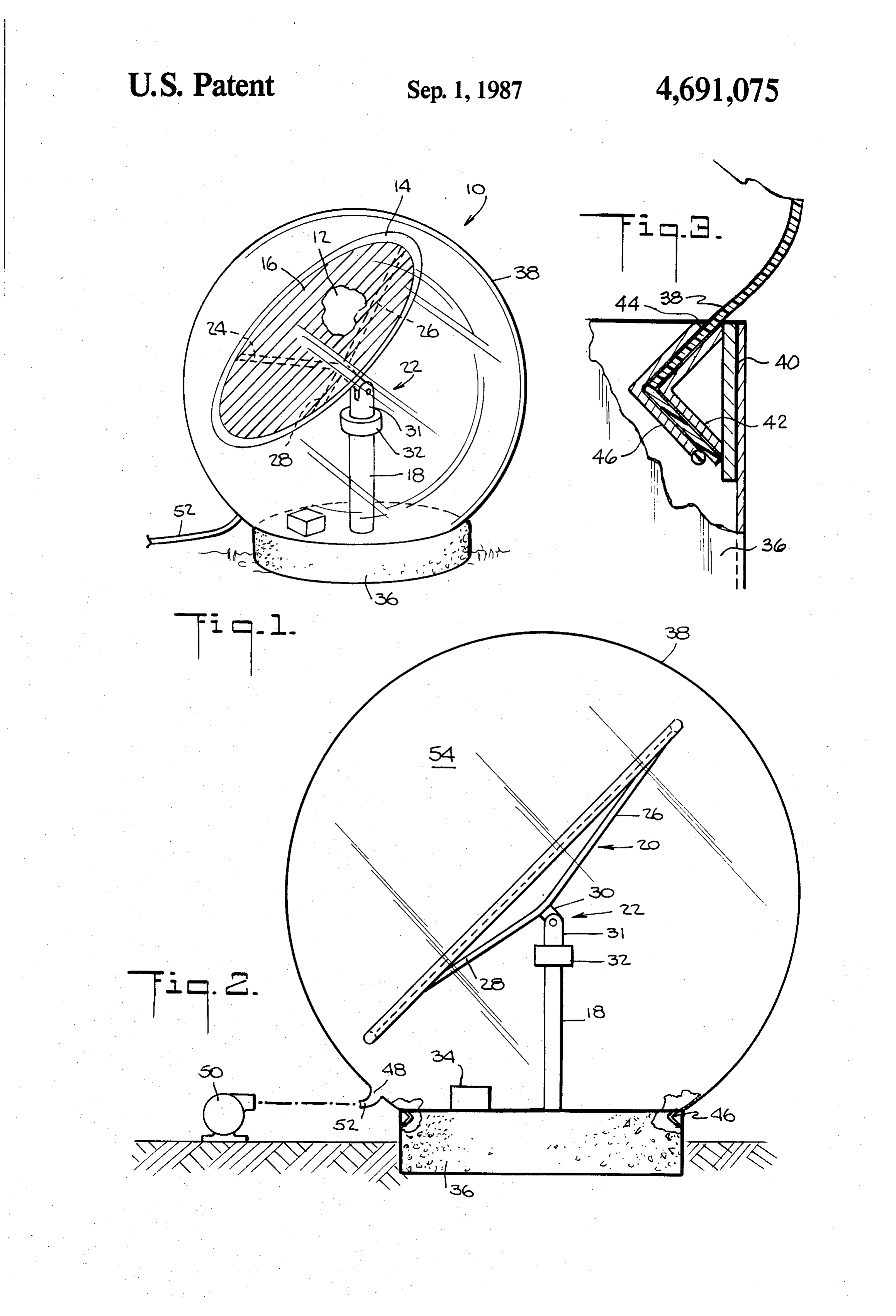
BRIEF DESCRIPTION OF THE DRAWING be formed of steel or any other suitable material. The struts 24, 26, and 28 have one end connected to the rim
The accompanying drawing of an energy conversion 14 with the opposite ends converging toward an eleva system, which is incorporated in and forms a part of the tion pivot joint 30 of the two-axis drive 22. The eleva specification, illustrates a preferred embodiment of the tion pivot joint 30, which tilts the rim 14 at desired present invention and together with the description predetermined angles, includes an ear piece 31 joined to explains the principles of the invention. In the drawing: an azimuthal pivot joint shown schematically at 32. The FIG. 1 is a perspective view of an energy conversion azimuthal pivot joint 32 swivels the ear piece 31 about system incorporating one embodiment of the present an axis that is coincident with the pedestal 18. Thus the invention; 10 azimuthal pivot joint 32 also swivels the rim 14. FIG. 2 is a side elevation thereof; and, The two-axis drive 22 is of the type, but of a less FIG. 3 is an enlarged fragmentary sectional view of a robust construction than those, often used with helio dome securing arrangement. stats such as manufactured by McDonnell Douglas, the Corresponding reference characters indicate corre Arco Solar Company, and Martin Marietta Corpora sponding parts throughout the several views of the 15 tion. A microcomputer for governing the movement of drawing. the two-axis drive 22 is schematically indicated by the DETALED DESCRIPTION OF THE reference number 34 in FIG. 2.
PREFERRED EMBODIMENT The pedestal 18, which is formed of any suitable An energy conversion system incorporating a pre material such as steel or concrete is rigidly affixed to a ferred embodiment of the invention is generally indi base 36, also formed of concrete, or other suitable base material.
cated by the reference number 10 in FIG. 1. An enclosure 38 preferably in the form of a spherical The energy conversion system 10 includes a stretched dome encloses all of the previously described compo membrane 12, a portion of which is shown in FIG. 1, nents supported on the base 36. The dome 38 is a flexi stretched onto a rim 14 to form a platform or mount for 25 ble, inflatable structure, preferably formed of a strong, a PV array 16. The stretched membrane 12 is a thin film formed of a polymeric material, approximately 0.002 to tear resistant or rip stop polymeric material. The wall 0.010 inches (50 to 250 microns) thick, preferably 0.005 thickness of the dome is preferably in the range of 0.002 to 0.006 inches thick (125 to 150 microns).
The membrane 12 can be maintained at a predeter 30 The36enclosure 38 is sealed against the periphery of the mined tension on the rim 14 in any suitable known man base by any suitable clamping arrangment such as ner. For example, the membrane 12 can be bonded or shown in FIG. 3. For example, a collar 40 having a V-shaped projection 42 is affixed to the base 36. A pe otherwise secured to the rim 14 while the rim 14 is held in compression. When the compression on the rim 14 is ripheral end portion 44 of the enclosure 38 is draped released, the membrane 12 becomes tensioned a prede over the V-shaped projection 42 and clamped thereto by a clamping ring 46 of complementary shape to the termined amount.
Attachment of the membrane 12 to the rim 14 can V-shaped projection 42.
also be accomplished by clamping or welding, or in a The enclosure 38 also includes an opening or valve manner similar to that in which screens are attached to 48, as illustrated in FIG. 2, through which air is fed by ... windows or doors wherein the membrane is forced into a fan 50 that communicates with the opening 48 through a crevice (not shown) around the periphery of the rim a tube 52. Preferably the pressure maintained in the 14 with a securing bead insert (not shown). enclosure 38 is approximately 0.02 pound to 0.1 pound A suitable polymeric material for the membrane 12 is per square inch. Although not shown, appropriate pres sold under the trademark Flexigard manufactured by sure control devices, such as a pressure relief valve, can the 3M Company of Minneapolis, Minn. Suitable metal 45 be used to maintain the desired pressure level. lic materials for the membrane 12 are aluminum and The dimensions of the energy conversion system 10 steel. are a matter of choice. Nevertheless, to exemplify mag The PV array 16 can be an array of crystalline PV nitudes that are considered practical, the diameter of cells that are made in the shape of wafers, small disks, or the rim 14 can be approximately 10 meters. The enclo coupons that can be trimmed into rectangular shapes to 50 sure 38 is preferably slightly larger to provide suitable provide adjacent side-by-side contact between the cells. clearance for the pivoting and swiveling rim 14. PV cells of the type manufactured by The Arco Solar In using the energy conversion system 10, the two Company and the Solarex Company are suitable for the axis drive 22 is used to track the solar radiation in accor purposes of this invention. Another kind of PV array is dance with a suitable program furnished in the mi formed of amorphous silicon instead of a crystalline 55 crocomputer 34. The enclosure 38 provides a tranquil structure. The amorphous silicon structure is formed in space 54 that is not interfered with by the weather or sheets that are larger than any of the crystal cells. The deleteriously affected by prevailing winds. Thus an Sanyo Corporation and the Sharp Corporation manu isolated, protected environment is provided in the en facture amorphous silicon PV arrays suitable for the closure space 54.
purposes of this invention. 60 The energy produced by the PV array 16 is used to The PV array 16, whether it be of a cell-type struc power the fan 50 and the two-axis drive 22, thereby ture or an amorphous structure, can be bonded to the rending the system 10 self-powered during times of membrane 12 using a suitable adhesive. insolation. The energy provided by the PV array 16 is The rim 14 is supported on a pedestal 18 by a support DC power, which can be converted to AC power if spider 20 that is joined to a two-axis drive shown in 65 desired. At night and in periods of no insolation, the simplified schematic by the reference number 22. The power required to keep the enclosure 38 inflated can be support spider 20 includes a plurality of struts, prefera supplied by a battery or from power drawn from an bly three struts 24, 26, and 28 spaced 120° apart that can electrical grid, not herein illustrated.
Page 5scan →
Note also that the enclosure 38 can have relatively provide an electric power source, said thin film low specularity requirements since the solar radiation is being stretched and mounted on a circular rim; merely received by the PV array and is not reflected. support means connected to said rim for supporting Thus neither the wall of the enclosure 38 nor the mem said array of photovoltaic cells in a position brane 12 supporting the PV array need have an optical 5 adapted to be exposed to solar radiation, said sup surface of high accuracy, especially since diffuse light at port means being adjustable about two orthogonal the enclosure 38 is received by the PV array 16. Conse axes and having strength design parameters suffi quently the solar radiation need not pass through the cient to support the array, substrate membrane, and enclosure 38 to the PV array in a straight beam. There rim safely in a still atmosphere without regard to fore, the enclosure 38 may be translucent if desired. In 10 ambient outside wind and hail loads; and a practical sense, the membrane films, such as those a substantially spherical dome positioned over and described above for the enclosure 38, can be transparent enclosing a chamber around said array of photo to the extent of being able to see through the film; how voltaic cells and support means, said dome being ever, it does not have to be so specularly transparent comprised of a specularly translucent, flexible, thin that light rays enter and leave the film without scatter film material anchored around said support means ing, i.e., that no diffusion occurs. On the contrary, since and inflated to a pressure in the chamber in the the PV cells can function quite effectively regardless of range of about 0.02 to 0.10 pounds per square inch whether the incident solar radiation is direct or has been more than the pressure outside the chamber, the distorted or scattered, the film membrane 38 can be thin film material of said dome also being tear made of a material that causes some distortion or scat resistant and sufficiently strong to withstand nor tering of solar radiation transmitted therethrough, i.e., mal wind and hail storm forces and having suffi specularly translucent. Consequently, the film mem cient resilience to yield without puncturing to hail brane 38 can be made of materials that are quite strong stones, yet to recover to its spherical surface shape and not subject to being ripped or punctured by hail or 25 under the urging of the inflation pressure in the chamber.
other airborne debris in a storm. Polymeric materials 2. The apparatus of claim 1, wherein said rim is sub such as those available under the trademarks Tefzel made by Dupont and Halar made by Allied Chemical stantially circular and positioned substantially concen tric with said dome enclosure and said substrate is are satisfactory for this purpose.
Some advantages of the invention evident from the 30 stretched in a flat plane over said rim and the photovol foregoing description are an energy conversion system said substratesaidfilmarray taic cells of are mounted in said chamber on such a manner that they are ex 10 that provides a protective shield for PV array 16, posed directly to solar radiation, including scattered which permits the PV array 16 to be mounted on a solar radiation, in the chamber with no intervening lens, stretched membrane 12, which is a low-cost platform, solid light conductors, and light shielding over the pho thereby allowing the use of a low-power draw solar is tovoltaic cells.
tracking arrangement. Since the tension level on the 3. The apparatus of claim 2, including tracking drive enclosure 28 is fairly low, the impact of hail on the means positioned in said chamber and connected me enclosure wall surface will have only minimal effect. chanically to said support means for maintaining said Any surface deflections of the enclosure 38 caused by to array approximately facing the sun and connected elec hail will be corrected by the compliant condition of the 40 trically to said array for powering said tracking drive enclosure material under the influence of the pressur means with electrical energy produced by said array, ized space 54. Furthermore, since the PV array 16 and and including inflating means positioned adjacent said its platform are lightweight and protected from the dome for blowing air into said dome to maintain said wind, a minimally robust and low-cost tracking system pressure therein, said inflating means also being con can be used. The tracking system has a low power draw 45 nected electrically to said array for powering said inflat because of the lightweight structure and because of its ing means with electrical power produced by said ar protection from the wind. In addition, the PV array 16 ray.
requires a very low-accuracy tracking device because it 4. The apparatus of claim 3, including a substantially has the capability of using diffused light. Therefore circular base, said support means being anchored in said since the system is operable with a very low-cost track- 50 base, and said base having an annular collar around its ing device, because of its capability of using diffused periphery, the edges of said thin film material of said light it can function with a low-cost drive system. dome being draped over said collar and clamped to the The foregoing is considered as illustrative only of the base by a substantially circular clamp abutted against principles of the invention. Further, since numerous the collar with the thin film dome material positioned modifications and changes will readily occur to those 55 between the clamp and the collar.
skilled in the art, it is not desired to limit the invention 5. A method of converting solar radiation from the to the exact construction and operation shown and sun to electrical energy, comprising the steps of: described; accordingly all suitable modifications and stretching a thin film membrane substrate over a sub equivalents may be resorted to falling within the scope stantially circular frame and affixing the substrate of the invention as defined by the claims that follow. 60 in stretched condition to said frame to form a flat The embodiments of the invention in which an exclu planar substrate in the scope of a circle; sive property or privilege is claimed are defined as mounting a plurality of photovoltaic cells in an array follows: on one side of said flat planar substrate and electri 1. Light-weight and self-contained solar energy con cally connecting them together to arrange said version apparatus for converting solar radiation to elec- 65 array into an electric power source; trical energy, comprising: mounting said frame on a support structure that is an array of photovoltaic cells mounted on a thin film strong enough to support the frame, substrate substrate membrane and connected together to membrane, and array in a still environment but not 6 designed and built strong enough to support these and fastening and sealing the edges of the enclosure components under wind and hail loads and which membrane around the periphery of the circular base by is capable of adjusting said array about two orthog draping the edges over an annular collar around the onal axes and adjusting the support structure to periphery and clamping the edges between the collar maintain the array oriented approximately perpen and a clamping ring.
dicular to a line extending between the sun and the 7. The method of claim 5, including the steps of con center of the array; necting electrically powered drive means to said sup positioning a large, flexible, thin film enclosure mem port structure, powering said drive means with electric brane that is tear resistant and specularly translu power produced by said array, and controlling the cent concentrically over said array, to enclose said drive means to adjust the orientation of the array auto array, substrate, frame, and support structure as matically to maintain said perpendicular relation be sembly, sealing the edges of the enclosure mem brane, and inflating the enclosure to form an inte tween the array and the sun.
rior chamber over and around said assembly that is 8. The method of claim 7, including the steps of main enclosed by the enclosure membrane, and main 15 taining said pressure in said chamber by positioning an taining the pressure inside the chamber to a suffi electrically powered blower adjacent said enclosure cient amount to support the enclosure film in a with a duct connecting the blower to the interior cham semi-rigid structure over the assembly. ber and powering said blower with electrical power 6. The method of claim 5 including the steps of produced by said array.
mounting the support structure on a rigid circular base s s k k
Provenance
- Collection
- Patents citing this work
- Pages
- 6
- Method
- pdftotext (the PDF's own text layer) + pdftoppm 300dpi page scans
- Patent office record
- patents.google.com →
- Source
- Google Patents citing-documents table
- Assignee
- The United States Of America As Represented By The United States Department Of Energy
- Published
- 1987-09-01
- Transcribed from
- patentimages.storage.googleapis.com →