

patent · US4716491A
High frequency plasma generation apparatus
29 December 1987
Text
Page 1bibliographic recordscan →
United States Patent (19)
Ohno et al.
(54) HIGH FREQUENCY PLASMAGENERATION
APPARATUS
75 Inventors: Yasunori Ohno; Tomoe Kurosawa, both of Hitachi; Tadashi Sato, Mito;
Youichi Ohshita, Hitachi, all of Japan Assignee: Hitachi, Ltd., Tokyo, Japan
30 Foreign Application Priority Data Dec. 11, 1984 JP Japan ................................ 59-2598.84
Int. Cl'............................................... H05H 1/16 52 U.S. C. ............................... 361/230; 204/192.34;
3,467,885 9/1969 Cann ............................... 315/111.71
4,152,625 5/1974 Conrad ........................... 315/111.71
OTHER PUBLICATIONS
Microwave Ion Source by Sakudo et al. publ. Rev. Sci.
A New Production Technique: Ion Milling by Bollin ger et al. publ. by Solid State Technology Nov. 1980. Summary Abstract: Radio Frequency Ion Source De velopment for Neutral Beam Applications by Leung et
Journal of Vacuum Science Tech. Apr.-Jun. 1984. Primary Examiner-L. T. Hix
Assistant Examiner-D. Rutledge
Attorney, Agent, or Firm-Antonelli, Terry & Wands
In a high frequency plasma generation apparatus used in a reactive ion etching apparatus, an ion shower appara tus, a sputter apparatus, etc. for fabricating thin films or semiconductor devices for which a fine patterning pro cess is required, electrical breakdown is apt to be pro voked at the surface of a high frequency coil, because the high frequency coil is usually inserted in a plasma. In order to remove this drawback, according to this invention, the high frequency coil is disposed in the plasma production chamber at the neighborhood of the cylindrical side wall, and thus a plasma confinement domain is formed inside of this high frequency coil by use of a magnetic field production device which gener ates a multi-cusp magnetic field so that the plasma con finement domain is separated from the high frequency coil. In this way, electrical breakdown on the surface of the high frequency coil is prevented and thus the appa ratus according to this invention can work stably for a long time.
6 Claims, 5 Drawing Figures
Drawings
Page 2drawing sheetscan →
Page 3drawing sheetscan →
Page 4drawing sheetscan →
Page 5scan →
duced at its surface by the high frequency electric field
HIGH FREQUENCY PLASMA GENERATION applied to the high frequency coil. This electrical break APPARATUS down can be prevented to a certain extent by an electri
Background of the invention
cal insulation coating on the surface of the high fre 5 quency coil. However, the life of the coating exposed to
This invention relates to a high frequency plasma a reactive gas is short and further the coating on the generation apparatus, and in particular to a high fre surface of the high frequency coil gives rise to a new quency plasma generation apparatus suitable to a reac problem in that the interior of the plasma producing tive ion etching apparatus, an ion shower apparatus, a chamber is polluted by gas released by the coating ma sputter apparatus, etc. for fabricating thin films or semi 10 terial.
conductor devices.
Recently it has been studied to utilize a high fre SUMMARY OF THE INVENTION quency plasma generation apparatus in a reactive ion This invention overcomes the problematical points etching apparatus, an ion shower apparatus, a sputter stated above and its object is to provide a high fre apparatus, etc. for fabricating then films or semiconduc 15 quency plasma generating apparatus to prevent electri tor devices for which a fine patterning process is re cal breakdown on the surface of the high frequency coil quired. without providing an electrical insulation coating and Plasma generation apparatuses known at the present to make the apparatus work stably for a long time. time are ion sources for ion beam working apparatuses, This object can be achieved by the features of the in which arc discharge is maintained by thermal elec 20 present invention, in that a high frequency coil is dis tron emission from a filament and plasma is generated posed in a plasma generation chamber and is formed at with a high frequency by a magnetic field produced by the neighborhood of the cylindrical side wall by sealing a solenoid coil, from which plasma ions are extracted. hermetically the two extremities of the cylindrical side Working apparatuses using this kind of ion sources are wall. The high frequency coil generates high frequency explained e.g. in "A New Production Technique: Ion 25 discharge by introducing gas for porducing ions by Milling” by D. Bollinger and R. Fink, Solid State Tech discharge and at the same time by feeding it with high nology, November 1980.
When this kind of plasma generation apparatus works main is formed by power.
frequency electric A plasma confinement do a magnetic field producing means, with a reactive gas, long time work is difficult for the which reasons that the filament is consumed excessively, that 30 the highgenerates frequency a multi-cusp magnetic field inside of coil.
some gases make the electrodes dirty, etc.
In order to remove these drawbacks, it is sufficient to BRIEF DESCRIPTION OF THE DRAWINGS realize a plasma generation apparatus using no filament.
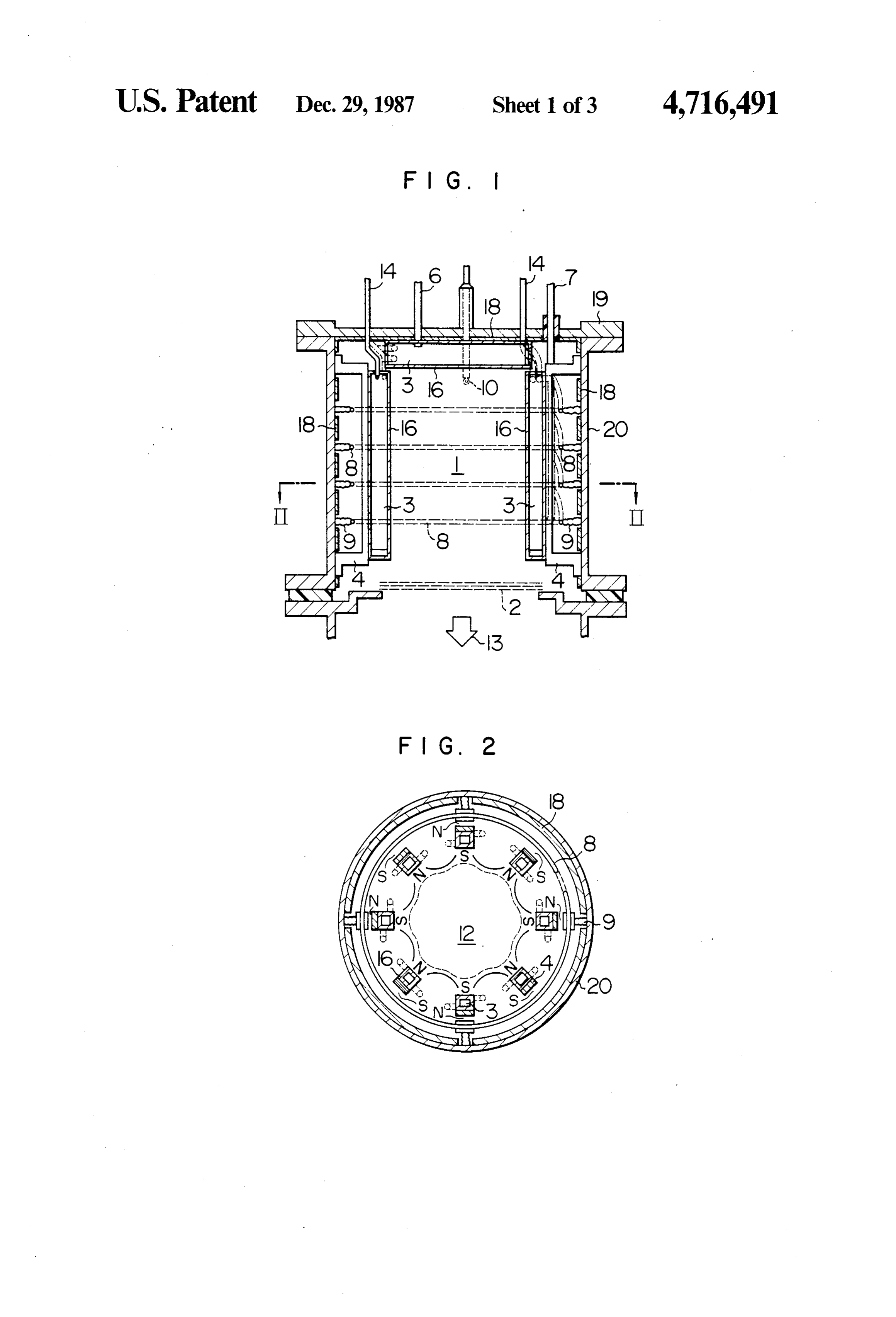
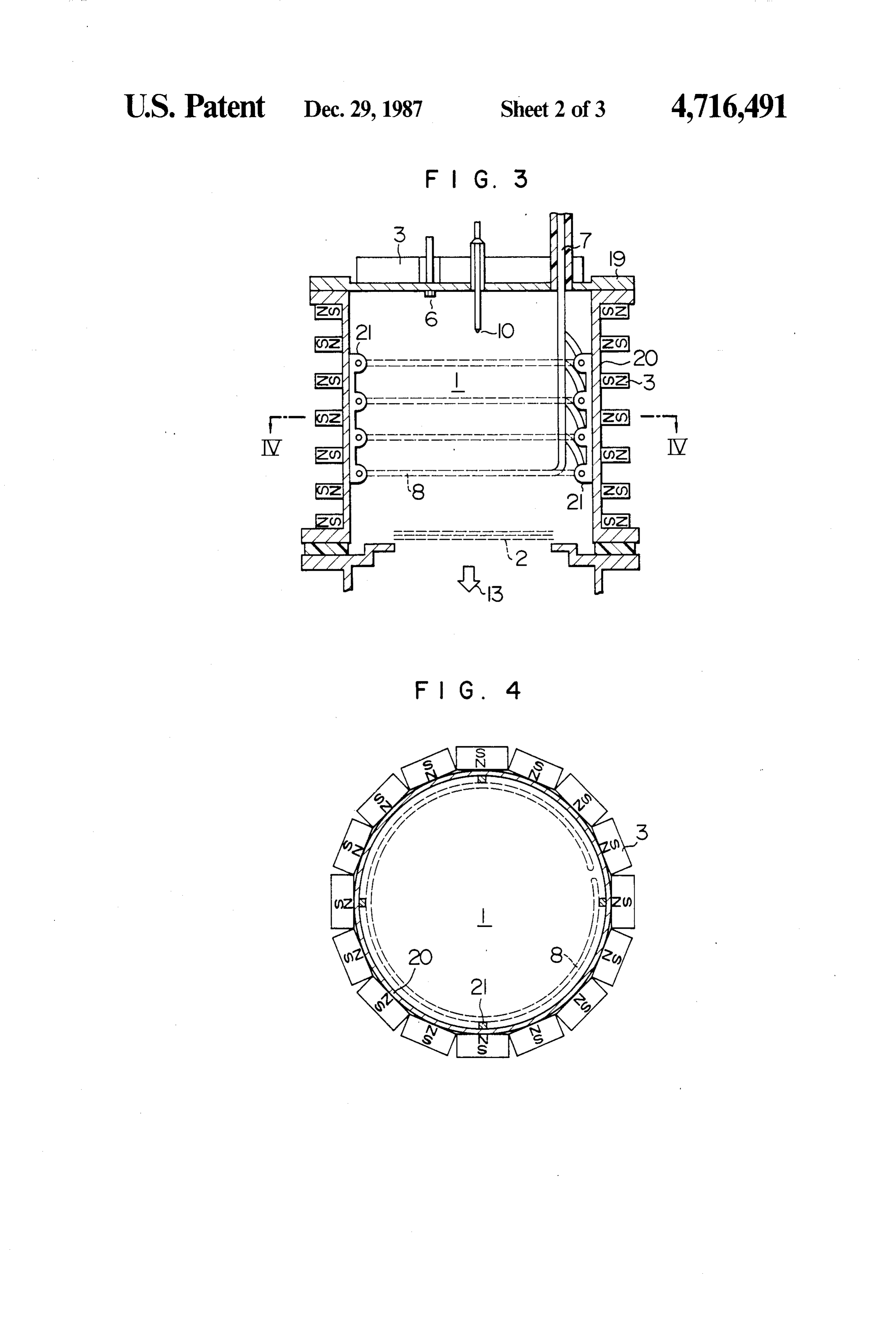
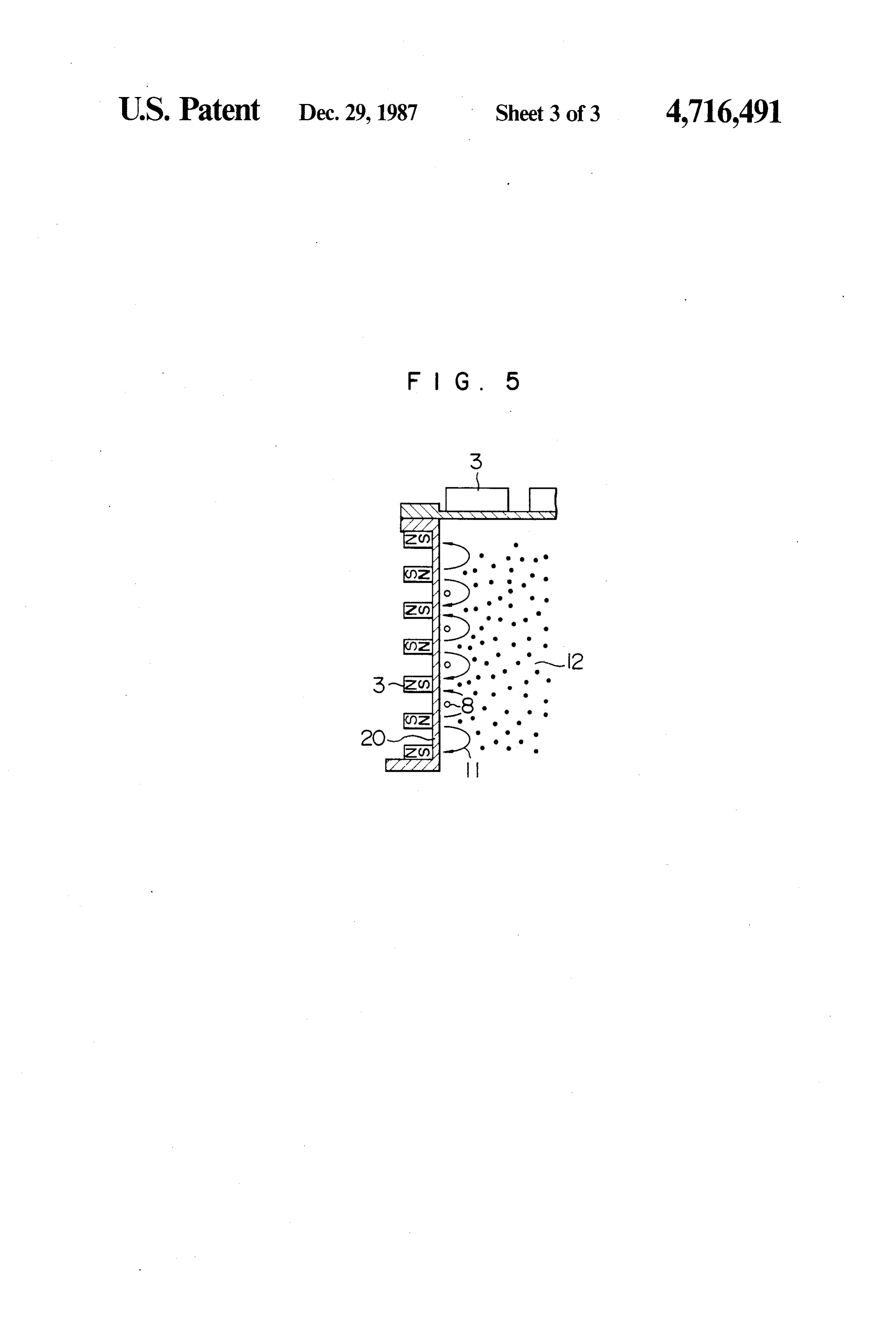
Microwave plasma generation apparatuses are an exam FIG. 1 is a longitudinal cross-sectional view of a high ple of this type of plasma generation apparatus. This 35 frequency plasma generation device according to an kind of apparatus is explained in detail e.g. in "Micro embodiment of this invention;
wave Ion Source' (N. Sakudo, et al., Rev. Sci. Instrum., FIG. 2 is a cross-sectional view along II-II in FIG. Vol. 48, No. 7, July, 1977). In these microwave plasma 1;
generation apparatuses, plasma is produced by micro FIG. 3 is a longitudinal cross-sectional view of a high wave electric power and provides a high quality ion frequency plasma generation device according to an beam suitable in particular for working semiconductor other embodiment of this invention; devices. However, they have drawbacks in that the FIG. 4 is a cross-sectional view along IV-IV in apparatus is too complicated and that it is difficult to FIG. 3; and enlarge the diameter of the beam. FIG. 5 shows schematically the principal part of Further, another example of plasma generation appa 45 FIG. 3 for explaining this invention. ratuses having no filament, are high frequency plasma DESCRIPTION OF THE PREFERRED generation apparatuses which have been reported in EMBODIMENTS "Radio Frequency Ion Source Development for Neu tral Beam Application' (K. H. Leung et al., J. vac. Sci. Hereinbelow some preferred embodiments of this Technol. A2(2), April-June, 1984) as ion sources for 50 invention will be explained, referring to the drawings. neutral particle injection devices, which additionally FIG. 1 is a longitudinal cross-sectional view of a high heat plasma for nuclear fusion. frequency plasma generation apparatus, in which a In such a high frequency plasma generation apparatus plasma production chamber 1 is formed by sealing the a plasma production chamber is formed by sealing the upper end of the cylindrical side wall 20 with a back upper end of the cylindrical side wall with a back plate, 55 plate 19 and at the same time by sealing its lower end and a high frequency coil is disposed at its central por with a vessel not shown in the figure. To the side wall tion inside the chamber. Further, a starter filament and 20 is fixed an extremity of each of insulating supporters a gas inlet are introduced therein through this back 9, on the other extremity of which a high frequency coil plate and a permanent magnet, which generates a multi 8 is mounted. The high frequency coil 8 is located at the cusp magnetic field, is disposed on the peripheral por neighborhood of the side wall 20 and feeded with high tion of the cylindrical side wall. In this way, plasma is frequency electric power through a bushing 7 intro produced by high frequency discharge by means of the duced hermetically and electrically insulated through high frequency coil disposed in the plasma production the back plate 19. Furthermore, magnetic bodies 18 chamber and it is confined in a vessel by the multi-cusp such as soft magnetic ferrite are mounted on the inner magnetic field. 65 surface of the side wall 20 and also the two legs of However, by this construction, since the high fre insulating supporters 4 disposed inside of the high fre quency coil is inserted in a plasma having an electric quency coil 8 are fixed thereto. On the inner surface of conductivity, electrical breakdown is apt to be pro these supporters 4 and of the back plate 19 are mounted 6 permanent magnets and a magnetic field generation indicated above, the apparatus described in this embodi means 3 in order to produce a multi-cusp magnetic field. ment can work stably for a long time, even if reactive The soft magnetic ferrite 18 stated above forms a mag gas is used in order to extract a large amount of ion netic return path for the high frequency magnetic field beam, while preventing electrical breakdown on the produced by the high frequency coils 8. Further the surface of the high frequency coil 8. Further, since the high frequency coil 8 consists of a round tube cooled by plasma is confined in a determined plasma confinement water or oil flowing therethrough. domain 12 by the multi-cusp magnetic field, an almost The magnetic field production means 3 mentioned uniform plasma can be obtained in spite of a large above is disposed in 8 rows in the plasma production plasma confinement domain 12 and it is easy to enlarge chamber 1, as indicated in FIG. 2, which generates a 10 the diameter of the beam. That is, enlargement of the multi-cusp magnetic field and forms a plasma confine diameter of the beam can be realized by increasing the ment domain 12 indicated by a broken line in the figure. number of the magnetic field production means 3 or This plasma confinement domain 12 is located inside of making it stronger so as to obtain an intensity of the the high frequency coil 8, which is protected against the magnetic field, which is sufficient to confine the plasma. plasma. Further the magnetic field production means 3 15 FIG. 3 illustrates another embodiment of the high is located in a water or oil cooled case 16, which permits frequency plasma production apparatus of this inven to avoid overheating due to plasma loss. The supply of tion.
this cooling medium is effected through a cooling me In this embodiment, the magnetic field production dium introducing inlet 14 passing hermetically through means 3 for generating a multi-cusp magnetic field is the back plate 19. Furthermore a gas inlet tube 6 and a 20 disposed outside of the vessel forming the plasma pro starter filament 10 pass hermetically through the back duction chamber 1. Further the magnetic field produc plate 19. Reactive gas such as O2 is introduced through tion means 3 have N poles and Spoles disposed alter this gas inlet tube 6 and thermal electrons are emitted by nately along the axial direction on the side wall 20 and heating the starter filament 10. at the same time the poles of same polarity are arranged The working mode of the apparatus illustrated in 25 almost conintuously in the circumferential direction on FIGS. and 2 will be explained below. the side wall, as indicated in FIG. 4. In the case indi After having evacuated the plasma production cham cated in the figure, the magnetic field production means ber 1 to a vacuum of about 6.7 x 10⁻⁴ Pa (5X 10⁻⁶ 3 are arranged in a ring shape consisting of 7 layers with Torr), reactive gas is introduced therein through the gas a predetermined interval in the axial direction on the inlet tube 6 so that the pressure in the chamber 1 is about 30 side wall 20, and the high frequency coil 8 is so disposed 1.3X 10⁻¹-1.3 Pa (1-10 m Torr). Then, thermal elec that each turn is located between two adjacent layers at trons are emitted by the starter filament 10 by heating it the neighborhood of the side wall 20 of the plasma and at the same time, plasma of the reactive gas is pro production chamber 1 and fixed to the side wall 20 by duced in the plasma production chamber 1 by feeding an insulating supporter 21. The other constructions are the high frequency coil 8 with high frequency electric 35 identical to those described for the preceding embodi power of 13.56 MHz. After the plasma has been stabi ment. The identical or equivalent items are designated lized, power supply to the filament 10 is stopped. Elon by same reference numerals and explanation more in gation of the life of the starter filament 10 can be ex detail therefor will be omitted.
pected either by making it recoil from the plasma do FIG. 5 shows schematically the situation of the main after the stop of the power supply or by replacing plasma confinement in the high frequency plasma pro it by a discharge gap. The produced plasma has a ten duction apparatus having the construction according to dency to diffuse towards the wall surface of the plasma this embodiment. The magnetic field production means production chamber 1, but it is confined within the 3 disposed on the outer surface of the side wall 20 gen domain i2 indicated in FIG. 2 by a multi-cusp magnetic erates a magnetic field in the direction indicated by an field generated by a magnetic field production means 3. 45 arrow 11. Consequently, although the plasma generated An ion beam 13 can be extracted from the plasma by by high frequency discharge has a tendency to diffuse applying a predetermined voltage to an electrodes 2 towards the side wall 20, the diffusion is prevented by disposed in the bottom portion of the plasma production the magnetic field mentioned above and ions are con chamber 1. fined in the domain 12 indicated by black points in the As it is clear from the working mode explained 50 figure. In this way, electrical breakdown due to the above, in this embodiment, since the high frequency coil plasma produced by the high frequency coil 8 can be 8 is disposed outside of the plasma confinement domain prevented. Therefore, the same effects as those obtained 12 by means of the magnetic field production means 3, in the preceding embodiment can be obtained also in that is, since the high frequency coil is separated from this embodiment.
the plasma confinement domain by the magnetic field, 55 Further, the magnetic field production means 3 may electrical breakdown on the surface of the high fre be either an electromagnet or an permanent magnet, as quency coil due to the plasma is prevented without stated previously, or still further their combination. In providing electrical insulation coating thereon. Conse the case where a permanent magnet is used, it is desir quently, the apparatus can work stably for a long time. able to use a magnet fabricated by moulding magnetic By using the apparatus described in this embodiment, 60 powder with resin, because heat production by the high plasma of O2 gas was produced and an ion density of frequency magnetic field is reduced in this way. Fur 0.8-1.0X 101 (cm) in the plasma was obtained. Fur thermore, the apparatus can be used as an etching appa ther a beam of O2 ions of 500 eV was extracted from the ratus or a sputtering apparatus, when the ion beam plasma and an ion beam current density of 0.65 extraction electrode 2 is removed from the construction mA/cm2 was obtained. In addition, the maintenance 65 indicated in the embodiments stated above and material interval, i.e. the period of time during which the appara to be worked is brought directly into contact with the tus can be used without maintenance, is 5 times as long plasma or reactive radicals, and thus it can be widely as that for a prior art apparatus using a filament. As utilized as a high frequency plasma generation appartus.
Page 7scan →
In addition, although examples, where only reactive gas magnetic field generation means for generating a is used, are described in the above embodiments, non multi-cusp magnetic field for producing a plasma reactive gas can be also used. confinement domain inside of said high frequency By the high frequency plasma generation apparatus coil, wherein said plasma is confined within said according to this invention, as explained above, since plasma confinement domain so as to prevent the plasma production chamber is formed by sealing contact between said plasma and said high fre hermetically the two extremities of its cylindrical side quency coil.
wall; a high frequency coil is disposed in the high fre 2. A high frequency plasma generation apparatus quency plasma generation chamber, which generates according to claim 1, in which said high frequency coil high frequency discharge by introducing gas for pro O is mounted at an end of each of insulating supporters, ducing ions by discharge and at the same time by feed the other end of said insulating supporters being fixed to ing it with high frequency electric power; and a mag said cylindrical wall means.
netic field generation means producing a multi-cusp 3. A high frequency plasma generation apparatus magnetic field for confining a plasma in the plasma according to claim 1, in which said magnetic field gen production chamber is disposed at the neighborhood of 15 eration means is disposed in said plasma production the cylindrical side wall, the plasma is separated from chamber inside of said high frequency coil and con the high frequency coil such that electrical breakdown structed so as to have poles whose polarity varies alter on the surface of the high frequency coil due to the nately in the circumferential direction of said wall plasma is prevented and thus it is possible to obtain a 63S.
high frequency plasma generation apparatus, which can 20 4. A high frequency plasma generation apparatus work stably for a long time. according to claim 3, in which said magnetic field gen We claim: eration means is provided with magnetic bodies forming 1. A high frequency plasma generation apparatus magnetic return paths for said multi-cusp magnetic field comprising: inside of said cylindrical wall means. cylindrical wall means; 25 5. A high frequency plasma generation apparatus means for hermetically sealing two ends of said cylin according to claim 3, in which said magnetic field gen drical wall means, so as to form a high frequency eration means is disposed in a cooled case. plasma production chamber within said cylindrical 6. A high frequency plasma generation apparatus wall means; according to claim 1, in which said magnetic field gen means for introducing a gas into said high frequency 30 eration means is disposed on the outer surface of said plasma production chamber; cylindrical wall mean and constructed so as to have a high frequency coil, disposed in said high frequency poles whose polarity varies alternately in the axial di plasma production chamber in the neighborhood of rection of said wall means and is unchanged almost said cylindrical wall means, for providing high continuously in the circumferential direction of said frequency electric power to said gas so as to pro 35 side wall.
duce a plasma; and k k t
Provenance
- Collection
- Patents citing this work
- Pages
- 7
- Method
- pdftotext (the PDF's own text layer) + pdftoppm 300dpi page scans
- Patent office record
- patents.google.com →
- Source
- Google Patents citing-documents table
- Assignee
- Hitachi, Ltd.
- Published
- 1987-12-29
- Transcribed from
- patentimages.storage.googleapis.com →