

patent · US4745896A
Upper cylinder area lubrication system
24 May 1988
Text
Page 1bibliographic recordscan →
United States Patent (19)
Schultz
(54) UPPERCYLINDER AREALUBRICATION
SYSTEM
Inventor: Robert A. Schultz, 907 Town &
Country Blvd., Suite 202, Houston,
51 Int. Cl." ............................................... F01M 1/00 52 U.S. Cl. ............................. 123/196M; 123/90.33
2,721,545 10/1955 Harvey ........................... 123/196M 2,722,210 1 1/1955 Koonce .......................... 123/156 M 2,745,396 5/1956 Harvey ........................... 123/196 M
3,095,866 7/1963 Dionne ........................... 123/196 M 3,115,874 12/1963 Roberts .......................... 123/196 M
3,827,417 8/1974 Morita ......... - - - - - - - 123/196 M.
Primary Examiner-E. Rollins Cross
Attorney, Agent, or Firm-Vaden, Eickenroht
Thompson & Boulware
An upper cylinder area lubrication system is disclosed that dispenses a small amount of lubricant to the upper cylinder area of an internal combustion engine at regu lar intervals for a metered period of time. Typically, the lubricant is dispensed for one second every thirty min utes. An electric pump is used to draw the lubricant from the reservoir and apply it, preferably through a mixing chamber in the gasoline line located just before the gasoline is applied to the firing chambers. The con trol of the pump is via a solid-state timing device that separately sets the alternate on periods and the off peri ods.
11 Claims, 1 Drawing Sheet
Drawings
Page 2drawing sheetscan →
Page 3scan →
Upper cylinder area lubrication summary of the invention
SYSTEM The upper cylinder area lubrication system for an internal combustion engine in accordance with the pres
BACKGROUND OF THE INVENTION 5 ent invention generally includes a conduit means, such 1. Field of the Invention as for example a mixing chamber where the gasoline or other fuel is mixed with lubricant, a lubricant supply
This invention pertains to automatically lubricating means the upper cylinder area of an internal combustion en lubricant and timer means for automatically dispensing the gine. in a predetermined manner. The lubricant 10 supply means includes a reservoir for the lubricant and 2. Description of the Prior Art an electric pump that dispenses lubricant for typically a Internal combustion engines generally are inade second or so when it is controlled on. More specifically, quately lubricated in their upper cylinder areas. As a the electric pump is controlled on/off by timer means result, it is well-known that the cylinders and other preferably comprising two timers, one for determining parts of an internal combustion engine have a much 15 the duration of off periods (typically, of 30 minutes shorter life span than the parts of a diesel engine. In duration) and one for determining the duration of the on addition, the parts operate less efficiently than they periods that occur between the off periods (again, typi would if properly lubricated. With the advent of non cally one second periods). This intermittent dispensing leaded gasolines, and especially high octane non-leaded scheme is sufficient to adequately lubricate the area gasolines, that are dryer burning than leaded gasolines, without rapidly depleting the reservoir or creating this problem of inadequate lubrication is exacerbated. gumming or other undersirable engine conditions when Internal combustion engines that operate with methane too much lubricant is applied. The parts are long-acting fuel are even more notoriously poorly lubricated in and do not interfere with the normal operation of the their upper cylinder areas than are gasoline internal parts by imparting a constant pressure condition. combustion engines because of the extremely dry burn 25 BRIEF DESCRIPTION OF THE DRAWINGS ing conditions. The problem exists with internal com bustion engines with fuel injectors as well as those with So that the manner in which the above-recited fea Out. tures, advantages and objects of the invention, as well as Attempts in the prior art to provide upper cylinder others which will become apparent, are attained and area lubrication include the system described in U.S. 30 can be understood in detail, more particular description Pat. No. 3, 15,874, which basically puts lubricant into of the invention briefly summarized above may be had the upper cylinder by drawing a vacuum on a lubricant by reference to the embodiments thereof which are reservoir and applying the lubricant through a valve in illustrated in the appended drawings, which drawings a manifold. Metering is provided through a "bi-metal' form a part of this specification. It is to be noted, how valve that determines the opening depending on the 35 ever, ferred that the appended drawings illustrate only pre embodiments of the invention and are therefore heat of the engine. The amount of lubricant applied is often entirely too much, however, since lubricant is not to be considered limiting of its scope as the inven constantly applied. As a result, the lubricant reservoir tionIn may admit to other equally effective embodiments. the drawings:
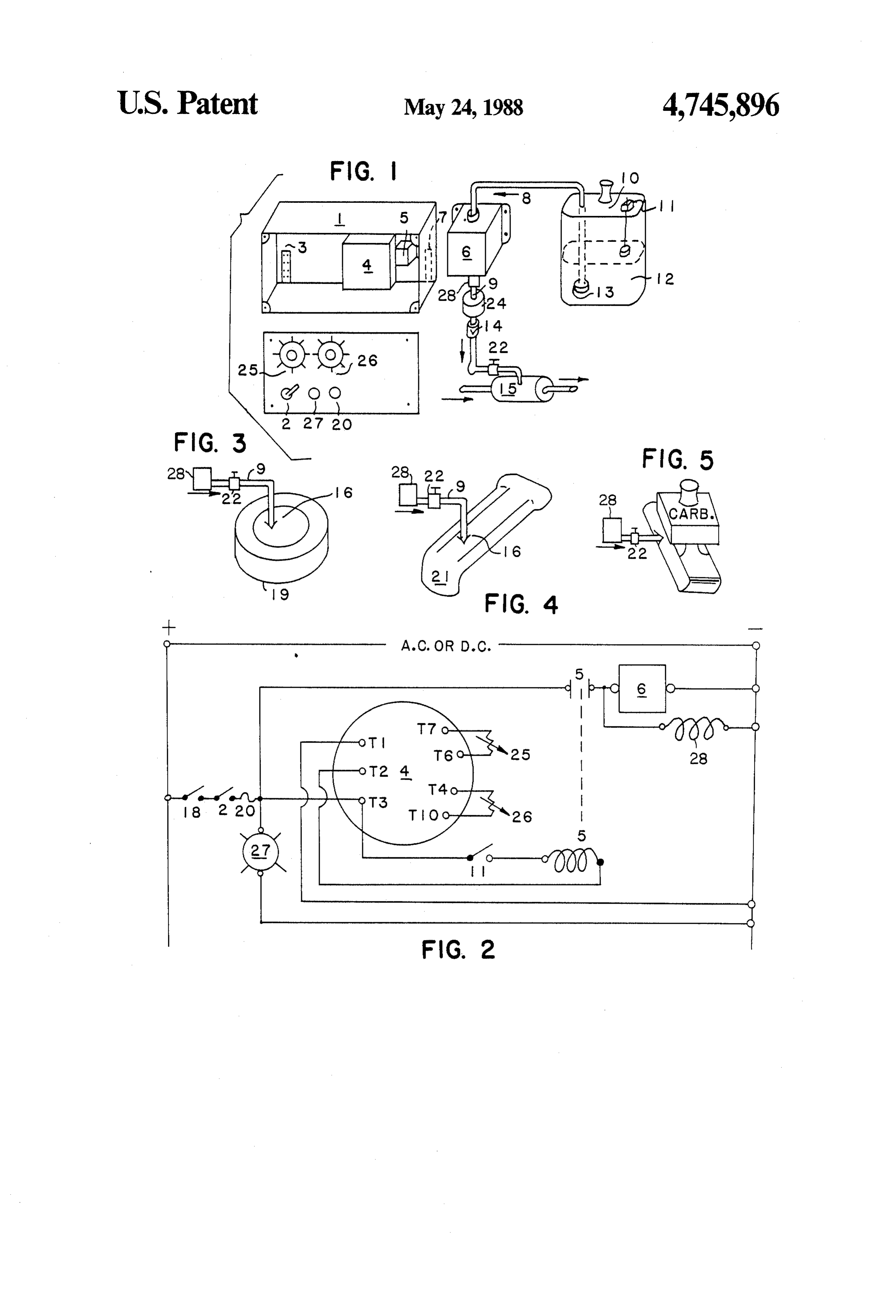
empties faster than is economical or practical and there FIG. 1 is a mechanical schematic representation of an is a gumming effect on the operating parts that are upper cylinder area lubrication system in accordance
U.S Pat. No. 2,721,545 describes another system for with a preferred embodiment of the present invention. lubricating the upper cylinder area of an internal com trical FIG. 2 is an electrical schematic diagram of the elec bustion engine, this system using a fine spray or mist 45 FIG.portion of the system shown in FIG. 1. head to dispense the lubricant more uniformly over the portion 3ofisthe a mechanical schematic representation of a upper cylinder area lubrication system in parts than with a delivery scheme not including such a accordance with an alternate preferred embodiment of head. The lubricant is constantly applied, however, as the present invention.
with the '874 system. There is no known spray head that FIG. 4 is a mechanical schematic representation of a dispenses with a fine enough spray to be both efficient 50 portion of an upper cylinder area lubrication system in and non-wasteful. That is, the '545 scheme also dis accordance with another alternate preferred embodi penses much too much lubricant to be commercially ment of the present invention. acceptable. FIG. 5 is a mechanical schematic representation of a Therefore, it is a feature of the present invention to portion of an upper cylinder provide an improved system for lubricating the upper 55 accordance with yet anotherarea lubrication system in alternate preferred em cylinder area of an internal combustion engine that bodiment of the present invention.
dispenses only the required amount of lubricant at inter mittent intervals. DESCRIPTION OF PREFERRED It is another feature of the present invention to pro EMBO)IMENTS vide an improved system for lubricating the upper cyl 60 Now referring to the drawings and first FIG. 1, a inder area of an internal combustion engine that utilizes preferred embodiment of a fully automatic, electronic long-acting solid state timer means. lubrication system in accordance with the present in It is still another feature of the present invention to vention is shown in mechanical schematic representa provide an improved system for lubricating the upper tion. The system is designed to lubricate the upper cyl cylinder area of an internal combustion engine that 65 inders, rings, piston chamber walls and valves of a gaso utilizes a long-acting electric pump that does not impart line or similarly fueled internal combustion engine a constant pressure condition on the operating engine every time the engine is turned on. Referring to the parts, as with the '874 system. components illustrated in FIG. 1, an enclosure 1 is lo 4 cated underneath the hood or under the dashboard area turned on to activate the engine, the system is enabled of the cockpit of the vehicle serviced by the internal and the timers are started. For the duration of each off combustion engine to be lubricated and includes posi period, no lubrication is supplied to the engine. How tive terminal strip 3 and negative terminal strip 7 for ever, when the "off" period expires, the "on" period making electrical connections to the power system of 5 timer energizes the coil of relay 5, thereby closing its the vehicle. Included in the enclosure is timing control contacts and causing electric pump 6 to operate for a 4 described more fully hereafter, that activates an elec short period of time, typically one second. During the tric relay 5. An isolation switch 2 is included for dis "on" period, electric pump 6 draws a measured quantity abling the entire system, if desired, and is located of lubricant from the reservoir and pressure pumps the mounted to cover 17 of the enclosure. Hence, switch 2 10 lubricant into mixing chamber 15, located in the gaso provides a convenient electrical disconnect for the unit line line as described above. The lubricant is mixed with from the electrical system of the vehicle. the gasoline in chamber 15 precisely in a proportion Also included underneath the hood of the vehicle is ately measured amount. Thereafter, the mixture is in lubricant reservoir 10 filled with an appropriate lubri jected into the firing chambers of the engine. The dis cant 12 for dispensing via tubing 8 to electric lubricant 15 pensing head which is connected to the output tubing pump 6. A filter 13 maybe included at the intake to from the mixing chamber can conveniently include tubing 8, if desired. Also, if desired, a float switch 11 atomizer spray nozzles located in tapped holes in the may be included for ensuring that the electric pump is intake air manifold. If desired, as shown in FIG. 3, the deactivated when the lubricant level falls below a pre output from valve 22 can be applied directly into the determined level. Float switches are commonly em engine air filter at the carburetor of the engine. In this ployed in the art and their manner of operation is well case, a mixing chamber is not used. Alternatively as known. shown in FIG. 4, the lubricant can be pumped directly Lubricant pump 6 is connected by way of tubing 9 to from valve 22 into conveniently located atomizer spray flow control valve 22. If desired, a pressure regulator 24 nozzles located in holes in the engine air intake manifold may be included in the tubing line between lubricant 25 without going through a mixing chamber first. This is pump 6 and flow control valve 22. Also, a one way flow particularly applicable to engines with turbo or fuel valve 14 may be included in this line to prevent any injectors. Finally, as shown in FIG. 5, spray nozzles can possible backup of flow to pump 6. Also, a normally be located directly in the engine intake manifold. closed electric flow valve 28 must be included to pre Now referring to FIG. 2, the wiring diagram for the vent vacuum pull when the system is off provided that 30 vehicle upper cylinder area lubrication system is shown. pump 6 is the kind that does not shut off when not in The electrical power for the system may be either AC use. In such case, valve 28 would not be required. Pref. or DC. It will be seen that timing control device 4 is erably, the solenoid coil of valve 28 is located in parallel connected at terminal T3 through fuse 20, switch 2 and across pump 6, as shown in FIG. 2 and physically the ignition switch 18 to one side of the power system. The valve itself would be located just beneath pump 6, as 35 opposite side is wired directly to terminal T1. Terminal shown in FIG. 1 or ahead of valve 22 in FIGS. 3, 4 and T2 is wired to the coil of relay 5 through float switch 5. 11, which is connected back to terminal T3. The poten In FIG. 1, flow control valve, which may be a simple tiometers or variable resistors for the timers, are also pitcock valve, allows the application of lubricant from shown in the FIG. 2 diagram. The potentiometer for pump 6 to enter a lubricant mixing chamber 15. Cham timer 25 is shown connected to terminalsT6 and T7 and ber 15 also receives the gasoline supply to the engine to the potentiometer for timer 26 is connected to terminals be lubricated. Although theoretically the mixing cham T4 and T10. The contacts for relay 5 are shown in series ber may be located anywhere in the gasoline supply with electric pump 6. Electric pump 6 is connected line, it is most conveniently and efficiently located near directly to one side of the power wiring and through the the engine to be serviced. 45 switch contacts to the opposite side at the junction with The system is operated or controlled by two timers, fuse 20. A pilot light 27 is connected between the same which are most conveniently mounted on cover 17 of points, as shown on the diagram.
the enclosure. Timer 25 includes a potentiometer that A preferred timing device that includes both an "on" may be set so that each time the timer operates, the coil time delay and an "off" time delay is the TRS Repeat of electric relay 5 is energized. The setting for this po 50 Cycle Timing Control marketed by Infitec Inc. of Syra tentiometer allows relay energizing periods from ap cuse, N.Y. This device is a fully solid state digital proximately one half () second to 30 seconds. Timer 26 C/MO timing device and has a specification life of one includes a potentiometer for establishing the off periods hundred million operations minimum under full load. that occur between the on periods set by timer 25. The Although this timing means has proven effective, equiv potentiometer of this timer allows the setting of the off 55 alent means are available. The electric pump employed periods over a range from about 15 minutes to one hour. as pump 6 can be TRW type no. 55469 or other fast Normally timer 25 is set to provide for one second "on' response fuel pump.
operation and timer 26 is set to provide 30 minute "off" The upper cylinder area lubrication system described operation, or less time if desired. In case the vehicle above results in reduction of friction, heat and engine operates primarily in town, or in short time operation, 60 wear and thus increases engine operating life substan the control box can be located near the driver so the off tially. The operation is fully automatic. The only opera timer can be set to a shorter time (15 minutes is sug tor requirement is to maintain lubricant in the reservoir. gested for town driving) and then set back to 30 minutes The reservoir does not empty dramatically when the for highway driving. vehicle is in operation however, since it is not continu Also included and mounted in enclosure cover 17 are 65 ously being drained, as with reservoirs in some prior art a fuse 20, a pilot light 27 to show the circuit is protected Systems.
operational, and deactivating switch 2, previously de The ability to adjust the time periods on and off ena scribed. In operation, each time the ignition switch is bles a precise measured amount of lubricant to be 5 pumped to the engine upper cylinder area to optimize engine includes an air intake manifold, and wherein said the performance of the engine without fouling the spark conduit means terminates in a spray head for introduc plugs or adversely affecting engine operation in any ing the lubricant to said air intake manifold. Way. 5. An upper cylinder area lubrication system in accor While particular embodiments have been shown and dance with claim 1, wherein the internal combustion described, it will be understood that the invention is not engine includes a carburetor and wherein said conduit limited thereto. Many modifications may be made and means terminates in said carburetor.
will be become apparent to those skilled in the art. 6. An upper cylinder area lubrication system in accor What is claimed is:
1. An upper cylinder area lubrication system for an 10 betweenwith dance claim 1, and including a pressure regulator said pump and said conduit means.
internal combustion engine, comprising 7. An upper cylinder area lubrication system in accor conduit means connected to the upper cylinder area dance with claim 1, and including a sensor for monitor of an internal combustion engine for introducing ing the level of lubricant in said reservoir and turning lubricant thereto, off the lubrication system when the lubricant falls below lubricant supply means including 15 a reservoir for containing a lubricant suitable for a predetermined level.
8. An upper cylinder area lubrication system in accor introduction to the upper cylinder area of said dance with claim 1, wherein said timer means operates internal combustion engine, and said pump on for relatively short periods of time in the an electric pump connected to said reservoir and range between 0.5 seconds and 30 seconds and operates timer means for automatically and alternately operat said pump off for relatively long periods of time in the ing said pump on for relatively short periods of range of about 30 minutes.
time and off for relatively long periods of time 9. An upper cylinder area lubrication system in accor while the internal combustion engine is running. dance with claim 8, wherein said timer means includes a 2. An upper cylinder area lubrication system in accor 25 first timer for timing the relatively short periods and a dance with claim 1, wherein said conduit means in second timer for timing the relatively long periods. cludes a mixer for receiving lubricant from said pump 10. An upper cylinder area lubrication system in ac and gasoline from a gasoline feed line, the output from cordance with claim 9, wherein said first timer and said mixer thereby being gasoline mixed with lubricant second timer are solid state devices. during said relatively short periods of time. 30 11. An upper cylinder area lubrication system in ac 3. An upper cylinder area lubrication system in accor cordance with claim 9, wherein said timer means in dance with claim 1, wherein the internal combustion cludes an ignition switch for applying starting power to engine includes an air filter, and wherein said conduit the internal combustion engine when turned on and means terminates in a spray head for introducing the disconnecting power from the internal combustion en lubricant to said air filter and directly above the carbu 35 gine when turned off, said ignition switch connected to retor air intake ports. initiate said timer means when turned on and to discon 4. An upper cylinder area lubrication system in accor nect said timer means when turned off. dance with claim 1, wherein the internal combustion xk ck k sk k
Provenance
- Collection
- Patents citing this work
- Pages
- 5
- Method
- pdftotext (the PDF's own text layer) + pdftoppm 300dpi page scans
- Patent office record
- patents.google.com →
- Source
- Google Patents citing-documents table
- Assignee
- Schultz Robert A
- Published
- 1988-05-24
- Transcribed from
- patentimages.storage.googleapis.com →