

patent · US9816190B2
Energy extraction system and methods
Robert Louis Koeneman · Traver Hall Kennedy for Joi Scientific Inc · 14 November 2017
Text
Page 1bibliographic recordscan →
(12) United States Patent
Koeneman et al.
(54 ) METHODS
ENERGY EXTRACTION SYSTEM AND
( 71 ) Applicants :Robert Louis Koeneman , Cape
Canaveral, FL (US ); Traver Hall
Kennedy, Cape Canaveral, FL (US) ( 72 ) Inventors : Robert Louis Koeneman , Cape
Canaveral, FL (US) ; Traver Hall
Kennedy, Cape Canaveral, FL (US )
(73) Assignee : Joi Scientific , Inc., Merritt Island , FL
( * ) Notice: Subject to any disclaimer, the term of this patent is extended or adjusted under 35
Related U . S . Application Data
(60 ) Provisional application No. 62 /091,702, filed on Dec .
(Continued )
(Continued ) (58 ) Field of Classification Search
See application file for complete search history.
DBliocdkiensg
THAT INA MI CORA UMHUMINA MITIK US009816190B2
(10) Patent No.: US 9 ,816 , 190 B2 (45 ) Date of Patent: Nov. 14 , 2017
U .S . PATENT DOCUMENTS
(Continued )
FOREIGN PATENT DOCUMENTS
CN 202011906 U 10 / 2011 CN 104073838 A 10 /2014 (Continued )
OTHER PUBLICATIONS
International Search Report ( ISR ) PCT/US2015 /065854 — Mar. 10 , 2016 — 6 pages (including notification of transmittal of the ISR and WO of the ISA ).
(Continued )
Primary Examiner — Nicholas A Smith (74) Attorney, Agent, or Firm — Krishna Kalidindi
A system for extracting hydrogen from seawater includes a hollow chamber defined by a cylindrical wall, a cylindrical member within the chamber, a mechanism for recirculating conductive fluid through the chamber, a power supply connected via reactive circuits to the chamber wall to form an anode and to the cylindrical member to form a cathode and providing an input pulse DC voltage during a duty cycle on portion and an off cycle chamber return load circuit connected to the reactive circuits , and an off cycle chamber return load circuit connected to the positive and negative reactive circuits wherein the reactive circuits and the off cycle chamber return load circuit : process voltages returning from the chamber during an off portion of the duty cycle , the returning voltages resulting from an electro -chemical reac tion in the chamber without surface reaction on the cylin drical member, and return the processed voltage to the chamber, wherein the chamber releases hydrogen gas.
19 Claims, 6 Drawing Sheets
Positive Reactive
70uF www
LoadRCOfheyatcmublren
Negative retum to chamber
Negative Reactive
Circuit / Balance
Page 2scan →
U .s . patent documents
2007/ 0272546 A1 * 11/ 2007 Matthews C25B 15 /02
2014 /0367272 A1 * 12 / 2014 Haywood ... ... ... ... ... C25B 15 /08
Foreign patent documents
Other publications
Written Opinion (WO ) of International Search Authority (ISA )
International Search Report (ISR ) — PCT/US2015 /065785 — Mar. 4 , 2016 — 6 pages (including notification of transmittal of the ISR and WO of the ISA ).
Written Opinion (WO ) of International Search Authority (ISA )
http ://web .archive .org/web /20130130100756 /https:// en .wikipedia .
“ Water Eletrolysis with Voltage Inductive Pulses” , Vanags, Martins et al., Electrolysis , Chapter 2 , 2012 .
“ Pulsed DC And Anode Depolarization In Water Electrolysis For Hydrogen Generation ” , Shaaban , Aly H ., Aug . 1994 . “ Economical Hydrogen Production By Electrolysis Using Nano Pulsed DC ” , Dharmaraj, C . H . and Adish Kumar, S .; International Journal Of Energy And Environment, vol. 3, Issue 1, pp . 129 - 136 ,
“ Review Of Pulsed Power For Efficient Hydrogen Production ” , Monk , N . and Watson , S . J.; International Journal Of Hydrogen
“ Effects Of Geometry Of Electrodes And Pulsating DC Input On Water Splitting For Production Of Hydrogen ” , Mandal, Biswajit, Sirkar, A ., Shau , Abhra, De, P . and Ray, P.; International Journal Of Renewable Energy Research , vol. 2 , No. 1, 2012 .
“ Influence Of Electrical Conductivity And pH On Hydrogen Pro duction Using Pulsed Discharge Over The Water Surface” , Ihara , Takeshi, Ide , Yusuke, Nagata , Hideo , Yagyu , Yoshihito , Ohshima,
Tamiko , Kawasaki, Hiroharu , Suda , Yoshiaki; Plasma Science (ICOPS ), 2016 — Abstract.
“ DC Electrical Breakdown Of Water In A Sub -Micron Planar Gap ” , Song , Chunrong and Wang , Pingshan ; IEEE 2009 .
* cited by examiner
Page 3scan →
U . S . Patent Noy. 14 , 2017 Sheet 1 of 6 US 9,816 ,190 B2
. ? ? ? 4 ? . ? . . . . . . . . . . . . . . . . . ? . . ? 4 ? ? ? . . . .
- . . . . . . . . . . . . , 4 4 4 + - - - - - - - - - - - - - - - - - - - - - - - - - - - - - - - - 1 - , : , 4 - - - - - - - - - - -
402. ?
, - - -
- 4
????? -
:: : » w w ? ? ? ? ? ? ? ? ? +
??? ? ? :
132 ? ? ? ??
Drawings
Page 4drawing sheetscan →
Page 5scan →
atent Nov. 14 , 2017 Sheet 3 of 6 mereno
Load Return Chamber Cycle Off tocOPohusatimpbuevtr
C9 yote
Al uar
Wmanhuli
320 d1 1n40 3g 1n40 3g
Diodes Blocking
PDCulsed TRE
Anal
Xanuhci
Chakulsix
Neg a ctiv e /BCailrcnuiet 6 atent Nov. 14 , 2017 Sheet 4 of 6 US 9 ,816 ,190 B2
Provide conductive feedstock to chamber
Connectpositive terminal via positive reactive circuit 1x420 to chamber wall to form anode
Connectnegative terminal via negative reactive circuit to 430 cylindrical rod to form
Connect reactive circuits to off Come 440 cycle chamber return load circuit
Uuuuuu
Apply pulse DC and anode during on
Reactive circuits and chamber retum load circuits process 470 returning voltage 7 atent Nov. 14 , 2017 Sheet 5 of 6 US 9,816 ,190 B2
Fluid Pump 520C Cold538Trap
Flow Meter che 528
Usive
Fluid Fillman NUE
Fluid
Reservoir
Fluid
Multiple
Chambers
Process
Heat
Fluid
Page 8drawing sheetscan →
Page 9scan →
ENERGY EXTRACTION SYSTEM AND ecule ), and transport. Pressure, temperature , flammability, METHODS explosiveness , and low ignition energy requirement are all significant safety issues .
BACKGROUND Nonetheless, if a method of producing and applying 5 hydrogen were to address these issues, it would be a boon to
The present disclosure relates generally to harnessing world markets and humanity ' s quality of life . Thus , for at energy and more particularly to improved methods, appa - least the reasons explained above, there exists an increas ratus, and arrangements for extracting hydrogen , and option - ingly urgent and compelling need for the safe and efficient ally carbon dioxide , from a feedstock such as seawater production and use of hydrogen .
In this specification where a document, act or itemtem . of of 10 natural
Hydrogen is typically generated from water or from knowledge is referred to or discussed , this reference or hydrogengasand, coal or oil reformation . The separation of oxygen in water presents efficiency and safety discussion is not an admission that the document, act or item barriers . Water is composed of two parts hydrogen and one of knowledge or any combination thereof was at the priority date , publicly available , known to the public , part of com 15 part oxygen by mass or volume. Decomposed by any means , two moles of water will produce one mole ofmolecular or mon general knowledge , or otherwise constitutes prior art diatomic oxygen gas (02) and two moles of molecular or under the applicable statutory provisions; or is known to be diatomic hydrogen gas (H2) at a given input of energy E1. relevant to an attempt to solve any problem with which this
When combined together through any means, hydrogen and specification is concerned . oxygen react to form water, releasing a given output of There is a compelling need for an environmentally 20 energy E2. By all known principles of physics and chem responsible , economically efficient point-of-use generation istry, E1 > E2 and thusby thermodynamics, the process is not system designed for producing hydrogen gas , without oxy favored in direct action . Thus , production ofhydrogen in an gen , for industrial, commercial and residential uses includ ideally useable form from water presents a number of ing uses as a fuel source or as a source for commercial or challenges .
industrial grade hydrogen . There are many well-documented 25 Some efforts have involved the dissociation of water problems associated with over -reliance upon energy gener - through various techniques and arrangements to produce a ated from fossil fuels. For example , pollution and climate “ brown gas” . Brown gas is a gas obtained by electrolysis of change caused by the emission of greenhouse gases, finite water and is a mixed gas of hydrogen and oxygen in the ratio and dwindling reserves of carbon -based energy sources , and of 2 : 1. The combined presence of hydrogen and oxygen concentration of petroleum - based supply in OPEC and other 30 makes brown gas extremely volatile and explosive. Upon volatile countries are all well documented . There is an urgent combustion , brown gas also burns at an exceedingly high need for alternative energy sources that can avoid the temperature . Thus , for at least the reasons stated above, the above -mentioned problems. use of brown gas as a fuel source is problematic . Technolo In addition to its use as a fuel, hydrogen has many gies that produce brown gas are not suitable for safe, large industrial and commercial applications. At 99 .9 % purity for 35 scale hydrogen production .
example, hydrogen can be used in electric power utility While certain aspects of conventional technologies have generator cooling , steel production , float glass plants, elec - been discussed to facilitate a description of exemplary tronics such as semiconductor, photovoltaic cells , optics, embodiments , Applicants in no way disclaim these technical hydrogenation of fats and oils , commercial, industrial and aspects , and it is contemplated that exemplary embodiments education laboratories, materials processing including heat 40 may encompass or include one or more of the conventional treating, bright annealing, brazing, powder metallurgy , technical aspects discussed herein .
glass -to -metal sealing , and high performance coatings and meteorological uses such as the replacement for helium in SUMMARY lighter -than - air devices .
At less than 99 % - pure form , it can be used in aerospace , 45 Exemplary embodiments address one or more of the animal feed , automotive, chemicals, ethanol, food process - problems and deficiencies of the prior art discussed above. ing including bakeries , beverage bottling , chip manufactur - However, other problems and deficiencies may also be ing of chips and snack foods, dairy and meat processing , addressed , and other benefits and advantages may be real general manufacturing , hospitals and medical centers, ized in a number of technical areas. Therefore exemplary hotels , laundry and uniform services , marine and offshore , 50 embodiments should not necessarily be construed as being military installations , mining, oil and gas , paper /corrugating , limited to addressing any of the particular problems or pharmaceuticals, resorts and recreational facilities, rubber, deficiencies discussed herein .
steel and metals , tobacco , transportation , wire and cable , and According to an exemplary embodiment, a system for universities , colleges , and community colleges . extracting hydrogen from a conductive fluid comprises : a There are a number of significant hurdles that prevent the 55 hollow chamber defined by a cylindrical wall ; a cylindrical widespread use ofhydrogen in commercial, industrial, and member disposed within the chamber parallel to the wall ; a residential applications. These hurdles include cost, effi - mechanism for providing conductive feedstock to the cham ciency , and safety . First and foremost, creating hydrogen gas ber ; a second mechanism for re - circulating the conductive in traditional manner is inefficient and costly , or even feedstock through the chamber ; a power supply having a environmentally harmful when produced via reformation of 60 positive terminal connected via a positive reactive circuit to natural gas — the primary commercial method . Secondly , the chamber wall to form an anode and a negative terminal hydrogen ' s very low mass and energy density makes it connected via a negative reactive circuit to the cylindrical challenging to get enough mass of hydrogen gas safely in member to form a cathode, the power supply providing an one place to be of practical value to a user. The result is that input pulse DC voltage for an on portion of a duty cycle ; and hydrogen has been prohibitively expensive to produce , 65 an off- cycle chamber return load circuit connected to the compress , cryogenically cool, maintain (at pressure and positive and negative reactive circuits wherein the reactive temperature ), contain (due to its very small diatomic mol- circuits and the off cycle chamber return load circuit process :
Page 10scan →
voltages returning from the chamber during an off portion of The aforementioned arrangements and methods can pro the duty cycle , the returning voltages resulting from an vide certain benefits and advantages relative to conventional electro -chemical reaction in the chamber without surface arrangements and methods. For example , according to reaction on the cylindrical member, and return the processed exemplary embodiments , the methods and arrangements voltage to the chamber, wherein the chamber releases hydro - 5 described above , and in further detail herein , are useful in gen gas . producing hydrogen by applying an electrical current to flow According to another exemplary embodiment, a hydrogen through an aqueous solution between the anode and cathode . extraction method comprises : providing conductive feed further
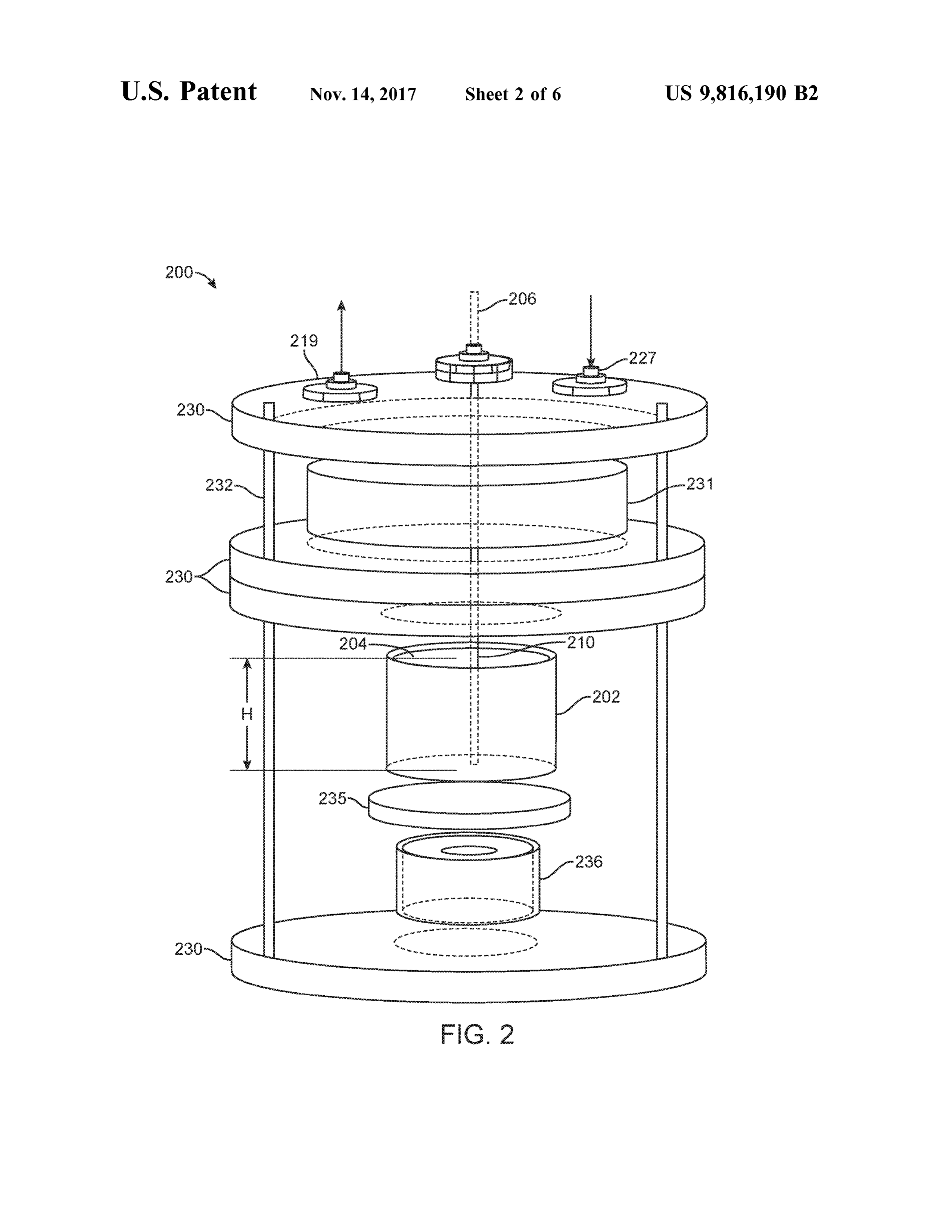
Further, cavitation and / or nulsed pulsed dielectric polarization may stock to a hollow chamber formed by a cylindrical wall be generated within the aqueous solution, whereby the wherein the chamber includes a cylindrical member dis - 10 action lowers the amounts of energy required to break posed within the chamber parallel to the wall; connecting a chemical bonds of the aqueous solution . positive terminal of a power supply via a positive reactive circuit to the chamber wall to form an anode ; connecting a BRIEF DESCRIPTION OF THE DRAWINGS negative terminalof the power supply via a negative reactive circuit to the cylindrical member to form a cathode; con - 15 FIG . 1 illustrates a system in accordance with exemplary necting the reactive circuits to an off-cycle chamber return load circuit; applying an input pulse DC voltage to the anode FIG . 2 illustrates aspects according to exemplary embodi and the cathode during an on portion of a duty cycle ; and ments;
extracting hydrogen gas from the conductive feedstock FIG . 3 illustrates a balancing circuit in accordance with wherein the reactive circuits and the off -cycle chamber 20 exemplary embodiments ;
return load circuit: process voltages returning from the FIG . 4 illustrates a method in accordance with exemplary chamber during an off portion of the duty cycle , the return embodiments ;
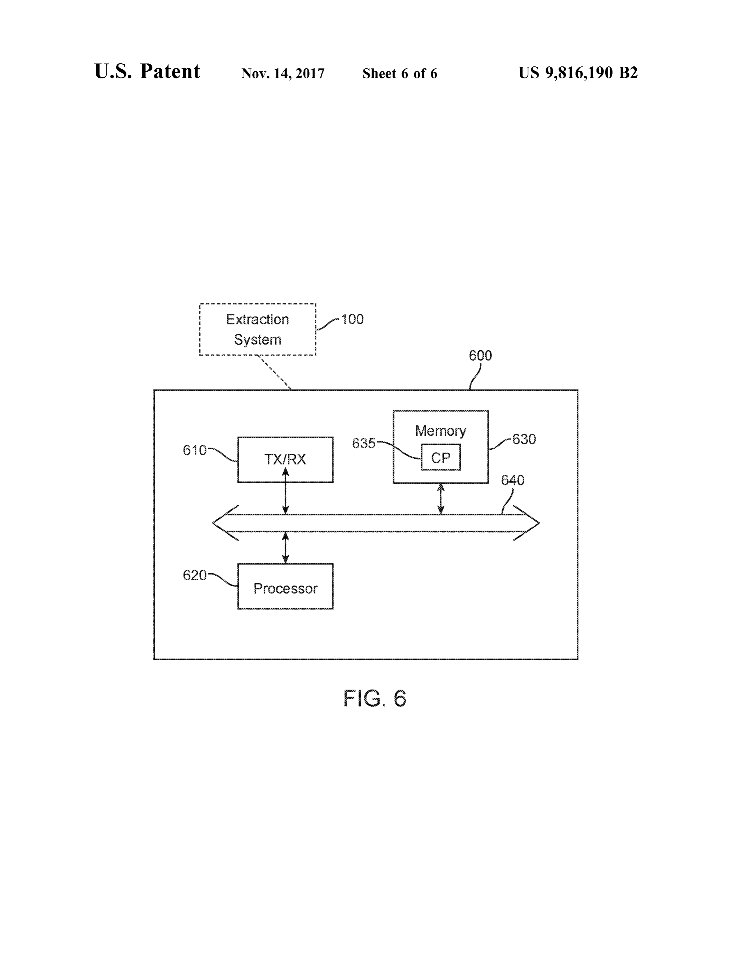
ing voltages resulting from an electro - chemical reaction in FIG . 5 illustrates a recirculation system of FIG . 1 ; and the chamber without surface reaction on the cylindrical FIG . 6 illustrates a computing device in accordance with member, and return the processed voltage to the chamber. 25 exemplary embodiments for operating the system of FIG . 1 . According to exemplary embodiments , a timed direct current (DC ) in the form of a pulse from a power supply is DETAILED DESCRIPTION applied in order to initiate an electronically reactive (i. e ., a reference to the science of reactive electronics ) electro - It should be understood that these embodiments are only chemical state - change in a saltwater liquid that has inherent 30 examples of the many advantageous uses of the innovative capacitive and impedance characteristics and values . By teachings herein . In general, statements made in the speci supplying the timed pulse with overpotential (i.e ., an elec - fication of the present application do not necessarily limit trical potential that overcomes the device ' s natural electrical any of the various claimed embodiments . Moreover , some potential, where the natural electrical potential is caused by statements may apply to some inventive features but not to dissimilar materials in the presence of saltwater ), the energy 35 others. In general, unless otherwise indicated , singular ele potential resident in the liquid is increased , chemical reac - ments may be in the plural and vice versa with no loss of tions in the liquid are catalyzed , and reactance characteris generality . The disclosed methods are intended to encom tics within the device are triggered (the term " device ” may pass methods practiced in the same order as disclosed , as also be referred to as a “ cell” and comprises the arrange - well is methods performing the disclosed steps in any order, ments, or a subset of the arrangements described herein ) . 40 unless otherwise indicated in the claims. These reactive characteristics generated by the device are As used herein , the singular forms “ a” " an ” and “ the” are used to modify and sustain the input signal during the off intended to include the plural forms as well, unless the phase of the duty cycle. These modifications generate and context clearly indicates otherwise . Additionally, the use of embed frequencies at the end of the pulsed input signal. “ or ” is intended to include " and / or ” unless the context Each cycle , on and off with wave frequency modification , 45 clearly indicates otherwise .
generates molecular hydrogen outgas as a result of one or “ Pulsed dielectric polarization ,” as used herein refers to more of the chemical reactions . The hydrogen gas is the use of varying electric potentials between the anode and removed from the system . cathode to create localized polarization of the fuel or feed Further, according to one aspect, upon removal of the stock components near the surface of the cathode. overpotential supply , there is an electrical discharge from the 50 “ Electrolysis ," as used herein , refers to Applicants ' gen liquid through electrodes ofdissimilar materials as the liquid eral protocol for producing hydrogen and carbon dioxide , attempts to return to its original electrochemical state . How - but use of the term is not an admission that the process is ever, the extraction of molecular hydrogen and the presence equivalent to the conventionally understood term . Appli of sacrificial materials prevent a full reversal of the process cants have demonstrated herein that, for example , hydrogen during discharge. The electrical discharge is prolonged by 55 and carbon dioxide are produced by a modified electro sets of different reversing chemical reactions. chemical process that departs meaningfully from pure elec According to one aspect, the free electrons discharged by trolysis. However, the term “ electrolysis ” is sometimes used the liquid and device are specifically directed to and cap - to refer in shorthand to the modified electrochemical hydro tured by electrolytic capacitors that are polarized to match gen production process described herein . the device and to provide a sink for those electrons. There is 60 As described further herein , at least one embodiment is a no ground potential in the system . The charged capacitors cell design comprising a coaxial outer electrode cylinder supply energy that produce modified waveforms with an with a given inner diameter and solid rod center electrode inherent set of frequencies governed by the reactive values with a given outer diameter. A radial ratio of 25 : 1 is within the device . During the time comprising the off-cycle maintained determining electrode separation distance within (i.e. off phase of the duty cycle ), unspent energy is available 65 the cylinder . Materials used in the cell chamber design and to assist the next application of overpotential and to com - in the conductive fluid (i.e ., feedstock ) composition play plete a duty cycle. critical, interdependent roles in the electrochemical process
Page 11scan →
(including sacrificial material processes). Alterations of the frequencies stating at 1 to 5 mHz; and ( iii ) a high frequency cell materials and chemical fluid mix change the type and range starting at 11 to 17 mHz.
intensity of reactions , and in turn determine outgases pro The unique set of frequencies are imposed on the input duced, production flow rates of the outgases, and relative pulse wave within a nanosecond of the beginning of the off composition ratios of the outgases . Combinations of mate - 5 portion or off phase of the duty cycle . The signals corre rials and fluids are therefore selected based on desired sponding to the unique set of frequencies are captured in the chemistry , outputs , and intensity of electrochemical reactiv electronic balancing circuit, amplified and fed back into the ity . cell interior (i. e . chamber ). As such , they are introduced into For example , it has been shown that the use of a graphite the fluid which assists in extending the time increment of the anode, a tungsten cathode , and saltwater fluid yield primar- 10 input cycle during the off period while activating the desired ily hydrogen gas. The bulk of the oxygen remains molecu - chemical reactions achieving the type of outgas release larly retained in the device either by means of alternative desired . These frequencies carry a distinctive wave shape fluidic reactions or by means of an oxidation reaction within that has a positive polarity in relationship to the input pulse the chamber wall . A small amount of carbon dioxide gas is zero reference . The energy in the form of frequency and also produced . 15 wave shape continues for multiple microseconds after the Regarding the input signals and circuitry , in at least one input pulse is in the off sequence . These wave shapes and embodiment, the circuit design , capacitive cell chamber frequencies are related to the capacitive and impedance rated design , and chamber fluid (i.e ., feedstock ) are integral parts value of the balancing circuit that are related to the chamber of an electrochemical circuit design . The cell chamber discharge sequence or flux phase . design is based on the 25 : 1 ratio , described herein . Once 20 The chamber fluid is a solution of water, salts and other loaded with the chamber fluid , the cell chamber will have a trace chemicals . The solution design and the cell design desired capacitive value in the range of 47 to 4 ,700 micro - require a complementary input signal of a particular timing, farads with a balance impedance circuit in the range of 1 to frequency as described above. Seawater with minimum 1, 000 microhenries. Electronic components are used in the filtration to remove particulate matter or deionized water input circuit to adjust these values during operation . Elec - 25 treated with a chemical base in order to resemble seawater tronic component polarity is critical to the overall operation may be used for example . This signal is used to set up the in that component polarity placement governs the direction initial conditions within the reactive chamber. During the of electron flow during the on and off phases of the input input signal' s off sequence , the chamber energy reacts with pulse cycle , respectively, in relationship to chemically gen the custom electronic balancing circuit to complete the erated energy return of the chamber . The cell chamber and 30 desired reaction . Energy supplied by the chamber chemical fluid are not treated as an end -load to the electronic input reaction also provides for greater electronic efficiency in the signal, but rather as complementary, electronically reactive generation of the desired output gases such as molecular components , wherein functional reactance and total circuit hydrogen .
design function is triggered by the input pulse . The cell Certain illustrative , non - limiting aspects according to chamber stores and then generates energy in engineered 35 exemplary embodiments are schematically depicted in FIG . waveforms during its off- cycle discharge or flux phase . The 1 . As illustrated in FIG . 1 , an arrangement 100 forms a energy released during this flux phase , changes the chem - hydrogen and carbon dioxide production arrangement or istry in the capacitive cell producing gas bubbles within the system . The arrangement 100 includes a first member 102 . fluid . An example of one such gas produced is molecular According to one illustrative embodiment, the firstmember hydrogen . 40 102 is defined by walls formed from any suitable material. According to an exemplary embodiment, the cylindrical The hollow cylindrical member 102 may act as a container electrode setup and input signals and circuitry described for a fluid material 104.
above functions as follows: first, an intermittent pulsed DC Any suitable fluid material 104 may be used such as an input signal of a given power level, time sequence , and aqueous-based feedstock comprising seawater. According to amplitude, is supplied to a custom -designed electronic 45 further optional embodiments , the feedstock may have com power -balancing and pre - conditioning circuit. The pulsed positions as described in U . S . patent application Ser. No . signal is then fed into the cell interior and into the fluid . The 13 / 170 , 132 , the entire contents of which is incorporated pulsed DC input signalhas a base frequency range of 1 to 10 herein by reference.
kHz. This base frequency is set to an optimum frequency The arrangement 100 may further include a secondmem during operation within the range given based on the 50 ber 106 disposed within the first member 102 . According to required off-timing increment of the sequence for a desired one illustrative embodiment, the second member 106 is in chemical reaction . The pre - conditioning circuit governs and the form of a solid cylindrical member formed from any balances (i ) the input amplitude with (ii) the cell chamber ' s suitable material. According to further optional aspects , the reactive power amplitude , and then returns excess energy second member 106 is disposed concentrically or coaxially produced by the cell during the end period of the off phase 55 with respect to the first member 102 .
of the duty cycle to the chamber . According to exemplary embodiments , when the first Electronic balancing of the input signal with the returned member 102 and the second member 106 are formed as chamber energy response facilitates a unique set of frequen - cylindricalmembers , with the second member 106 disposed cies and wave shapes governed by the chamber ' s electro - within the first member 102 , the members can be provided chemical characteristics . These characteristics include the 60 with any suitable size or dimensions. The first and second chamber' s unique chemical-dependent discharge pattern . members may be provided with radii such that the ratio of The chamber 's chemical and reactive energies discharge the radius of the second member relative to the first member resembles a straight line DC amplitude without time is approximately 1 :25 .
sequence or frequency. The set of frequencies embedded The arrangement 100 may further include a power supply within the chamber 's reactive energy is unique and falls 65 108 in electrical communication with both the firstmember within three distinctive ranges : (i) a low set of frequencies 102 and the second member 106 , as indicated by the broken starting at 650 kHz to 950 kHz; ( ii ) a mid - range set of lines appearing in FIG . 1 . Any suitable means of electrical 12 connection can be utilized for this purpose . When connected making up each molecule 's composition . Collisions between with a power source , as illustrated in FIG . 1 both the first molecules caused by the rotation cycles also cause chemical member 102 and the second member 106 can be formed reactions.
entirely from an electrically conductive material. Alterna Magnetic field flux is caused both during the on phase (or tively , at least the inner surface of the first member 102 5 on portion ) of the pulse duty cycle as the electrical and exposed to the feedstock 104 is formed from an electrically corresponding magnetic fields form and again during the conductive material, and at least the outer surface of the opposite effects of the off phase of the duty cycle. As the second member 106 exposed to the feedstock 104 is formed magnetic filed forms during the on phase of the duty cycle , from an electrically conductive material. The remaining molecules in fluid 104 with dipolar moments (such as water ) portions of the first and second members 102 and 106 " align to the field . The molecular orientations of fluid 104 in respectively can optionally be formed from a non - conduc - the chamber adjust further as the fluid molecules are pushed tive material. through magnetic lines of force y thee forced recirculation of According to certain embodiments, the power supply 108 fluid 104 through the chamber of member 102 . is configured so as to electrically connect at least the 1s During the off phase of the pulse duty cycle , the electrical conductive portion (such as the inner surface for example ) of field changes to re the lagging reactive electrical current the first member 102 to a positive terminal thereof, and to dynamics inside the chamber and the magnetic field changes electrically connect at least the outer surface of the second accordingly. In general, molecular alignments within fluid member 106 to the negative terminal thereof. Thus, the first 104 will revert back to their mean state of increasingly member 102 forms an anode, and the second member 106 20 random molecular orientation or polarity until the next on forms a cathode. As a result, an electrical potential is created phase of the duty cycle.
between the inner surface of the cathode 106 and the outer Furthermore, during the off phase of the duty cycle , the surface of the anode 102 . electrical discharge effects of the chamber are slowed using The wall of chamber 102 may be composed of graphite an electronic flow control circuit . The effect of the flow and is positively charged . The wall may have a height of 25 control circuit is no regulate the deterioration of the elec approximately 50 mm . The chamber may have a diameter of trical and magnetic fields, reducing and prolonging the approximately 25 mm (i.e. radius of 12.5 mm ). The second magnetic flux , and thereby regulating the molecular rotation member 106 may be composed of tungsten and is negatively of vector velocity of the dipolar fluid molecules in the charged . In such case , the tungsten rod may have a diameter chamber of approximately 1 mm and a height or length of approxi- 30 A change in magnetic field has its own second -order mately 50 mm . A conductive fluid (such as water with effect. When an EMF is induced by magnetic flux , the sodium chloride and other trace chemicals) may be supplied polarity or current direction of the induced EMF produces an to the chamber void (i.e . between the rod and the chamber opposing current magnetic field flux component. The wall). This fluid may form a conductive path from the outer 36 induced magnetic field inside a loop of wire acts to keep the chamber wall to the inner chamber rod . The fluid and with 35 magnetic mnd flux in the loop constant.
chamber combination form a non - ideal capacitor with capacitive and inductive values . The net magnetic field of the chamber is very complex . The positive terminal of power supply 108 is connected The chamber magnetic field is designed to have a strong via positive reactive circuit 150 to chamber 102 . The nega - influence on molecular structure of the conductive fluid tive terminal of power supply 108 is connected via negative 40 within the chamber, assisting in the molecular separation reactive circuit 160 to the second member 106 . Both reactive and energy harvesting within the chamber. The conductive circuits 140 and 150 may also be connected to an off cycle fluid within the chamber is in constantmovement due to the chamber return load circuit 170 . The reactive circuits and the use of an active recirculation system . The input pulse to the off cycle chamber return load circuits are described further chamber initiates a magnetic field , aligned in relation to the below with reference to FIG . 3 . The power supply connec - 45 flow of input electrons into the chamber . Initial magnetic tion to chamber 102 provides electron flow to chamber 102 . field lines are cut by the conductive fluid in motion . The The chemical energy within the chamber interior provides a motion of the fluid through the chamber increases the reverse polarity electron flow . This reverse polarity electron magnetic field strength within the chamber. Specifically, the flow may also be referred to as an inductive electromotive motion of the fluid within the influence of the initial input force (EMF). At the time of electron flow , a magnetic field 50 induced magnetic field ( input -cycle ) yields additional mea in a predictable order is generated . Prior to electron flow sureable energy. The additional energy is returned from the sequence, the polarities of the molecules in the chamber are chamber via the return leg of the electronic circuit , in a chaotic order. Each molecule within the fluid has an The energy returned via the return leg of the circuit has individual polarity orientation at the start of the sequence . frequency values. The energy frequencies are carried in Once energy is supplied to the chamber and electron flow is 55 waves shaped dynamically by the chamber. These waves are initiated , molecular orientation changes in response to a new captured in the return electronic loop and then re -applied to magnetic field polarity within the chamber. The pulsed the chamber in a reverse polarity discharge- feedback - cycle energy causes the magnetic field to rise and collapse with to regulate a desired molecular reset -cycle of the conductive each on -and -off sequence of the timing circuit. The rise and fluid and to assist with molecular separation within the collapse of themagnetic field also causes molecular rotation . 60 conductive fluid . This process enables molecular separation Molecular rotation , during the rise and collapse of the to occur at lower energy states within the chamber. magnetic field order within the chamber, generates addi- During the off phase of the duty cycle , electricity still tional forces in the form of vector and velocity values. These flows due to the aforementioned induced energy return (i.e. rotations cause respective nano - scale distances to increase reactance ) of the chamber. The chamber 's unique signature and decrease between atoms. Rotational effects during the 65 return loop and net reactance modifies the off - cycle molecu on and off portions of the impulse cycle reduce the strength lar polarity reset- cycle sequence . Excess return loop energy of the atomic bonds to aid in the separation of the atoms that is not attenuated during the off- cycle is added to the next 13 on phase of the duty cycle . Such addition modifies (i.e. The blocking diode section 320 prevents voltages constructively interferes with ) the next on phase of the duty returned from the chamber from interfering with the input cycle . signal. The diodes within 320 isolate the downstream circuit The chamber 102 and member 106 ( rod ) arrangement of during the off cycle while the reactive part of the circuit is FIG . 1 forms a unique shape that allows for uniform and 5 in recovery . The isolation from the input assists with col non -uniform lines of magnetic force formation . These mag - lecting and manipulating the energy being returned from the netic fields follow Faraday ' s law of electromagnetic induc reaction chamber. The reaction chamber has frequency val tion with the exception of the molecular magnetic fields u es embedded in the DC return voltage . The return voltage influence . The molecular magnetic fields are influenced may have an amplitude ranging from 0 .9 VDC to 4 .2 VDC during the on state of the input cycle causing a polarity shift 10 while the input voltage average amplitude based on the pulse at the molecular level. These molecular magnetic fields form width may range from 0 .7 VPDC to 1 .4 VPDC . a counter electromotive force (EMF) which may be mea The positive reactive balance section 330 sets and bal sured at the electrodes in the form of a voltage differential. ances impedance and capacitance within the reaction cham These voltage differentials are at least 0 . 9 VDC before initial ber. The reaction chamber has varying internal restive energy is applied and at least 3 .4 VDC after energy has been 15 (ohmic ) and voltage amplitude values . The variation may be applied . Lenz 's law of opposite or opposing magnetic field based on electrolyte conditions that the input pulse has to polarity will apply to this state of the chamber operation . overcome. The capacitance assists in storage of energy that These magnetic fields form a 360° process area around the is released at the appropriate time to assist in the over center cathode material just off the surface where gas potential that is required to drive the reaction cycle within formation takes place . These magnetic fields form a similar 20 the chamber. The impedance balances the circuit while area just off the surface of the anode material although no providing lower amplitude and steady state current draw gas formation is visually observable in this area of the during the on cycle . This portion of the circuit also provides chamber. Therefore , no surface reaction takes place either to imbalance the return circuit. The positive input to the along (i) the surface of the chamber walls (anode ) or along reaction chamber is connected to this section of the circuit. (ii) the surface the rod in the center ( cathode ). This has been 25 The negative reactive balance section 340 sets and bal validated by a lack of deterioration of the cathode and the ances impedance and capacitance within the reaction cham anode . Furthermore , in simulations where the center elec - ber on the negative return . The chamber does not have the trode projected below the chamber and was not subjected to same zero value at ground as the input pulse section . The the insulation ( such as insulation 110 at the top of chamber chamber is not grounded in the conventional sense of circuit 102), deterioration of the center electrode was evident. 30 design . The chamber, through the circuit design , establishes The chamber design when filled with conductive fluids a zero reference point unique to the reaction chamber. This form a very reactive electronic circuit. As described above , zero reference point is used during the reset/return operation a variety of forces are interacting with each other. These of the reaction chamber during the off cycle . The internal include electrochemical and magneto -hydrodynamic forces. resistive ( ohmic ) and voltage amplitude that the input pulse A chamber control circuit ( comprising positive and negative 35 has to overcome is assisted with the section similar to the reactive circuits 150 and 160 of FIG . 1 ) is used for imped positive reaction circuit. The values for impedance and ance matching and capacitive balancing. Balancing the capacitance are different from those on the positive side. The control circuit accomplishes multiple functions. These func - capacitance assists with storage of energy that is released at tions include , but are not limited to : electronic circuit the appropriate time to assist in the over potential required efficiencies, lowering reactive circuit current demand and 40 to drive the reaction cycle of the chamber. The impedance proper frequency management. The control circuit is balances the circuit while providing lower amplitude and designed to direct a pulsed DC input signal at a given base steady state current draw during the on cycle . This section of pulse frequency to the reaction chamber. The circuit design , the circuit also imbalances the return circuit. The negative as illustrated in FIG . 3 includes a plurality of sections. The input to the reaction chamber is connected to this section of circuit assists the reaction chamber in very high efficiency 45 the circuit.
levels of gas production while limiting input voltage ampli - The off cycle chamber return load section 350 is in reverse tude and current . polarity to the pulsed dc input. This section of the circuit In circuit 300 of FIG . 3 , the pulsed DC section 310 may consists of a light emitting diode (directional load ) in reverse correspond to power supply 108 of FIG . 1 and supplies a polarity that completes the circuit through a set of reversed direct pulse at the input stage of the circuit . The pulse may 50 polarity electrolytic capacitors . They act as a secondary load have amplitude ranging from 0 VPDC to 50 VPDC . Varia to the chamber 's reset reaction during the off cycle and thus tion on the input amplitude may be based on desired restricting the electron discharge flow rate . The energy chamber performance . The pulsed DC section provides for stored in the positive and negative capacitor banks is then adjustments in the pulse width or duty cycle based on a allowed to interact with the chamber reset energy. This desired chamber performance in gas type and generation 55 interaction assists in establishing a set of frequencies that are quantity . The pulse width may be set for a desired length in generated by the molecular reset function within the cham the on and off cycle timing. A combined on and off cycle ber. These frequencies are established on demand during the form one full cycle. The timing of the duty cycle establishes off cycle . At this point all input energy is in off position of a base frequency for the pulsed de signal . This pulse base the cycle. All energy that is in use at this time is either from frequency can range from 100 Hz to 10 kHz for example . 60 stored energy potential in capacitor banks or from the energy The timing of the input pulse is adjusted in such a manner created in the chamber pushing back into the circuit. Oscil as to maintain an optimized rise time while maintaining the loscope monitoring during the off cycle of the input pulse least amount of time sweep during the rise time. The duty verifies the interaction from the chamber and system control cycle can vary from 10 - 13 % ( in the on cycle versus the off circuit . The blocking diode section 320 prevents any flow of cycle time) for example. The duty cycle or timing is set for 65 electrons from reaching the pulsed DC section 310 . This desired chamber efficiencies versus gas type and generation limits interference with the pulsed dc input signal when the quantity. next on cycle is initiated .
Page 14scan →
Alternatively, the cathode can be formed 106 from base constituent components . The acoustic and electromagnetic material, such as graphite , provided with a sheath or layer of sensors can provide signals for maintaining optimized platinum thereon . According to a further option , the cathode hydrogen output. Other environmental sensors provide the 106 can be formed from tungsten carbide , or a similar ability to maintain optimal operating conditions. Sensors tungsten alloy. 5 monitoring the output of separated gas can facilitate , inter According to exemplary embodiments , the length of the alia , monitoring of the efficiency of the gas separation cathode exposed to the feedstock 104 is approximately equal process.
to the height H of the anode. As illustrated in FIG . 1 , the When used as a system to extract hydrogen and carbon actual length of the cathode 106 may extend above the dioxide from an aqueous feedstock , power supply 108 height of the anode 102. In such a case, the portion of the 10 causes cathode 106 to be negatively charged and anode 102 cathode 106 that extends above the height of the anode 102 can be electrically insulated from a portion in communica todifference be positively charged . As a result, an electrical potential is created between cathode 106 and anode 102 .
tion with the feedstock . This can be accomplished by any The electrical potential difference polarizes the ions close to suitable technique, such as by disposing a collar of insulat the ing material 110 around the cathode 106 , as also illustrated 15 ne cathode . An amount of current is also created as the in FIG . 1. electrochemical reaction proceeds. These actions on the According to exemplary embodiments , the power supply feedstock 104 cause formation of hydrogen and carbon 108 used to power at least the anode 102 and cathode 106 is dioxide. The gas extraction system removes the gases out of configured and arranged to provide a direct current (DC ) container 102 for further use ( shown by arrow 142 ) , such as supply of power. According to one optional variation of the 20 to provide fuel for hydrogen fuel cells, to directly power an arrangement 100 , a DC power supply , having a plurality of engine of a transportation vehicle , or provide components channels , is used to power the anode 102 and a cathode 106 . for further chemical processes like a Fischer - Tropsch reac The efficiency of an anode/cathode -based system can be tion system . As feedstock 104 is consumed and the con markedly improved through manipulation of the power stituent gases are removed from the system 100, additional signals applied thereto . For example , according to exem - 25 feedstock can be added through an inlet ( e .g ., 119 ). plary embodiments, a power supply may be configured and Exemplary embodiments , as illustrated in FIG . 2 may arranged so as to produce electrical signals to the anode and include a stabilization platform having four rigid , noncon cathode ( e.g., 102 , 106 ). Power supply 108 produces elec ductive base plates 230 , a rigid , nonconductive tube 231, a trical signals to the anode and cathode. rigid , nonconductive plate 235 , a nonconductive , rigid tube The arrangement 100 may be optionally provided with a 30 236 , and a series of six stainless steel bolts 232 and feedstock recirculation system 118 . The recirculation system accompanying nuts, washers and spacers provide a frame 118 is schematically illustrated in FIG . 1 (and in FIG . 5 ) and work for a liquid - tight support structure. Two base plates it may have any suitable configuration evident to those 230 and the tube 231 form a fuel reservoir. The plate 235 skilled in the art based on the teachings provided herein . forms a base . The polycarbonate tube 236 provides support According to one illustrative example , the feedstock 104 35 between the base plate 230 and the plate 235 . Other elements passes through a first conduit 127 through a gas contractor shown in FIG . 2 have corresponding features as 100 - series 120, and into a fuel reservoir 122 . The feedstock is pulled elements in FIG . 1 such as , for example , cathode 106 / 206 . through a pump 124 and passed into a heat exchanger 126 , A method in accordance with exemplary embodiments is then returned into the container formed by the first member illustrated in FIG . 4 . A conductive feedstock is provided to 102 via a second conduit 119 . The reservoir 122 serves as a 40 the chamber at 410 . The positive terminal of the power preconditioning zone to maintain feedstock and catalyst supply is connected to the chamber wall via a positive concentrations at the desired levels , and may also provide a reactive circuit at 420 . The negative terminal of the power sensing point within the circulation system . The heat supply is connected to the cylindricalmember via a negative exchanger maintains a constant temperature . The closed reactive circuit at 430 . The reactive circuits are connected to nature of the system allows the selection and maintenance of 45 the off cycle chamber return load circuit at 440 . An input a particular selected operation pressure or range of pres - pulse DC voltage is applied to the anode and the cathode sures . during an on portion of a duty cycle at 450. Hydrogen gas The arrangement 100 may further comprise a gas collec - is extracted from the conductive feedstock at 460 . The tion arrangement or system 128 , as illustrated in FIG . 1 , may reactive circuits and the off cycle chamber return load circuit have any suitable configuration evident to those skilled in 50 process voltages returning from the chamber during the off the art based on the teachings provided herein . According to portion of the duty cycle and return the processed voltage to further illustrative and non -limiting examples , gas is pulled the chamber at 470 . The processing may include : balancing through conduit 127 and from the gas contactor 120 through impedance and capacitance within the chamber, preventing a cold trap 138 by vacuum pump 136 , which then pushes the the returning waves from interfering with signals being input gas through a flow meter 140 . According to further optional 55 to the chamber and returning the processed voltages to the aspects, the gas may be collected and utilized outside of the chamber.
illustrated system or arrangement 100 as indicated at ele Exemplary embodiments such as the process or method ment 142 . steps described above with reference to FIG . 4 may be Arrangements constructed according to exemplary implemented within a computer program that can be embodiments may further include a plurality of sensors (not 60 executed on a general purpose computer. An exemplary illustrated ) to monitor and control various aspects of the computer 600 such as that illustrated in FIG . 6 includes a arrangement are system . Such sensors may include one or a transceiver 610 , a processor 620 and a computer readable combination of sensors to monitor the electromagnetic envi- medium 630 . Transceiver 610 , processor 620 and memory ronment of the arrangement, the temperature of the system , 630 may be interconnected via a bus 640 . The computer the pressure of the system , the temperature of the heat 65 program may be stored in memory 630 . Computer 600 may exchanger, the acoustic environment within the system , and be connected to the exemplary system 100 of FIG . 1 to the concentration of the feedstock and/ or one or more of its perform the steps of FIG . 4 .
Page 15scan →
In one embodiment, in order for processor 620 to perform electrons try to repel each other and may contribute to the the steps illustrated in FIG . 4 ,memory 630 may comprise a lack of surface reaction along the tungsten rod . computer program (CP ) 635 with computer program mod Methods and techniques associated with the above ules which when run by the processor 620 causes the user described operation and functionality may include one or equipment 600 to perform all or some of the steps illustrated 5 more of: forming an arrangement comprising combinations in FIG . 4 . A plurality of sensors ( that monitor various aspects of any of the above-described features; transmitting electri of system 100 ) may provide data to the computer 600. cal signals to certain members of the arrangement in any of The production rates of hydrogen gas are dependent on the ways described previously herein ; generating a product the type of input supplied to the reaction chamber(s ) and the 10 any .of ( e . g , hydrogen ); and capturing and handling the product, in the ways previously described herein .
type conductive fluid in the chambers. The reaction chamber Other embodiments within the scope of the claims herein (s ) as described produce gas throughout a set spectrum of will be apparent settings. These settings such as pulsed DC width duty cycle, of the specificationto oronepractice skilled in the art from consideration of exemplary embodiments as amplitude of pulse and pulse base frequency are adjusted for disclosed herein . It is intended that the specification be desired levels of gas production versus desired efficiencies. 15 considered exemplary only, with the scope and spirit of the An efficiency in the levels of gas production is desirable . disclosure being indicated by the claims. Efficiency measurements are determined by comparing the In view of the above , it will be seen that the several amount of input energy used with the amount of energy advantages of the invention are achieved and other advan released in the form of Hydrogen gas . Based on a given tages attained . As various changes could be made in the atmospheric pressure and temperature , a value may 20 above methods and compositions without departing from the obtained . Example obtained At standard atmospheric pres scope of the invention , it is intended that all matter contained sure and temperature at sea level , approximately 6 .06 mil - in the above description shall be interpreted as illustrative liliters of hydrogen gas equals to one ( 1 ) watt of energy and not in a limiting sense.
An efficiency greater than 1 to 1 in hydrogen production Any numbers expressing quantities of ingredients, con is desirable . The unique chamber design and customized 25 stituents , reaction conditions, and so forth used in the electronic circuitry as described herein facilitate obtaining specification are to be understood as being modified in all such efficiency . Such efficiency has been realized with an instances by the term “ about.” Notwithstanding that the input setting of 0 .73 VPDC at 0 .0387 amps. These settings numeric al ranges and parameters setting forth , the broad equal to 0 . 28 watt . At this wattage setting, in order to achieve scope of the subject matter presented herein are approxima a 1 to 1 production rate of hydrogen gas , a quantity of 1 .71 30 tions, the numerical values set forth are indicated as pre milliliters of gas has to be produced . cisely as possible . For example , any numerical value may In the system and methods described herein , quantities of inherently contain certain errors or inaccuracies as evident Hydrogen gas exceeding 3 .42 milliliters have been realized from the standard deviation found in their respective mea This production rate exceeds the 1 to 1 rate by a factor of 2 . surement techniques. None of the features recited herein That is, the efficiency achieved is 2 to 1 (3 .42 = 1.71 * 2 ). In 35 should be interpreted as invoking 35 U . S .C . $ 112 , 6 , unless the exemplary systems, for one watt of input energy , two the term “means” is explicitly used .
watts of energy in the form of hydrogen gas is achieved ( a level of 200 percent). PRIORITY CLAIM The efficiency and hydrogen production rates can be varied through different input settings coupled to the cir - 40 The present disclosure claims priority to Provisional cuitry as discussed . Efficiencies greater than 3 have been Application No . 62/091 ,702 filed on 15 Dec . 2014 , the achieved . A production rate greater than 5 milliliters per subject matter of which is incorporated herein by reference . cell/ chamber at efficiencies greater than 2 have been achieved repeatedly . 1 . A system for extracting hydrogen from a conductive Salt bridges are used in electrolysis to act as an electrical 45 fluid comprising:
conductor between the two electrodes in an electrolytic a hollow chamber defined by a cylindrical wall ; fluid . When using sea water, a salt bridge can sometimes a cylindrical member disposed within the chamber par form between the two electrodes if they are relatively close allel to the wall ;
to each other. This would then reduce the production area a mechanism for providing conductive feedstock to the and eventually form a short circuit between the electrodes . 50 chamber ;
By constantly recirculating saltwater as described above , as a second mechanism for re - circulating the conductive well as the greater distance between the electrodes , such salt feedstock through the chamber ; bridge formation has been avoided . a power supply having a positive terminal connected via The large difference in the surface areas of the electrode a positive reactive circuit to the chamber wall to form materials causes a concentration or electron buildup at the 55 an anode and a negative terminal connected via a cathode. This may result from the large area of the anode negative reactive circuit to the cylindricalmember to having electrons leaving and moving towards the small form a cathode, the power supply providing an input cathode. The area around the cathode would have to become pulse DC voltage for an on portion of a duty cycle ; and very saturated as the negative charged electrons try to find an off cycle chamber return load circuit connected to the a pathway to the cathode to leave the chamber. 60 positive and negative reactive circuits wherein the Electrons are being emitted from a full 360 degrees of the reactive circuits and the off cycle chamber return load chamber walls along the length of the 50 mm chamber circuit :
height that form the positively charged anode. As the elec process voltages returning from the chamber during an trons flow toward the center (i.e . the negatively charged off portion of the duty cycle , the returning voltages cathode), they are forced into a continuing decreasing area . 65 resulting from an electro - chemical reaction in the This forms an area of electron saturation just off the surface chamber without surface reaction on the cylindrical of the cathode . Electrons have the samenegative charge . The member , and 16 return the processed voltage to the chamber, wherein connecting a negative terminal of the power supply via a the chamber releases hydrogen gas . negative reactive circuit to the cylindrical member to 2 . The system of claim 1 wherein the feedstock is sea form a cathode;
water. connecting the reactive circuits to an off cycle chamber 3 . The system of claim 1, wherein the cylindricalmember 5 return load circuit;
is formed from Tungsten . applying an input pulse DC voltage to the anode and the cathode during an on portion of a duty cycle ; and 4 . The system of claim 1, wherein the walls are formed extracting hydrogen gas from the conductive feedstock from Graphite . wherein the reactive circuits and the off cycle chamber 5 . The system of claim 1 , wherein a ratio of a radius of the return load circuit:
chamber to a radius of the cylindrical member is 25 : 1. process voltages returning from the chamber during an 6 . The system of claim 1 , wherein a diameter of the off portion of the duty cycle , the returning voltages chamber is 25 mm . resulting from an electro - chemical reaction in the 7 . The system of claim 1 , wherein a diameter of the chamber without surface reaction on the cylindrical cylindrical member is 1 mm . member , and 8 . The system of claim 1, wherein a height of the wall1 .is 15 13 return . The the processed voltage to the chamber.
method of claim 12 , wherein the feedstock is 50 mm . seawater.
9. The system of claim 1 , wherein the chamber is formed 14 . The method of claim 12 , wherein the anode and from a block Graphite, the block including a plurality of cathode are cylindrical, the cylindrical cathode being dis chambers with each chamber having a respective cylindrical 20 posed symmetrically within the cylindrical anode. Tungsten rod. 15 . Themethod of claim 12 , wherein a ratio of a radius of 10 . The system of claim 1 , wherein only the inner surface the cathode to a radius of the anode is approximately 1 : 25 . of the anode is in communication with the feedstock . 16 . The method of claim 12 , further comprising forming 11 . The system of claim 1 . further comprising a plurality the anode from graphite and forming the cathode from of sensors for monitoring activity within the system . 25 aun 12 . A method for extracting hydrogen from a conductive has17a. cylindrical
The method of claim 12 , wherein the cylindrical anode inner surface and a cylindrical outer sur fluid comprising:
providing conductive feedstock to a hollow chamber is in communicationthewith face , wherein only inner cylindrical surface of the anode the feedstock .
formed by a cylindrical wall wherein the chamber includes a cylindrical member disposed within the 3030 duty18 .cycle The method of claim 12 , wherein the on portion of the is less than 13 % of the duty cycle .
chamber parallel to the wall ;
connecting a positive terminal of a power supply via a circulating 19 . The method of claim 12 , further comprising re positive reactive circuit to the chamber wall to form an the fluid through the chamber. anode; * * * * *
Provenance
- Collection
- Patents citing this work
- Original assignee
- Joi Scientific Inc
- Pages
- 16
- Method
- pdftotext (the PDF's own text layer) + pdftoppm 300dpi page scans
- Patent office record
- patents.google.com →
- Source
- Google Patents citing-documents table
- Inventors
- Robert Louis Koeneman; Traver Hall Kennedy; Joi Scientific Inc
- Published
- 2017-11-14
- Transcribed from
- patentimages.storage.googleapis.com →