

patent · USRE31678E
System for collecting solar energy
18 September 1984
Text
Page 1bibliographic recordscan →
United States Patent (19) (11) Ochiai (45)
(54) SYSTEM FOR COLLECTING SOLAR
ENERGY
76 Inventor: Tsurunosuke Ochiai, 3.169-6,
Saga-ken, Japan, 847
Related U.S. Patent Documents
Reissue of:
(5) Int. Cl................................................. GO2B 5/16 52 U.S. C. ................................. 350/96.24; 126/417;
3,780,722 2/1973 Swet .................................... 126/45
4,201,197 5/1980 tismer ................................ 126/45
Reissued Date of Patent: Sep. 18, 1984 4,247,165 l/1981 Versluis ............................ 350/96.27 Primary Examiner-John D. Lee
Attorney, Agent, or Firm-Sprung, Horn, Kramer &
Woods
A system for collecting solar energy which comprises a thin faceplate made of a large number of optical fibers having respectively a diameter ranging from 0.5 micron to 2.0 micron tied up coherently in a bundle vertically to the plane of the faceplate, and a means for focusing the rays departing from the optical fibers of the face plate.
The faceplate enables to let solar rays entering into the optical fibers from all directions within the numerical aperture of the fibers pass through the fibers to let rays parallel to the principal axis of the faceplate depart from the fibers. Accordingly, the system enables to collect solar energy with a high collecting efficiency with no special means for strictly following the sun.
FIG. 4 is a vertical sectional view of a system of this invention, where 1 is faceplate, 2 optical fibers compos ing the faceplate, 3 concave parabolic mirror, 4 convex parabolic mirror, 9 a bundle of optical fibers for trans mission.
14 Claims, 7 Drawing Figures
Drawings
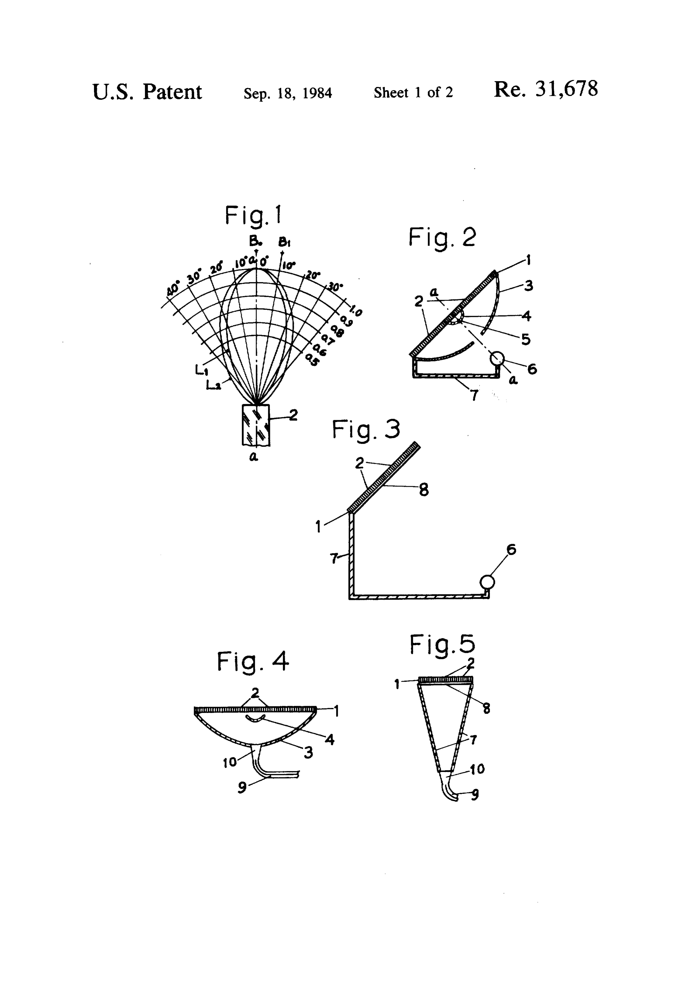
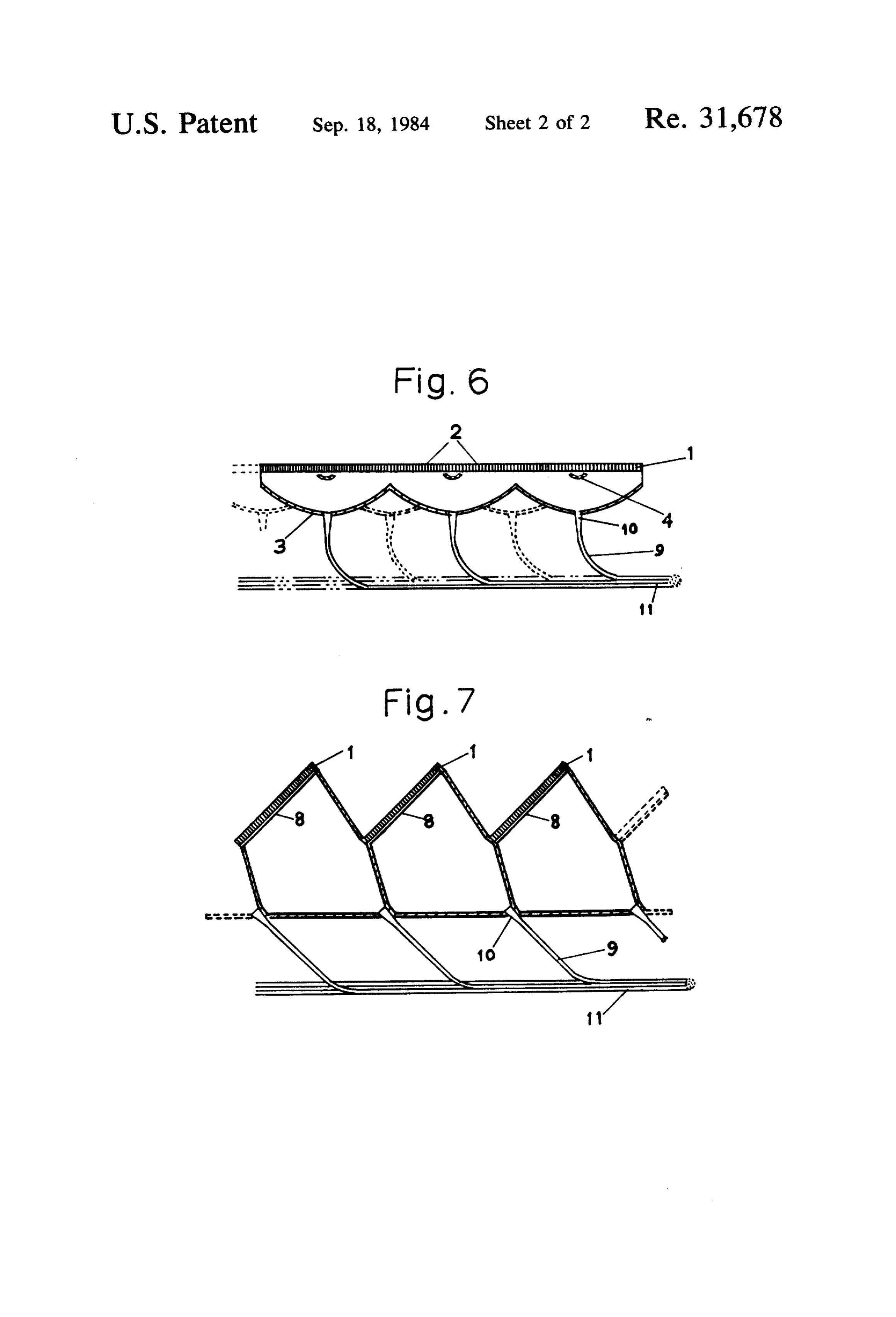
FIG. 1 shows directivity patterns based on Fraun hofer diffraction which is formed when beams of paral lel light depart from the aperture of an optical fiber along the principal axis of the fiber.
FIG. 2 is a vertical sectional view of a system of this invention which as a focusing means consisting of two parabolic mirrors.
FIG. 3 is a vertical sectional view of another system of this invention which has a focusing means of a Fres nel lens.
FIG. 4 is a vertical sectional view of a system of this invention which has a focusing means consisting of two parabolic mirrors, and a means for transferring the fo cused energy.
FIG. 7 is a vertical sectional view of a system of this O invention which is compounded with a number of unit systems of FIG. 5.
Page 2drawing sheetscan →
Page 3drawing sheetscan →
Page 4scan →
System for collecting solar energy
Matter enclosed in heavy brackets appears in the original patent but forms no part of this reissue specifica tion; matter printed in italics indicates the additions made by reissue.
Background of the invention
1. Field of the Invention
This invention relates to a new system for collecting the radiant energy of sunlight.
2. Description of the Prior Art
Heretofore, several systems for collecting the radiant energy of sunlight have been proposed. As an example seen in a solar-electric power plant or a solar furnace, sunlight is concentrated, to yield a high temperature, on a receiver by a large number of mirrors designed to follow the sun, or so-called heliostats, wherein each mirror must be individually moved by clockwork for strictly reflecting the solar rays into a fixed direction to the receiver, so that it is inevitable for the system to become very complicated in a large scale. A unit collec tor such as giant parabolic mirror on Fresnel lens as another example must be also designed to strictly follow the sun, otherwise the incident solar rays can not focus on one point, so that the efficiency for collecting solar energy lowers markedly. Many attempts for improving the follow-means have been made, but any of those is still complicated and expensive. We have now found that collecting the radiant energy of sunlight with a considerable high efficiency can be accomplished with no special follow-means.
Summary of the invention
An object of this invention is therefore to provide a system for collecting the radiant energy of sunlight with a considerable high efficiency with no special means for following the sun.
Another object of this invention is to provide a simple and cheap collector of solar energy.
Other objects will be apparent from the following description.
Thus, this invention relates to a system for collecting the radiant energy of sunlight which comprises a face plate for receiving the parallel rays of sun which is a thin plate made of a large number of optical fibers hav ing respectively a diameter ranging from 0.5 micron to 2.0 micron tied up coherently in a bundle vertically to the plane of the faceplate, and a means for focusing the parallel rays departing from optical fibers of the face plate to concentrate the radiant energy outside the sys ten,
Brief description of the drawings
FIG. 1 shows directivity patterns based on Fraun hofer diffraction which is formed when beams of paral lel light depart from the aperture of an optical fiber along the principal axis of the fiber.
FIG. 2 is a vertical sectional view of a system of this invention which as a focusing means consisting of two parabolic mirrors.
FIG. 3 is a vertical sectional view of another system of this invention which has a focusing means of a Fres nel lens.
FIG. 4 is a vertical sectional view of a system of this invention which has a focusing means consisting of two parabolic mirrors, and a means for transferring the fo cused energy.
FIG, 5 is a vertical sectional view of another system of this invention which has a focusing means of a Fres nel lens and a means for transferring the focused energy. F.G. 6 is a vertical sectional view of a system of this invention which is compounded with a number of unit systems of FIG. 4.
FIG. 7 is a vertical sectional view of a system of this O invention which is compounded with a number of unit systems of FIG. 5.
Detaled description of the
Preferred embodiments
15 The most essential feature of this invention consists in the faceplate. The faceplate is a plate made by a large number of optical fibers tied up coherently in a bundle vertically to the plane of the faceplate. Each diameter of the optical fibers is selected from a range of 0.5 micron to 2.0 micron, which is the gist of the faceplate. Thick ness of the faceplate is not essential, but may be in a range of three to ten millimeters.
This faceplate works very effectively. According to this faceplate, the rays departing from each optical fiber 25 of the faceplate have always a certain intensity compo nent along the principal axis of each optical fiber, so that all the rays departing from all optical fibers of the faceplate has always some intensity component along the direction of principal axis of the faceplate, when 30 ever solar rays enter into the faceplate from a direction being within about the numerical aperture of the optical fiber of the faceplate. Hence, numerical aperture stands for sin Sevilla wherein 6 represents angle of deviation from principal axis, in represents refractive 35 index of the optical fiber, and n2 represents refractive index of the material surrounding the optical fiber. The value of numerical aperture varys depending on n1 and n2, but is exemplified as about sin 39. Namely, the faceplate of this invention can produce, from all of its under surface, rays having a certain intensity as a com ponent parallel to the principal axis of the faceplate, whenever solar rays enter into the faceplate from the direction area which is formed by a cone formed by the revolution around the principal axis of the line having 45 an angle of about 39 between the line and the principal axis of the faceplate. The parallel rays produced can be easily focused by a fixed single means for focusing par allel rays having a definite direction. Namely, this face plate enables to obviate the necessity of follow-means of 50 the sun.
The reason why optical fibers work so effectively in the diameter range of 0.5-2.0 micron, will be given by the principal of Fraunhofer diffraction and the principle of reversibility of light-path. The illustration will be 55 easier, when the incident rays are rays having a single wave length. The basic idea of this invention is that each diameter of optical fibers is selected from the di ameter not larger than 1.22A, A is the wavelength of the incident light. The diameter range of optical fibers of the faceplate of this invention, 0.5-2.0 micron was se lected in due consideration of the effective wave length band 0.3-3.0 m of sunlight, and practical efficiencies. The reason why the length of diameter is critical at 1.22A will be given as follows. If beams of parallel light depart from the aperture of an optical fiber having an appropriate small diameter. Fraunhofer diffraction of beams will occur, so that the beams departing from the aperture generally form a three dimensional intensity 5 distribution pattern, that is, a directivity pattern consist mirror is one for focusing parallel rays departing from ing of a main lobe and subsidery lobes. Generally, some the faceplate, so that the focus of the concave parabolic region of zero intensity is formed between the main lobe mirror surface is formed below the faceplate. Second and the subsidery lobes. But, if the diameter of the aper ary small convex parabolic mirror is positioned at the ture is adequately selected, only a main lobe can be focal area of the concave parabolic mirror. The diame formed. This adequate diameter can be derived from the ter of aperture of the secondary parabolic mirror can be following principle. Fraunhofer diffraction shows a selected from the range of 1/20–1/10 times as much as lobe-like diffraction having a directivity coefficient the diameter of aperture of the primary concave para (2J 1(x)/x), wherein J 1(x) is Bessel function, x = n.d/A bolic mirror, so that rays reflecting on the convex sur sin y, d is diameter of the aperture, A is wave length of 10 face of the secondary mirror can focus on or below the incident beams of light, and y is the angle formed be surface of the primary mirror, according to the purpose tween the incident direction of beams and the principal of using the collecting system.
axis of the aperture. When (2J 1(x)/x) becomes zero, x becomes about 3.83, and d/A becomes 1.22, in which thisFIG. 2 shows an example of the collecting system of only main lobe is formed. Accordingly, if the diameter is faceplate, 2 using invention parabolic mirrors' means, wherein 1 optical fibers composing the faceplate, of optical fiber is not larger than 1.22A, parallel beams 3 is primary concave parabolic mirror, and 4 is second which enter into the aperture of optical fiber along the ary small convex parabolic mirror. 5 represents focus of principal axis thereof, pass through the fiber and depart the primary concave parabolic mirror. 6 is objective from anotheraperture thereof from a directivity pattern substance for applying the solar energy collected. 7 is a having only a main lobe and no subsidery lobes as 20 means for fixing the objective substance. a-a is princi shown in FIG. 1.
In FIG. 1, lobe L1 is the directivity pattern based on pal axis of the faceplate. The rays of sunlight pass through optical fibers 2 of faceplate 1 to depart there
Fraunhofer diffraction which is formed when beams of parallel light depart from the aperture of an optical from as rays having an intensity component parallel to fiber, the diameter of which is equal to 1.22M, A being 25 the surface principal axis a-a, and the parallel rays reflect on the wavelength of the beams, and lobe L2 is the one 4,theand then of mirror 3 to focus on the surface of mirror to reflect thereon to focus on objective when the diameter is 1.00A. In FIG. 1, 2 is optical fiber, 0', 10, 20', 30', etc. is an angle of deviation from the substance 6, so that the objective substance 6 is heated. FIG. 3 shows another example of the collecting sys principal axis of optical fiber, a-a, and the circular line of 1.0, 0.9, etc. is the line representing a relative inten 30 tem of this invention using a Fresnel lens, wherein 8 is sity, assuming that the intensity at the principal axis is Fresnel lens, and 1, 2, 6, 7 represents respectively the 1.00. The principle of reversibility of light-path teaches same meaning as in FIG. 2.
that the directivity pattern formed by the beams which As is seen in FIGS, 2 and 3, parabolic means makes advance upward in FIG. 1 can be wholly applied to the the collecting system thin, and Fresnel lens means beams which advance downward in FIG. 1, so that the 35 makes the one rather thick.
beams Bo which enter downward into the optical fiber 2 Focused solar energy can be transferred to a remote along the principal axis a-a depart from the optical place. FIG. 4 shows an example of the system for solar fiber as the beams having an intensity component along energy focused to transfer to a remote place. The rays the principal axis a-a of 1,0; the beam B1 which enter reflected on the surface of secondary mirror 4 focus at downward into the optical fiber 2 from the direction the central area on the surface of primary mirror 3. The deviated by 10 from the principal axis a-a depart from focused rays are transferred through a bundle of optical the optical fiber as the beams having an intensity com fibers for transmission 9 to a remote place. The diame ponent along the principal axis a-a of 0.89; the beams ters of optical fibers for transmission may be defined of 20, 0.63; the beams of 30, 0.36; etc. economically. The bundle of optical fibers are con As will be clearly understood from the above illustra 45 nected a transparent cone 10 which is connected with tions, the faceplate of this invention enables to let paral the primary mirror 3 at its central lacked part. lel rays of sunlight entering into the optical fibers from FIG. 5 shows another example of the system to a all directions within the numerical aperture of the opti remote place, in which a Fresnel lens 8 is used as a cal fibers pass through the optical fibers to depart, from means for focusing.
the outlet apertures of all the optical fibers, a number of 50 FIG. 6 shows an example of the big system which is rays, any of which is parallel to one another and to the compounded with a number of unit systems shown in principal axis of the faceplate, and has a certain intensity FIG. 4. All of the bundles 9 of optical fibers from unit relating to the angle formed between the incident direc systems is gathered to make one big bundle 11 to trans tion of sunlight and the principal axis of the faceplate. fer to one remote place.
The parallel rays departed from the faceplate can be 55 FIG. 7 shows another example of the big system easily focused by a single means for focusing fixed to compounded with units shown in FIG. 5. the faceplate. Thus, the faceplate of this invention ena The faceplate can be one big plane plate as in FIG. 6, bles to eliminate the necessity of strictly following the and can be the one compounded in a jagged sectional incident direction of sunlight, view as in FIG. 7. The form of faceplate in FIGS. 6 and The means for focusing parallel rays departing from 7 is exchangeable with each other. The plane faceplate optical fibers of the faceplate may be any of conven will be suitable to be equipped on the plane facing the tional and new means for focusing parallel rays. An sun's path, for example declined roofs. The faceplate in example is a concave parabolic mirror accompanied a jagged sectional form will be suitable to be equipped with a secondary small convex parabolic mirror posi on horizontal roofs, or especially on vertical walls. tioned at the focal area of the concave parabolic mirror, 65 Many other modifications for compounding units of the Another example is Fresnel lens. collecting system will be considered within the scope of As shown in FIG. 2, the former parabolic mirrors are this invention.
positioned below the faceplate. The concave parabolic Advantages of this invention are as follows.
Page 6scan →
(1) The system of this invention obviates the need for a mechanism for the strict follow of the solar direction. (2) The system can be made in very thin form in the parabolic mirrors' one.
(3) Collecting solar energy can be conducted under the collecting system.
(4) Collected solar energy can be easily transferred and gathered to a remote plate.
(5) The system is cheap, and easy to equip on any place such as roof, wall, water surface, etc. (6) The system promises very high collecting coeffici ent of solar energy with no special follow-mechanism. This system can be widely used, for example, as col lector for solar house heating and cooling and as a high temperature collector used in solar electric power plant or solar furnace.
What is claimed is
1. A system for collecting radiant energy of sunlight which comprises a faceplate for receiving parallel rays of sunlight which is a thin plate made of a large number of optical fibers having respectively a diameter ranging from 0.5 micron to 2.0 micron tied up coherently in a bundle vertically to the plane of the faceplate, and a means for focusing the parallel rays departing from the optical fibers of the faceplate to concentrate the radiant energy outside the system.
2. A system as claimed in claim 1, wherein the focus ing means is a concave parabolic mirror accompanied with a small convex parabolic mirror positioned at the focal area of the concave parabolic mirror, the concave parabolic mirror being positioned below the faceplate and having a lacked area at the central part of the mir ror, and the small convex parabolic mirror reflecting the rays reflected from the concave parabolic mirror to focus at or below the lacked area of the concave para bolic mirror. - 3. A system as claimed in claim 2, wherein the object to give solar energy is directly placed at the position which is the focus of the convex parabolic mirror and is below the concave parabolic mirror.
4. A system as claimed in claim 2, wherein the central lacked area of the concave parabolic mirror is con nected with a transparent cone which is connected with abundle of optical fibers for transmission to transfer the focused solar rays to a remote place.
5. A system as claimed in claim 1, wherein the focus ing means is a Fresnel lens.
6. A system as claimed in claim 5, wherein the object to give solar energy is directly placed at the focus of the Fresnel lens.
7. A system as claimed in claim 5, wherein, the focal area of the Fresnel lens is connected with a transparent cone which is connected with a bundle of optical fibers for transmission to transfer the focused solar rays to a remote place.
8. A system for collecting radiant energy of sunlight O which is compounded with a number of units, the unit of which comprises a faceplate for receiving parallel rays of sunlight which is a thin plate made of a large number of optical fibers having respectively a diameter ranging from 0.5 micron to 2.0 micron tied up coher 5 ently in a bundle vertically to the plane of the faceplate, a means for focusing the parallel rays departing from the optical fibers of the faceplate, and a bundle of opti cal fibers for transmission which is connected with the focal area of the focusing means, and the bundles of 20 optical fibers for transmission are collected to a remote destination.
9. A system as claimed in claim 8, wherein the com pounded faceplate is one big plane faceplate com pounded with a number of unit faceplates.
25 10. A system as claimed in claim 8, wherein the com pounded faceplate is a big one compounded, in a saw toothed sectional form, with a number of unit faceplates in such a manner that one unit faceplate per one tooth is equipped in parallel to one another.
30 11. A faceplate for receiving parallel rays of sunlight which is a thin plate made of a large number of optical fibers having respectively a diameter ranging from 0.5 micron to 2.0 micron tied up coherently in a bundle verti cally to the plane of the faceplate.
35 12. A compounded faceplate for receiving parallel rays of sunlight which is a thin plate made of a large number of optical fibers having respectively a diameter ranging from 0.5 micron to 20 micron tied up coherently in a bundle vertically to the plane of the faceplate.
40 13. A compounded faceplate as claimed in claim 12, wherein the compounded faceplate is one big plane face plate compounded with a number of unit faceplates. 14. A compounded faceplate as claimed in claim 12, wherein the compounded faceplate is a big one con 45. pounded in a saw-toothed sectional form, with a number of unit faceplates in such a manner that one unit faceplate per one tooth is equipped kin parallel to another.
Provenance
- Collection
- Patents citing this work
- Pages
- 6
- Method
- pdftotext (the PDF's own text layer) + pdftoppm 300dpi page scans
- Patent office record
- patents.google.com →
- Source
- Google Patents citing-documents table
- Published
- 1984-09-18
- Transcribed from
- patentimages.storage.googleapis.com →