

patent · WO1986004117A1
Gas generator and method of fuelling an engine
17 July 1986
Text Report a misread
Page 1bibliographic recordscan →
PCT WORLD INTELLECTUAL PROPERTY ORGANIZATION
International Bureau
INTERNATIONAL APPLICATION PUBLISHED UNDER THE PATENT COOPERATION TREATY (PCT)
(51) International Patent Classification 4 : (11) International Publication Number: = WO 86/ 04117
R028 47)06C25B 9/00 (43) International Publication Date: 17 July 1986 (17.07.86)
(21) International Application Number: =PCT/GB85/00604 NL (European patent), SE (European patent), US. (22) International Filing Date: 30 December 1985 (30.12.85)
Published
With international search report.
(31) Priority Application Number: 8500064
(33) Priority Country: GB
(71)(72) Applicant and Inventor: THOMAS, Iorwerth [GB/
GB]; 37 Medway Road, Wilkin Estate, Brownhills,
West Midlands WS8 7JY (GB).
(74) Agent: WITHERS & ROGERS; 4, Dyer’s Buildings,
Holborn, London EC1N 25T (GB).
(81) Designated States: AT (European patent), AU, BE (European patent), CH (European patent), DE (European patent), FR (European patent), GB (European patent), IT (European patent), JP, KR, LU (European patent),
(54) Titles GAS GENERATOR AND METHOD OF FUELLING AN ENGINE
(57) Abstract
The gas generator comprises an electrolysis unit (10) in which gas is generated for subsequent mixing with fuel in an engine assembly. The engine assembly comprises an engine (17), a fuel container for the engine, the aforesaid electrolysis unit (10) and a mixing chamber (26) in which the generated gas is intermixed with the fuel from the fuel container prior to combustion in the engine.
Page 2scan →
For the purposes of information only
Codes used to identify States party to the PCT on the front pages of pamphlets publishing international applications under the PCT.
AT Austria GA Gabon MR Mauritania
AU = Australia GB United Kingdom MW Malawi BB Barbados HU Hungary NL Netherlands
BE Belgium IT Italy : NO Norway
BG Bulgaria JP Japan RO Romania
BR Brazil KP Democratic People’s Republic SD Sudan CF Central African Republic of Korea - SE Sweden CG Congo KR Republic of Korea SN __ Senegal CH Switzerland LI Liechtenstein SU Soviet Union CM Cameroon LK Sri Lanka TD Chad
DE Germany, Federal Republic of LU Luxembourg TG Togo DK Denmark MC Monaco US United States of America FI‘ Finland MG Madagascar
FR France ML Mali
Page 3scan →
Gas generator and method of fuelling an engine.
This invention relates to a gas generator and in particular to an electrolysis unit which is particularly, but not exclusively, for converting water into hydrogen and oxygen for use in conjunction with hydrocarbon fuel in prime movers, stationary engines, ships, furnaces, power stations and other applications. The invention further relates to an engine assembly utilising the gas generator.
Tt has been proposed hitherto to utilise hydrogen gas in conjunction with petrol in internal combustion engines as a petrol-saving measure. Typically, this has been carried out by producing the gas in relatively small quantities and storing the gas in a suitable container from which it is fed to the engine. However, hydrogen gas stored in'that way is dangerous and an object of the present invention is to provide an electrolysis unit which will enable gas, typically hydrogen gas, to be produced in relatively large quantities thereby avoiding the need to use a storage tank for the €as in the vehicle.
According to one feature of the invention I provide an engine assembly comprising an engine, a fuel container for the engine, an electrolysis unit, an electrical supply for the electrolysis unit, and a mixing chamber in which gas generated by the electrolysis unit 4 can be intermixed with fuel from the fuel container ‘< prior to combustion in the engine. x
According to a further feature of the invention there is provided an electrolysis unit comprising 4 container, “an electrolyte in the container and first and second sets of electrodes immersed in the electrolyte which receive electrical current. In use the electrical potential across the first set of ‘electrodes may be different from the electrical potential across the second set of electrodes, and the different sets of electrodes may be brought into operation successively or in combination to provide extra gas output as engine speed rises. At least part of-the oxygen is used to convert the pollutants produced in the cylinder from the combustion of the hydrocarbon fuel i.e. nitrous oxides and carbon . - monoxide; into non-polluting oxides, and if this chemical combination occurs in an engine cylinder not only is the exhaust pollution reduced, but extra power is created in the cylinder. There may also be re-combination of hydrogen and oxygen in the combustion chamber, also to produce power. fo avoid the water produced by this re-combination from inhibiting sparking, as a further feature of my invention I provide spark ‘electrodes disposed to be selffreeing of water; i.e. generally horizontally or substantially-horizontally such that the water formed drops fee or vibrates free to fall away-
Page 5scan →
It has been found that an electrolysis unit in accordance with the invention is particularly éfficient and, by using a suitable elctrical potential, e.g. provided by a rectified current derived from an alternator of the kind described in my co-pending application no. 2120865A, will provide sufficient gas to meet engine demand thereby avoiding the need to use an intermediate storage reservoir.
Preferably, a third set of electrodes is provided in the container and is immersed in the electrolyte. |
Preferably, the unit is mounted in a motor vehicle and is connected to a fuel system whereby the gas, in use, is introduced into the fuel system for introduction into an iternal combustion engine. In such a case, the gas may be fed to the fuel system, e.g. a carburetter, through non-return means such as.a water valve.
Where the unit is mounted in a vehicle, the electrical current may be derived from an alternator Current derived from the driven by the engine.
alternator is preferably.
Page 6scan →
rectified to produce the electrical current necessary for powering the electrolysis unit.
An electrolysis unit in accordance with the invention will now be described by way of example with reference to the accompanying drawings in which: |
Fig.i is a plan view of a typical electrolysis unit in accordance with the invention showing electrical connections, and
Fig.2 is an elevation of the unit of Fig.1 showing diagrammatically the connection of the unit to a fuel system of an internal combustion engine,
Tank 10 contains three: sets of electrodes indicated generally at 12, 13 and 14 corresponding respectively to the aforesaid first, second and third sets of electrodes. The first set 12 comprises a bank of anode electrodes 12a and a bank of cathode electrodes 12b. The electrode sets 13 and 14 comprise respective anode and cathode sets 13a, 13b and i4a, 14b, The respective electrode sets are connected to a rectifier unit 15 which receives electrical current from an alternator 16 driven by the internal combustion engine 17 of a vehicle. The alternator is preferably of the kind set out in my co-pending British Application No. 2120865A which provides a high-current output at low voltage.
The sets of electrodes 12, 13 and 14 are immersed in an electrolyte in the tank 10 which may be a solution comprising 30% sodium hydroxide to 70% water, The pro7portions can vary as desired,
The tank is provided with a lid 18 which includes an inlet 19 and an outlet 20, Solution is fed to the inlet from a reserve tank 22 to maintain a constant level 21 of solution in the tank during electrolysis. Gas produced by electrolysis, typically hydrogen and oxygen, leaves the outlet 20 and passes through a conduit 23 having an outlet end positioned beneath the surface of water ina water valve 24, A pipe 25 has an inlet end located above the surface of the water in valve 24 and has an outlet end terminating at an air filter or an air intake of a carburetter 26 for the engine, The carburetter is connected to the usual fuel supply for the engine,
Once the engine is running, the alternator produces current which is rectified and then fed at potentials of, e.g. 3 to 4 volts, to the respective electrode sets 12, 13 and.14, If desired the potentials may be different for each set of electrodes. The electrodes may be of stainless steel. The spacing between adjacent electrodes of each set may be around 3/16 ( 4.76mm).
The use of an electrolysis unit as described is particularly advantageous because it enables sufficient gas to be produced to avoid the use of an intermediate storage reservior between the electrolysis unit and the carburetter, The use of a single electrolyte common to all the electrodes makes available more ions for the electrolysis unit as a whole than would be the case if the electrodes were immersed in respective individual containers of electrolytes. The use of the water valve
Page 8scan →
Pars prevents any risk of explosion travelling through pipe 23 from the engine.
The tank may be made of material such as plastics
The electrolysis unit produces gas only while the engine drives the alternator which is another advantage pver the gas-storage system where large quantities of gas may still be stored after the engine has been switched off..
The hydrogen and oxygen produced by the unit and fed to the engine produces a reduction in pollutant by- products of combustion. A typical exhaust ewission analysis is set out below.
02 6% Oxygen co2 16% Carbon Dioxide col Th Carbon Monoxide
NOo2 8.9% Nitrogen Dioxide
N2 -” 56% Nitrogen
Unburnt Hydrocarbon fuel 13.8%
Lead less than 2 parts per 1,000,000.
Preferably the pipe 25 includes a valve 34 which controls the pressure of gas fed to the carburetter. In that way the pressure of the gas fed to the carburetter js maintained around 0.492 Kg (7 ibs/sq.inch).
The level of electrolyte in tank 10 may be sensed by a sensor 32 a signal from which results in transfer of solution from reserve tank 22 to tank 10.
Page 9scan →
Claims
1. An engine assembly comprising an engine, a fuel container for the engine, an electrolysis unit, an electrical supply for the electrolysis unit, and a mixing chamber in which gas generated by the electrolysis unit 5 can be intermixed with fuel from the fuel container prior to combustion in the engine.
2. An assembly as claimed in claim 1 in which the electrolysis unit has an electolytic chamber, the electrolytic chamber containing first and second sets of 10 electrodes, the sets being separately connected to the electrical supply.
3. An assembly as claimed in claim 2 in which the electrodes are electrically connected to a rectifier, . the rectifier being electrically connected to an alternator. 15 4. An assembly as claimed in any of claims 1 to 3 in which the assembly is mounted in a motor vehicle, and in which the engine is an internal combustion engine, 5. An assembly as claimed in claim 4 in which the engine carries a carburetter, the carburetter including 20 the said mixing chamber.
6. An assembly as claimed in claim § in which the engine carries a one-way valve, the valve having an outlet conduit connected to the said mixing chamber of the carburetter, the valve having an inlet conduit connected
25 to the said electrolysis unit.
Page 10scan →
Te An assembly as claimed in claim 6 in which the one-way valve is a water~-valve.
8. A method of fuelling an engine driven by the combustion of hydrocarbon fuel. comprising storing hydro-
5 carbon fuel adjacent the engine, mounted an electrolysis unit, said electrolyte being selected from the group | which generates hydrogen gas when D.C. electric current is passed therethrough, supplying D.C. current to the electrolysis unit at a current and voltage to cause
10 hydrogen gas to be generated whilst drawing off hydrocarbon fuel from the store, mixing the drawn-off hydro- - carbon fuel with the hydrogen gas from the electrolysis unit, and feeding the hydrogen-enriched hydrocarbon fuel to a combustion chamber for the engine.
15 9. A method as claimed in claim 8 in which the engine is an internal combustion engine having a carburetter controlling the, amount of hydrocarbon fuel supplied, and wherein the hydrogen is mixed with the hydrocarbon fuel in the carburetter.
20 10. A method as claimed in claim 9 in which the hydrogen is fed to the carburetter through a one-way water valve. 11. A method as claimed in any of claims 8 to 10 in which the said electrolyte is an aqueous solution of sodium hydroxide.
25 12. A method as claimed in claim 11 in which the solution comprises 30% sodium hydroxide to 70% water, by weight.
Page 11scan →
13. A method as claimed in any of claims 8 - 12 in which the hydrogen has a pressure of at least 0.492 Kg/ sq.cm (7 lbs/sq. inch) before being mixed with the hydrocarbon fuel.
14, A method as claimed in any of claims 8 - 13 in which the DC current is supplied at 4 volts.
15. A method as claimed in any of claims 8 - 14 in which the hydrocarbon fuel is mixed with a gas additional to hydrogen.
16. A method as claimed in claim 15 in which a said gas is selected from those adapted to reduce the emission of pollutant by-products from the engine, following combustion.
17. A method as claimed in claim 16 which includes oxygen.
18. An electrolysis unit for use in the assembly as claimed in any of claims 1 - 7 comprising a container, an electrolyte in the container, first and second sets of electrodes immersed in the electrolyte, and means to supply the electrodes with electric current.
19. An engine assembly constructed and arranged substantially as herein described with reference to Figs. 1 and 2 of the accompanying drawings.
20. A method of fuelling an engine driven by the combustion of hydrocarbon fuel substantially as herein described with reference to Figs. 1 and 2 of the accompanying drawings.
Drawings
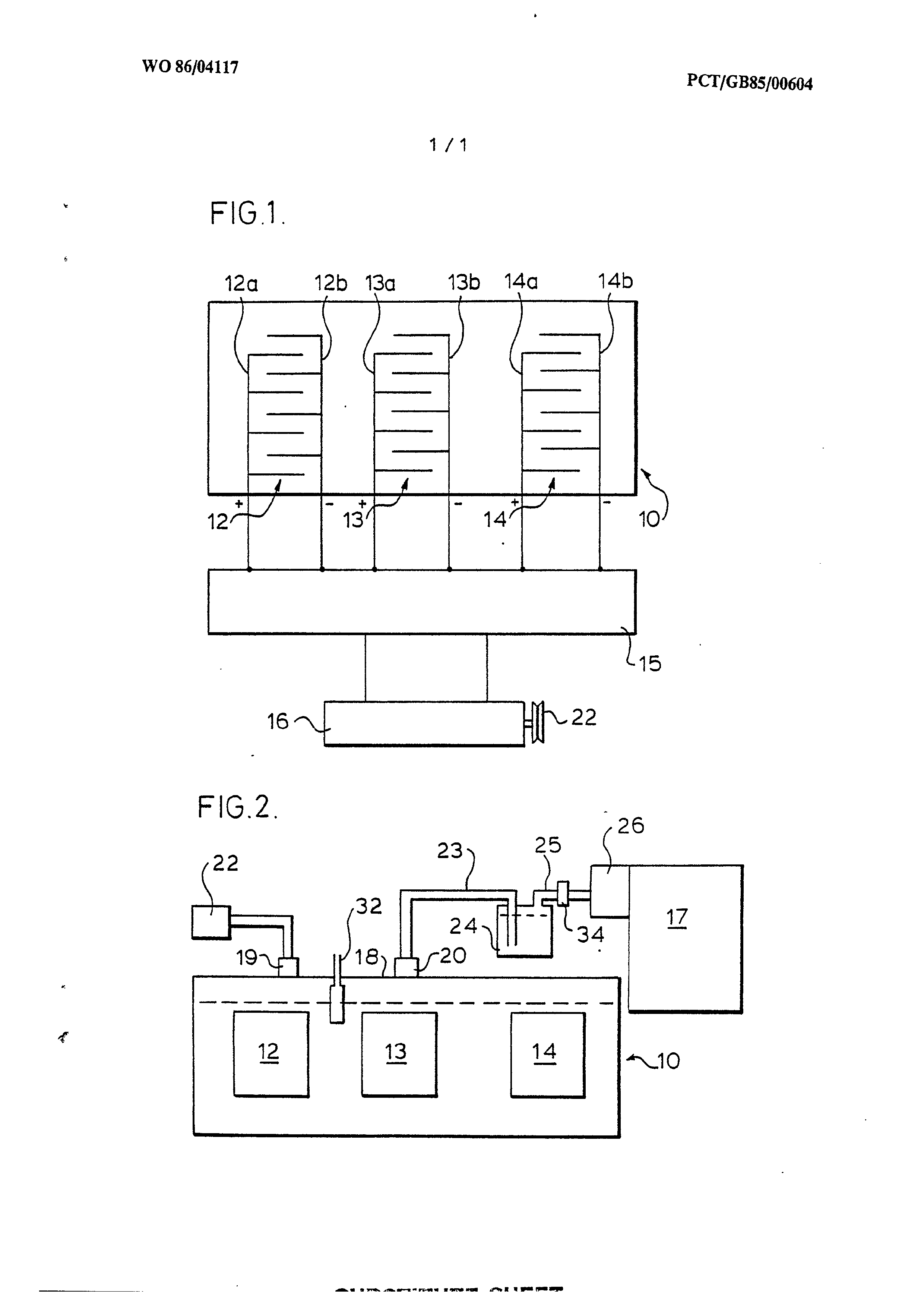
Fig.2 is an elevation of the unit of Fig.1 showing diagrammatically the connection of the unit to a fuel system of an internal combustion engine,
Page 12drawing sheetscan →
Page 13scan →
International search report
International Anplication No PCT/GB 85/00604
1, CLASSIFICATION OF SUBJECT PMAATTER (f severa! classiicstion symbols apply. indicate all) §
According to international Patent Classification {1PC) or to both National Classification and IPC li. FIELOS SEARCHED
Minimum Documentation Searched 7
Classification System | Classification Symbals
Documentation Searched other than Minimum Oocumentation to the Extent that such Documents are Inciuded In the Fields Searched ®
Il, OOCUMENTS CONSIDERED TO BE RELEVANT*
Category * | Citation of Document, '' with Indication, where appropriate, of the relevant passages 12 Relevant to Claim No. 3 column 3, lines 56-68; column 4, lines 17,18
X | FR, A, 1016236 (DEVERREWAERE) 5 November see page 1, left-hand column, lines 1,2,5,8,9,18 1-17, right-hand column, lines 5-13
* Special categories of cited documents: 10
"A" document defining the genera! state of the art which Is not considered to be of particular relevance
“&" earher documant but published on or after the international filing date
“L" document which may throw doubts on priority claim(s) or which 18 cited to establish the publication date of another Citation or other special reason (as specified)
“O" document referring to an oral disclosure, usa, exhibition or other means
“P" document gudlished prior to the international filing date but later than the priority date claimed
“T" Sater document published after the international filing date or oriority date and nat in conflict with the application but cited to understand the principle or theory underlying the invention document of particular relevance; the claimed invention cannot be considered novel or cannot de considered to involve an inventive step document of particular ralevance; the claimed invention cannot be considered to involve an inventive step when the document is combined with one or more other such documents, such combination being obvious to a person skilled in the art.
document mambar of the same patent family
Iv. certification
Date of the Actual Completion of tne International Search
5th March 1986
Date of Malling of this International Search Report
International Searching Authority
Signature of Authorized cer
SOWA as
Form PCT/ISA/210 (second sheet) (January 1985)
Page 14scan →
International Application No. PCT/GB 85 / 00604 - 2-
Ii. DOCUMENTS CONSIDERED TO BE RELEVANT (CONTINUED FROM THE SECOND SHEET)
Catagory * | Citation of Document, with indication, where appropriate, of the relevant passages | Relevant to Claim No see abstract, the first 4 lines; 1,2,3,5,8,9% column 6, lines 3-8
Form PCT:ASA:210 (extra sheet) (January 1985)
Page 15scan →
Annex to the international search report on
International application no. pct/gb 85/00604 (sa 11730)
This Annex lists the patent family members relating to the patent documents cited in the above-mentioned international search report. The members are as contained in the European Patent Office EDP file on 12/03/86
The European Patent Office is in no way liable for these particulars which are merely given for the purpose of information.
Patent document Publication Patent family Publication cited in search date member(s) date report
A aE ee A et mh Se et nme oe ne oe ce ok se oan se ee ee ee ee
For more details about this annex:
see Official Journal of the European Patent Office, No. 12/82
Provenance
- Collection
- Patents citing this work
- Pages
- 15
- Method
- pdftoppm 300dpi + tesseract 5 (eng)
- Patent office record
- patents.google.com →
- Source
- Google Patents citing-documents table
- Assignee
- Iorwerth Thomas
- Published
- 1986-07-17
- Transcribed from
- patentimages.storage.googleapis.com →