(30)
Pipe
Also written loop pipe · tubing · FILED
Where it is first named
(ll) (A) No 1213 671 (45) ISSUED 861104 (52) CLASS 353-14 C.R. CL. 355-1 (51) INT, CL. HOLF 31/00,27/24as) ca) CANADIAN PATENT «2 (54) Electrical Particle Generator (72) Meyer, Stanley A., U.S.A. (21) APPLICATION No. (22) FILED (30) PRIORITY DATE
How it is written
- (pipe 30) 3×
- (tubing 30) 3×
- (loop pipe 30) 2×
- (30) 1×
Drawings 2
-
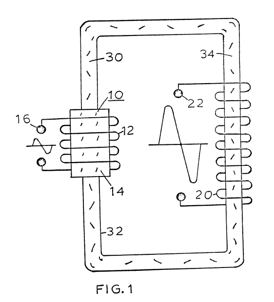
With particular reference to Figures 1 and 2 there is illustrated the invention in its mostly simplified schematic embodiment. · Electrical Particle Generator
-
Figure 6 illustrates a concentric spiral configuration of the tubing 50 having the secondary windings 53 wound over it's entirety. · Electrical Particle Generator
Where it is named · 9
Electrical Particle Generator 9×
-
loop pipe (loop pipe 30)
The magnetic accelerator assembly comprises primary windings 12 a magnetic core 14 and voltage taps 16. The primary windings are positioned around end 32 of closed loop pipe 30 or tubing of non-magnetic material.
-
loop pipe (loop pipe 30)
At the opposite end 34 of the closed loop pipe 30 there is positioned thereon secondary windings 20. A voltage tap 22.on secondary winding 20 permits the utilization of the voltage induced therein.
-
pipe (pipe 30)
Within the pipe 30 there is encapsulated a substantial quantity of magnetic elements 40 of Figure 2. …
-
tubing (tubing 30)
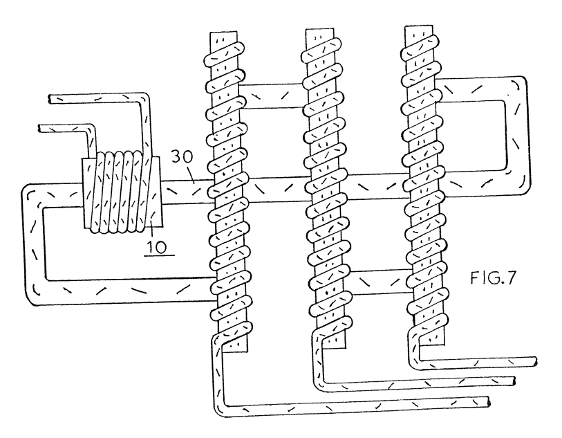
In Figure 7 the particle accelerator 10 is wound over the tubing 30 much in the same manner as the Figures 1 and 2. However, in this embodiment the tubing 30 is a continuous closed loop but ina series, parallel configuration. That is electrically there are three secondary windings with three outputs whereas the tubing 30 is in series through the three secondary windings.
-
tubing (tubing 30)
In Figure 7 the particle accelerator 10 is wound over the tubing 30 much in the same manner as the Figures 1 and 2. However, in this embodiment the tubing 30 is a continuous closed loop but ina series, parallel configuration. That is electrically there are three secondary windings with three outputs whereas the tubing 30 is in series through the three secondary windings.
-
tubing (tubing 30)
In Figure 7 the particle accelerator 10 is wound over the tubing 30 much in the same manner as the Figures 1 and 2. However, in this embodiment the tubing 30 is a continuous closed loop but ina series, parallel configuration. That is electrically there are three secondary windings with three outputs whereas the tubing 30 is in series through the three secondary windings.
-
pipe (pipe 30)
Again, the pipe 30 is described as a non-magnetic pipe. There are certain non-magnetic pipes that would not be operable in the present invention. That is, the pipe 30 must be capable of passing magnetic lines of force; and that it is these magnetic lines of force that traverse the inductive field of the secondary windings 20 to induce a voltage/current therein.
-
pipe (pipe 30)
Again, the pipe 30 is described as a non-magnetic pipe. There are certain non-magnetic pipes that would not be operable in the present invention. That is, the pipe 30 must be capable of passing magnetic lines of force; and that it is these magnetic lines of force that traverse the inductive field of the secondary windings 20 to induce a voltage/current therein.