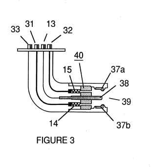
Figure (3)
Figure (3)
How it is written
- (3) 1×
Drawings 1
-
Figure 3A is a frontal view of the operative end of the injector. · Water Fuel Injection System
Where it is named · 1
Water Fuel Injection System 1×
-
A flange mounted injector is shown in cross-Section in Figure 3 which shows the fuel mixture inlets and illustrates an alternative three (3) nozzle configuration leading to the polarization (voltage) and combustion zones in which one nozzle 3la, 32a and 33a for each of the three gas mixtures is provided, connected to supply lines 31 and 32 (33 not . …