Figure (4)
Figure (4)
How it is written
- (4) 2×
Drawings 2
-
Captioned as this figure · Water Fuel Injection System
-
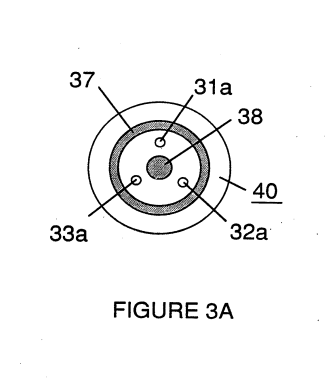
Figure 3A is a frontal view of the operative end of the injector. · Water Fuel Injection System
On this figure 1
Where it is named · 2
Water Fuel Injection System 2×
-
Multiple injectors may be arranged in a gang as shown in Figure 4 in which injectors 40, 41, 42, 43, 44, 45, 46, 47, 48 and 49 are arranged concentrically in an assembly 50. Such a ganged array is useful in applications having intensive energy requirements such as jet aircraft engines, and blast furnaces.