(30)
Gas Accumulator Cavity
Also written dual gas accumulator cavity · accumulator cavity · Accumulator cavities
Where it is first named
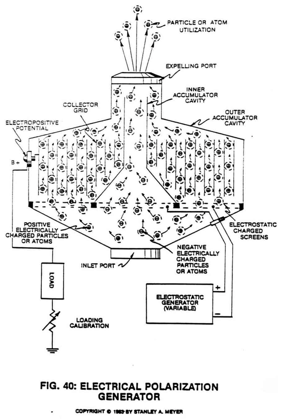
Circuit State: Moving electrically charged atoms (1/2) through an electrical grid system (50) inserted into a dual gas accumulator cavity (30/40) separated by an ambient air filtering screen assembly (20A) of opposite voltage polarity… forming Electrical Polarization Generator (90), as illustrated in Figure 40 as to Figure 8 subtitled “Regenerative Energy Feedback Module.”
How it is written
- (30) 3×
- (30/40) 2× with (40) Dual Gas Accumulator Cavity
Drawings 1
-
The figure it sits on · ELECTRICAL POLARIZATION GENERATOR
Where it is named · 5
ELECTRICAL POLARIZATION GENERATOR 5×
-
dual gas accumulator cavity (30/40)
Circuit State: Moving electrically charged atoms (1/2) through an electrical grid system (50) inserted into a dual gas accumulator cavity (30/40) separated by an ambient air filtering screen assembly (20A) of opposite voltage polarity… forming Electrical Polarization Generator (90), as illustrated in Figure 40 as to Figure 8 subtitled “Regenerative Energy Feedback Module.”
-
accumulator cavity (30)
The attracted and moving positive charge gas ions (1) now pass through and beyond screen-port (4) into accumulator cavity (30);
-
Accumulator cavities (30/40)
Accumulator cavities (30/40) are electrically isolated from one another to prevent electrical discharging of said gas ions during application use.
-
gas accumulator cavity (30)
To maintain a constant flow of electrons toward said electrical terminal (8), simply maintain the gas-flow through the gas accumulator cavity (30).
-
gas accumulator cavity (30)
The negative charged gas ions (2a xxx 2n) passing through gas accumulator (40) is simply discharged through gas exit port (12) while gas ions (1a xxx 1n) passing through gas accumulator cavity (30) are discharged through a separate exit port (13).