Figure (1)
Figure (1)
How it is written
- (1) 9×
Drawings 1
-
Page 26 · Hydrogen Aeration Injection System
Where it is named · 9
Hydrogen Aeration Injection System 9×
-
19 itembodiment of Figure 1.
-
21 i;shown in Figure 1,
-
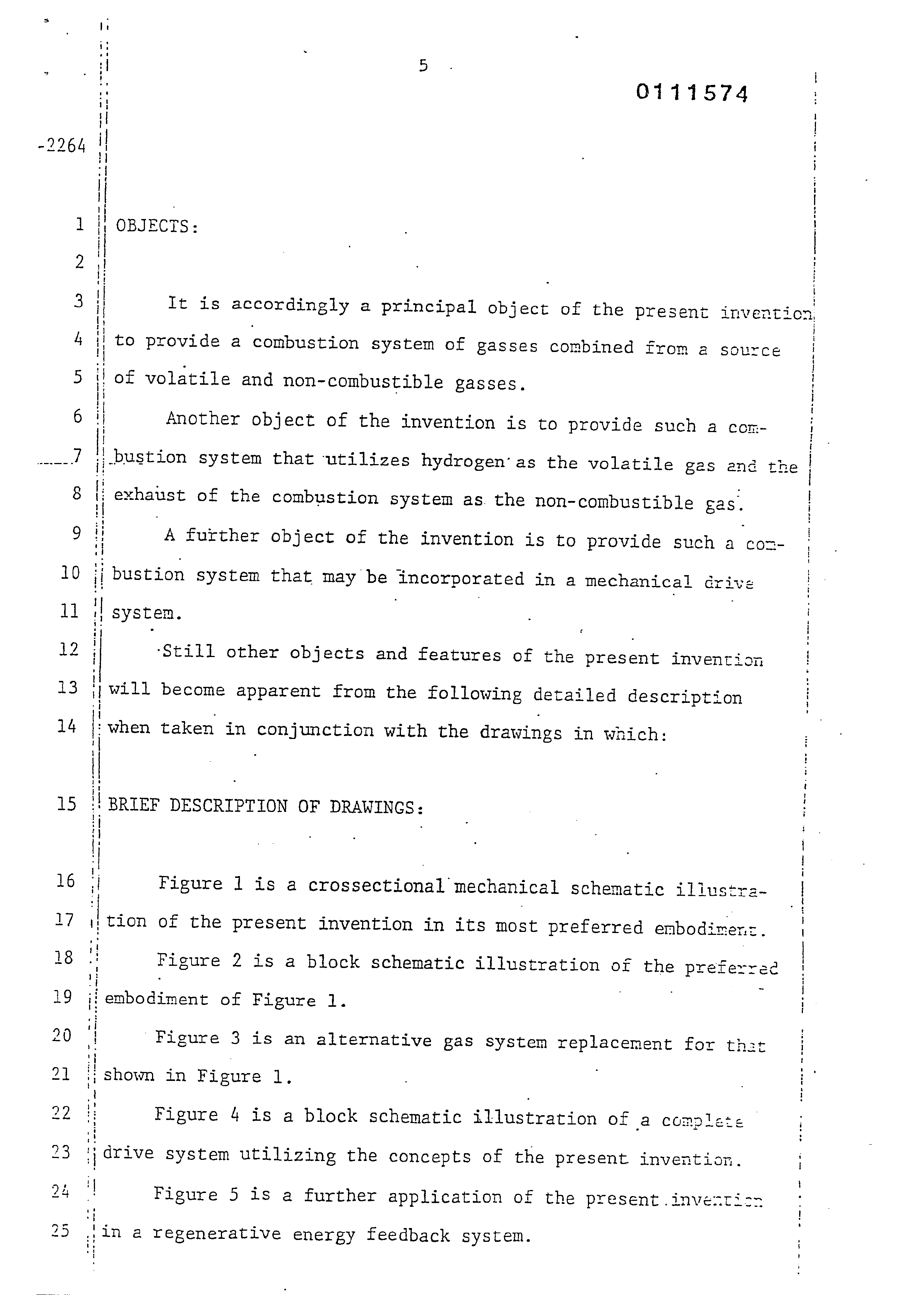
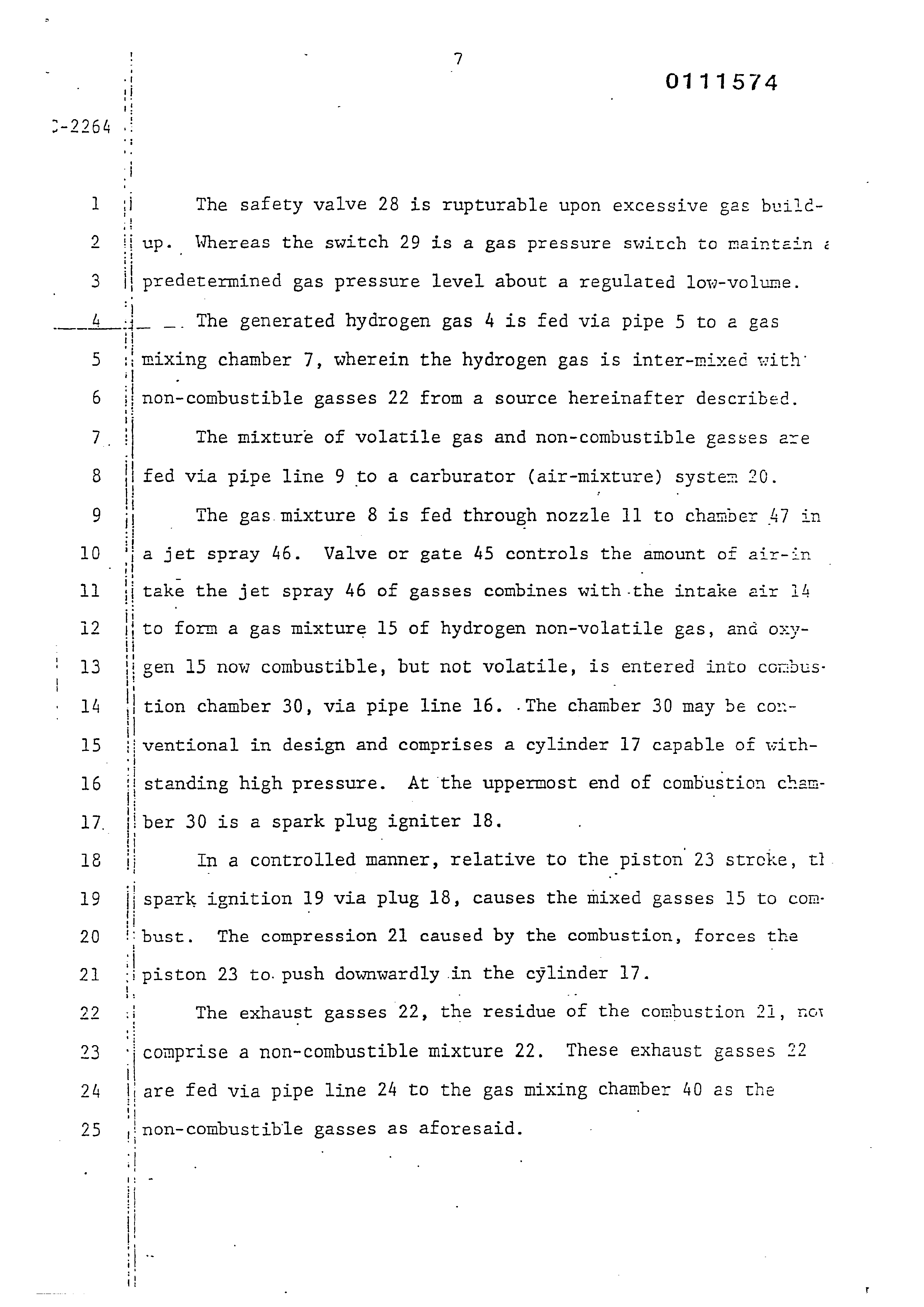
“Referring particularly to Figure 1 the complete overall conbustion system is illustrated together with a mechanically driven piston. Similarly, Figure 2 illustrates the complete system in ; its preferred embodiment.
-
With particular reference to Figure 1, the hycrogen source
-
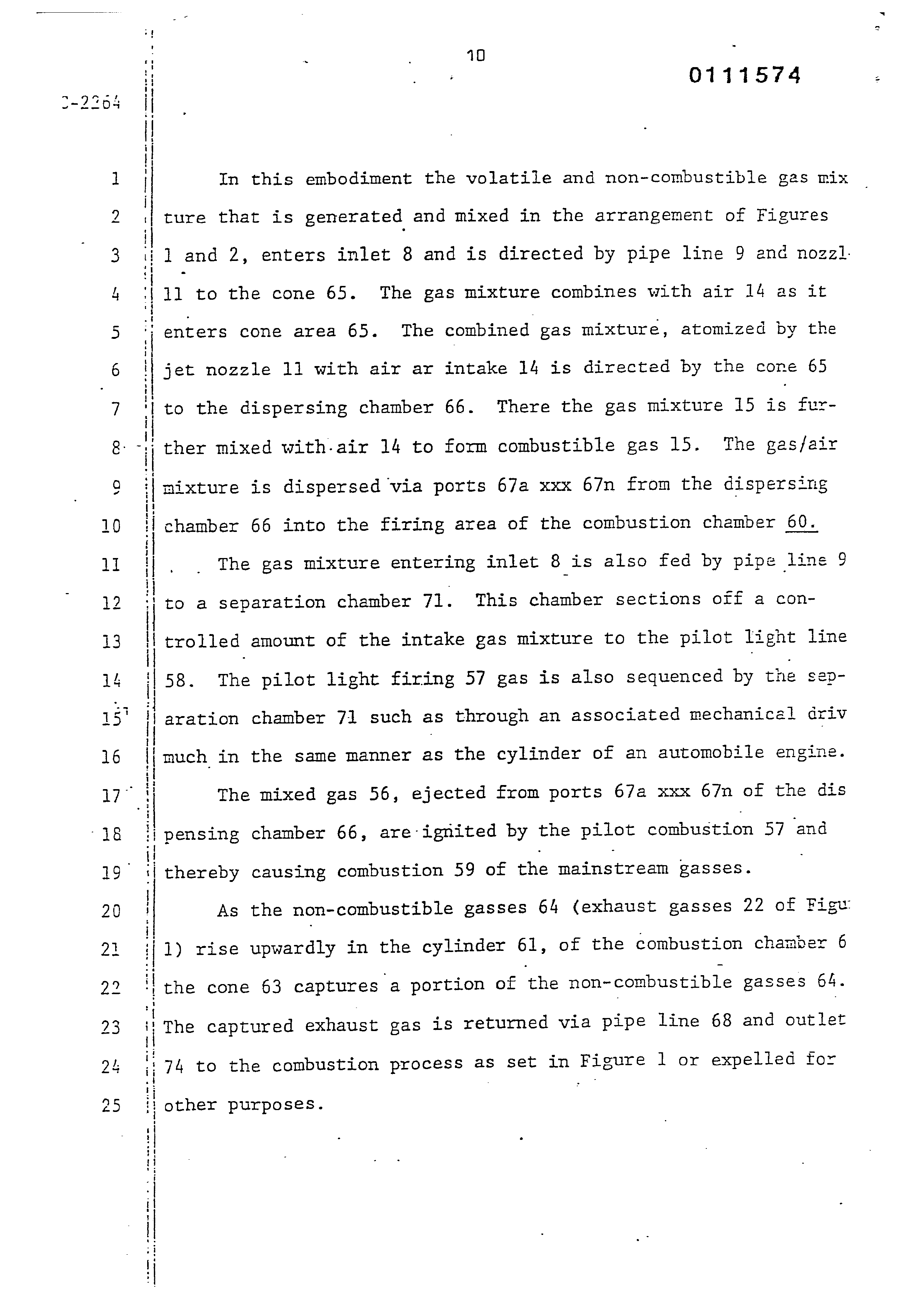
Figure 1. In this embodiment the components are depicted more
-
74 to the combustion process as set in Figure 1 or expelled for
-
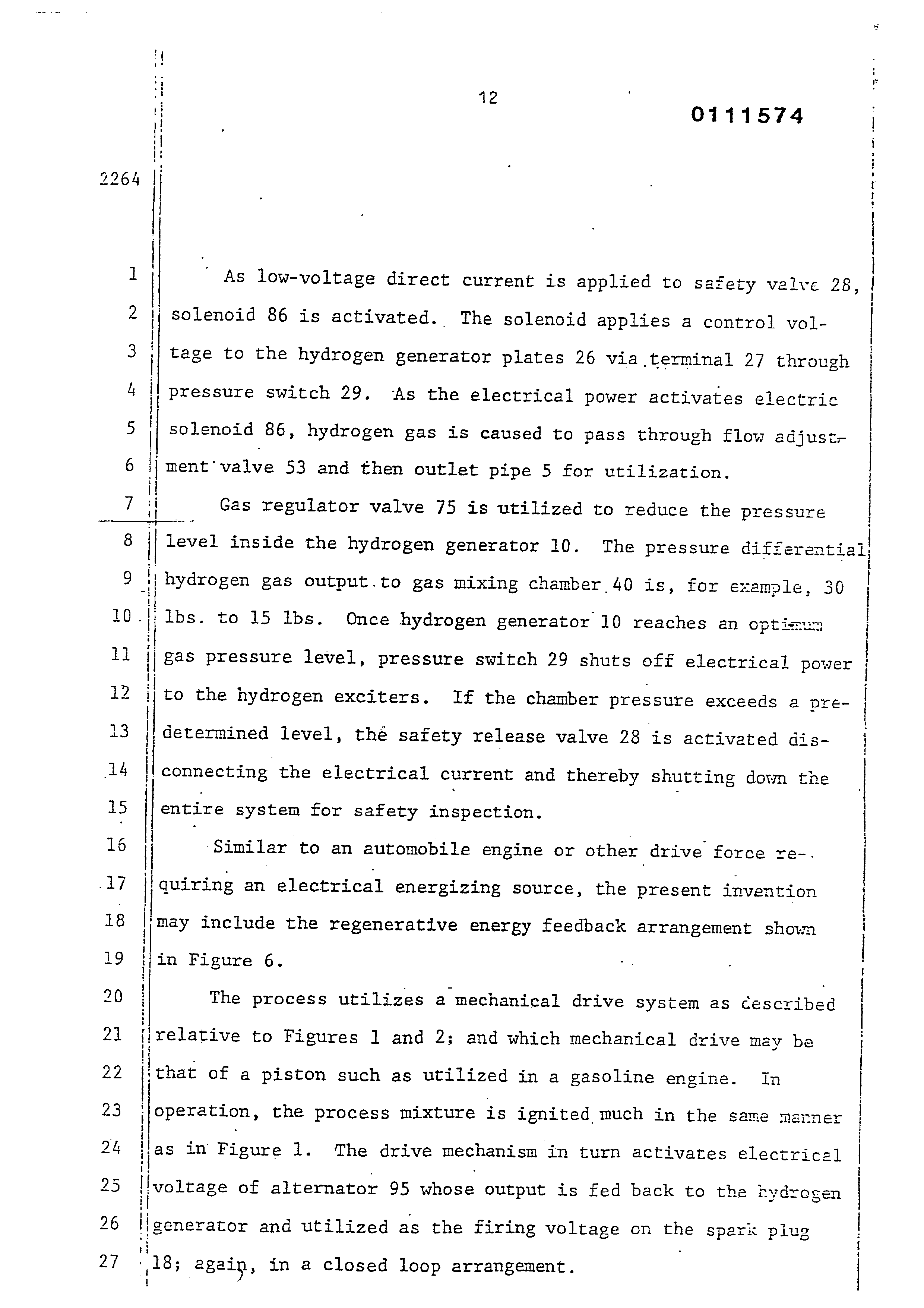
as in Figure 1. The drive mechanism in turn activates electrical
-
significantly, applicable to the process of the hydrogen generator That is, again referring to Figure 1, the electrical voltage app=
-
* Column 3, lines 19-64; figure 1