Figure (1)
Figure (1)
How it is written
- (1) 4×
Drawings 1
-
1. A combustion system for mechanical drive systems using gaseous hydrogen as fuel, com- · Hydrogen Aeration Injection System
On this figure 11
- 10 Hydrogen Generator
- 11 Jet Nozzle
- 14 Air
- 60 Combustion Chamber
- 61 Cylinder
- 63 Cone
- 64 Exhaust Gases
- 65 Konus
- 69 Outlet Exhaust
- 73 Opening
- 74 Outlet
Where it is named · 4
Hydrogen Aeration Injection System 4×
-
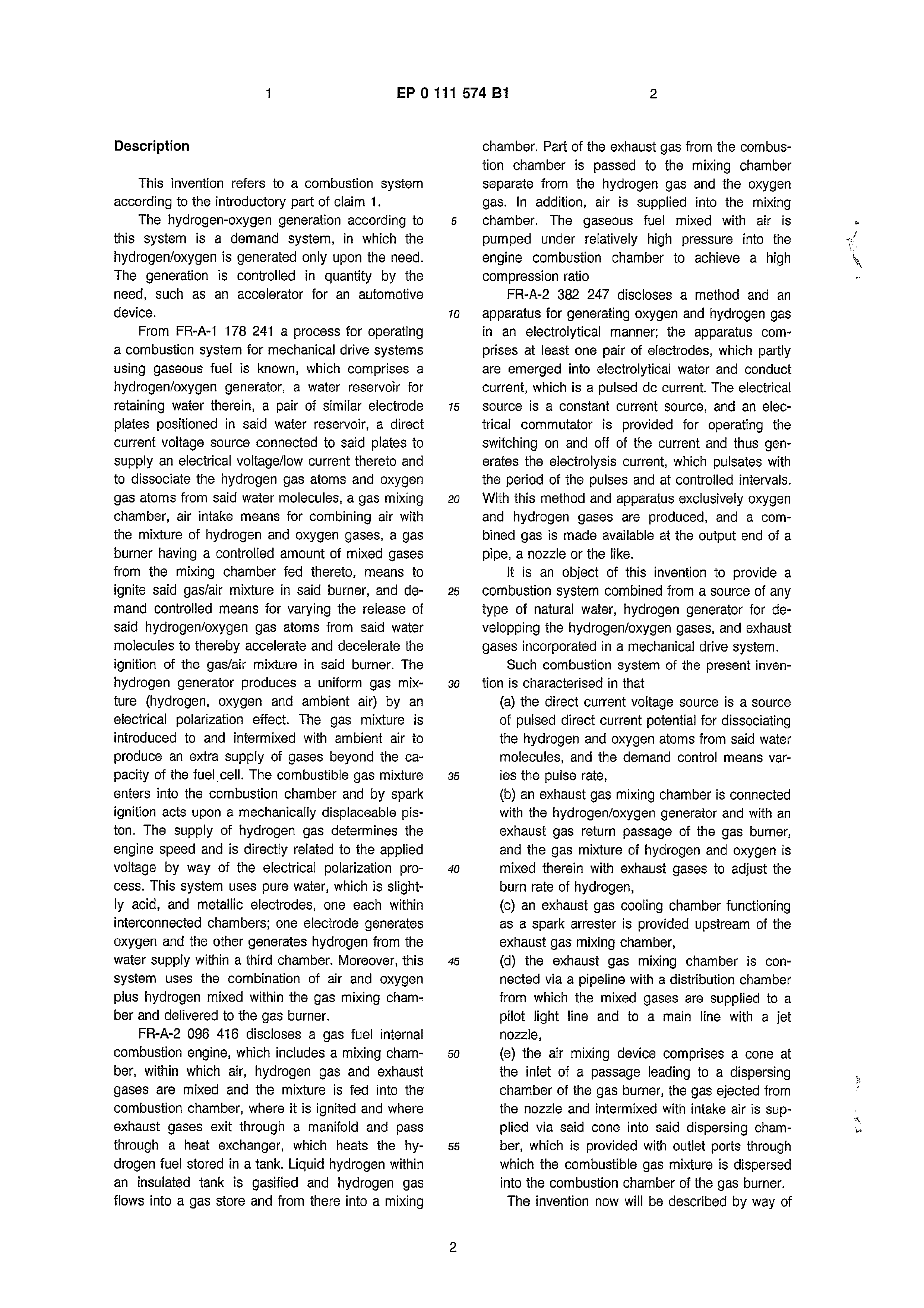
Figure 1 is a schematic illustration of a part of the present invention showing the hydrogen/oxygen generator, and
-
Figure 1 shows the hydrogen source 10 which is a hydrogen/oxygen generator. …
-
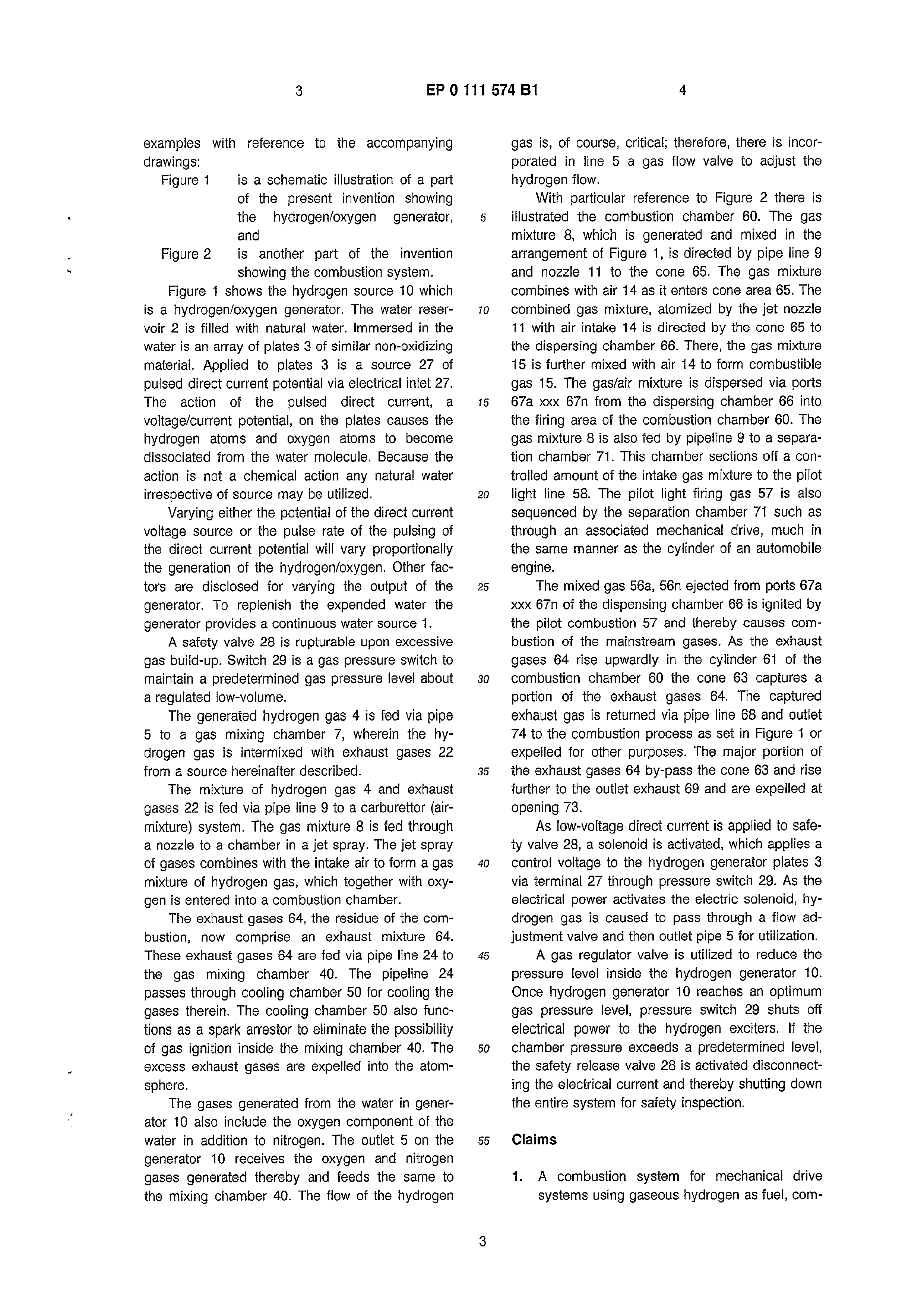
With particular reference to Figure 2 there is illustrated the combustion chamber 60. The gas mixture 8, which is generated and mixed in the arrangement of Figure 1, is directed by pipe line 9 and nozzle 11 to the cone 65. …
-
… The captured exhaust gas is returned via pipe line 68 and outlet 74 to the combustion process as set in Figure 1 or expelled for other purposes. The major portion of the exhaust gases 64 by-pass the cone 63 and rise further to the outlet exhaust 69 and are expelled at opening 73. :