(EE)
variable gate Circuit
Where it is first named
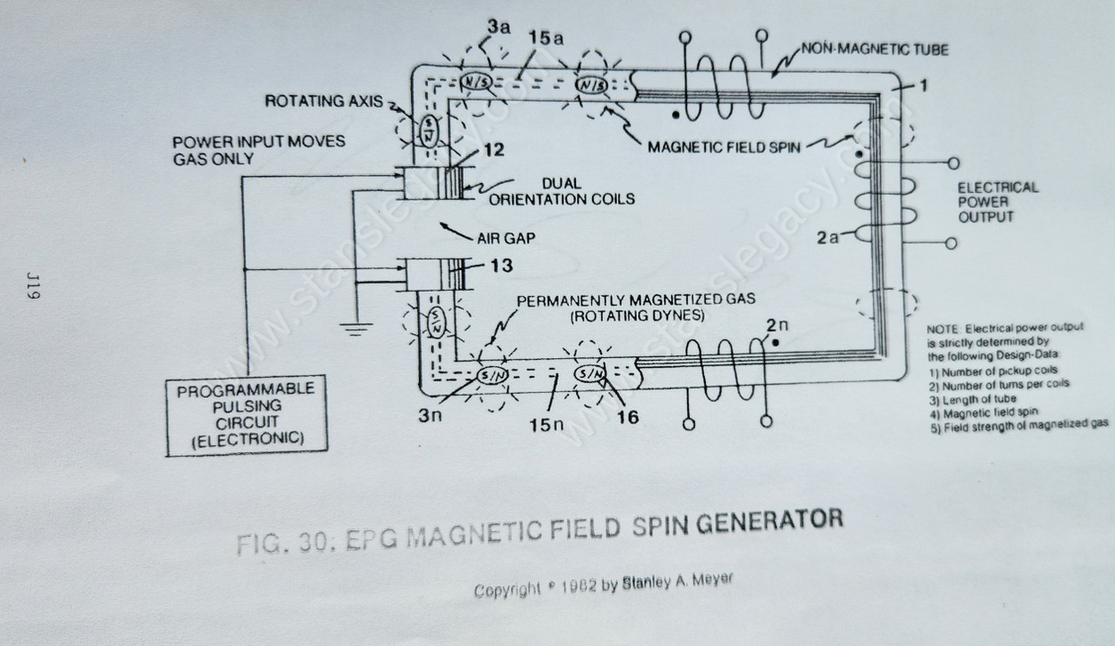
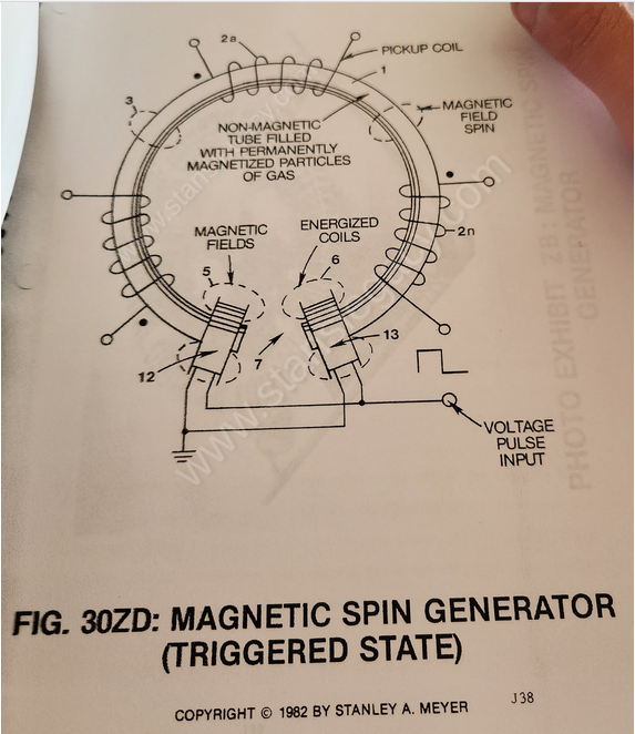
As shown in Figure 9XB as to Figure 9XAA, variable gate Circuit (EE) is electrically connected to both orientation coils (12/13), as shown in Figure 30 as to Figure 30ZC and Figure 30ZD.
How it is written
- (EE) 2×
Drawings 1
-
allowing said electromagnetic field (3) to expand, to pass through and beyond pickup coils (2a xxx 2n), as illustrated in Figure 30ZD. · MAGNETIC SPIN GENERATOR
Where it is named · 2
MAGNETIC SPIN GENERATOR 2×
-
variable gate circuit (EE)
By simply "switching on" said variable gate circuit (EE), a voltage pulse of a given duration is applied to both orientation coils simultaneously... producing electromagnetic fields (5/6) of equal magnitude in a North to South relationship to said air gap (7) as shown in Figure 30ZD.