Figure (2)
Figure (2)
How it is written
- (2) 6×
Drawings 1
-
Page 6 · Solar Heating System
On this figure 4
Where it is named · 6
Solar Heating System 6×
-
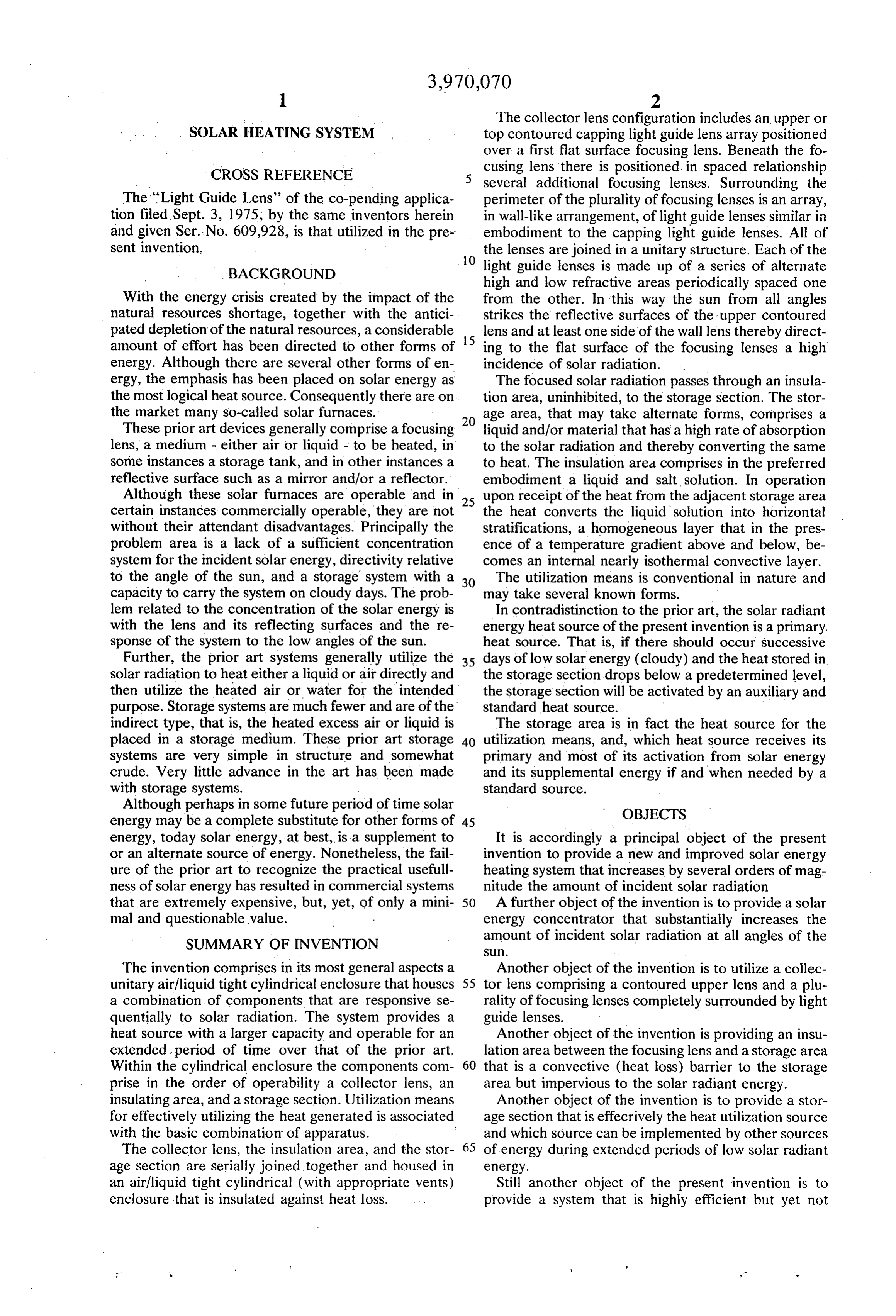
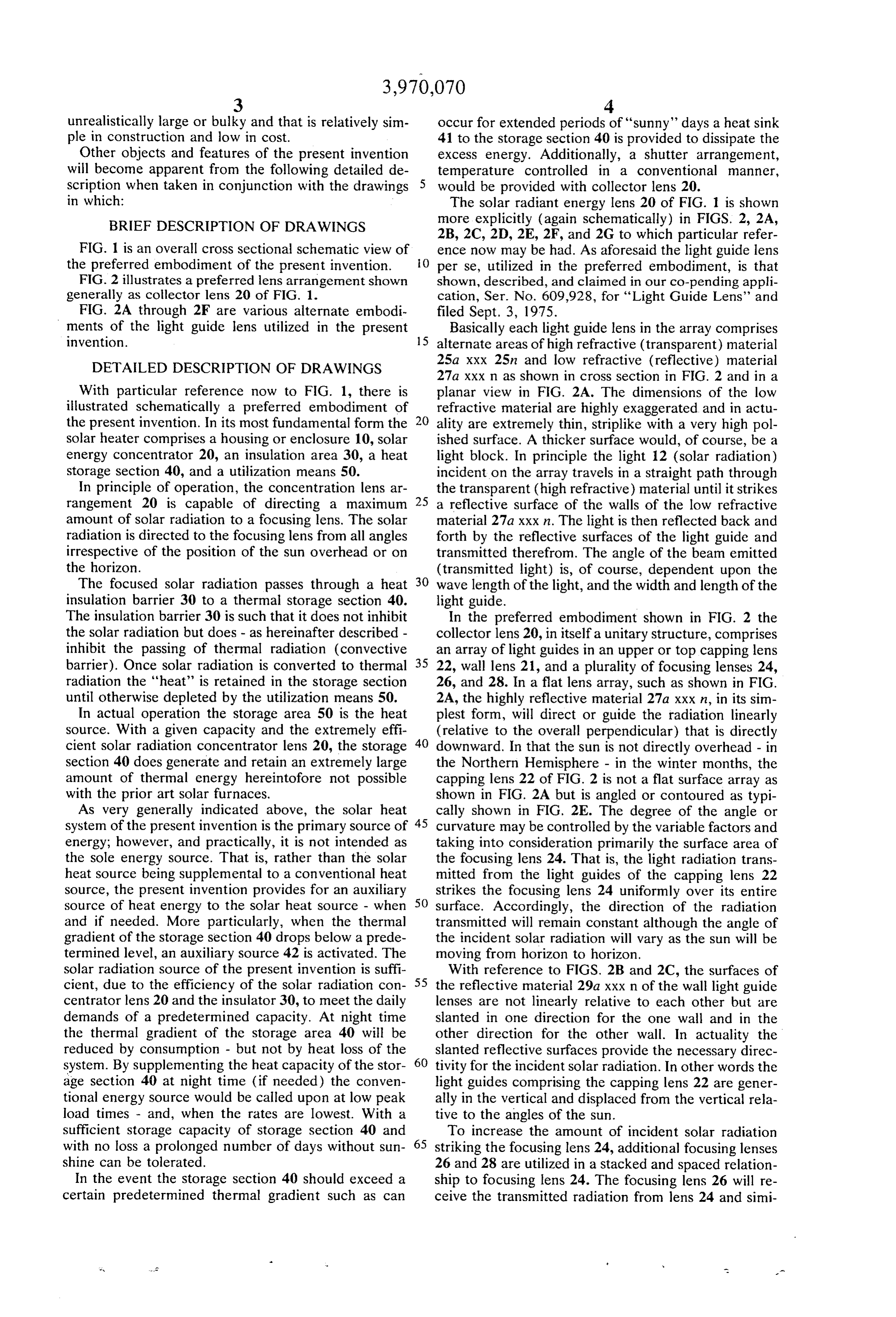
… ally each light guide lens in the array comprises alternate areas of high refractive (transparent) material 25a xxx 25n and low refractive (reflective) material 27a xxx n as shown in cross section in FIG. 2 and in a planar view in FIG. …
-
In the preferred embodiment shown in FIG. 2 the collector lens 20, in itself a unitary structure, comprises an array of light guides in an upper or top capping lens 22, wall lens 21, and a plurality of focusing lenses 24, 26, and 28. …
-
… In that the sun is not directly overhead - in the Northern Hemisphere - in the winter months, the capping lens 22 of FIG. 2 is not a flat surface array as shown in FIG. …
-
The structure of the overall system of FIG. 1 and particularly the collector lens 20 of FIG. 2 comprising top lens 22 and wall lens 21 can take most any overall configuration - round, square, cylindrical, and so on. …
-
Referring again to the overall preferred embodiment of FIG. 1 and particularly to the lens schematic of FIG. 2, the focusing lenses 24, 26, and 28 may now be described. …