Figure (2)
Figure (2)
How it is written
- (2) 11×
Drawings 3
-
LASER , ACCELERATOR - VOLTAGE INTENSIFIER 7 COMPENSATING (VIC) CIRCUIT SENSORS | ENGINE Le TEMPERATURE | BAROMETRIC PRESSURE ~ GAS PRESSURE 9 FIGURE 2 · Hydrogen Gas Fuel And Management System For An Internal Combustion Engine Utilizing Hydrogen Gas Fuel
-
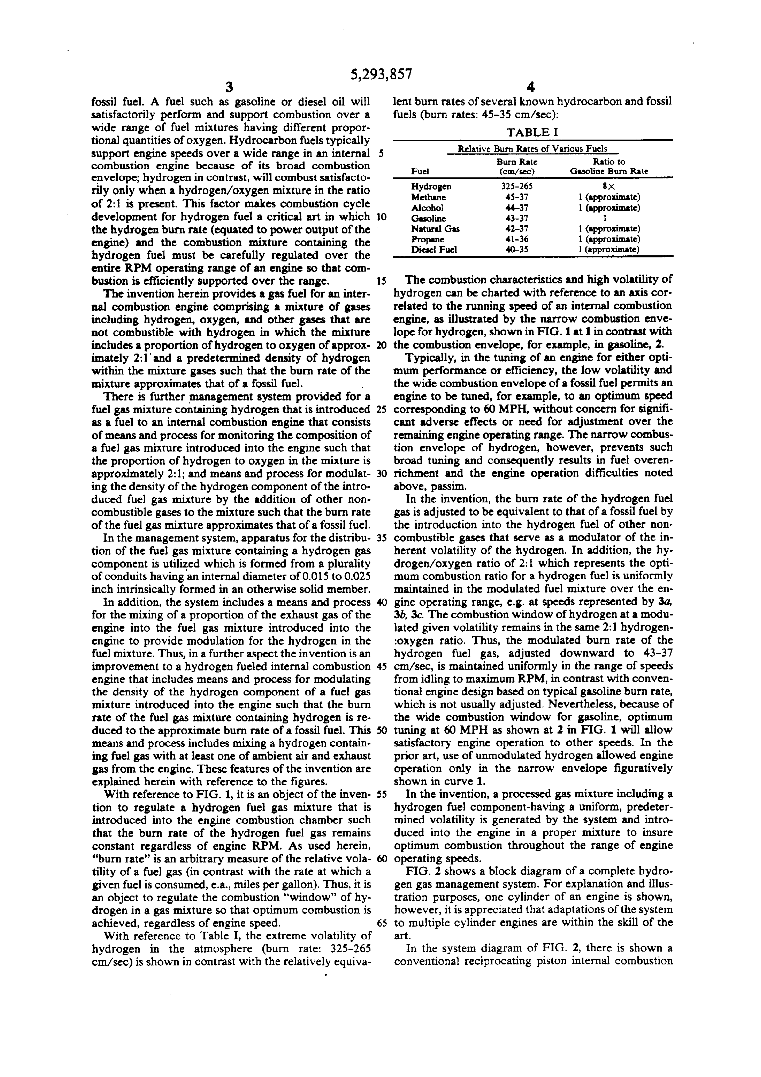
In the system diagram of FIG. 2, there is shown a conventional reciprocating piston internal combustion · Hydrogen Gas Fuel And Management System For An Internal Combustion Engine Utilizing Hydrogen Gas Fuel
On this figure 4
Where it is named · 11
Hydrogen Gas Fuel And Management System For An Internal Combustion Engine Utilizing Hydrogen Gas Fuel 11×
-
LASER , ACCELERATOR - VOLTAGE INTENSIFIER 7 COMPENSATING (VIC) CIRCUIT SENSORS | ENGINE Le TEMPERATURE | BAROMETRIC PRESSURE ~ GAS PRESSURE 9 FIGURE 2
-
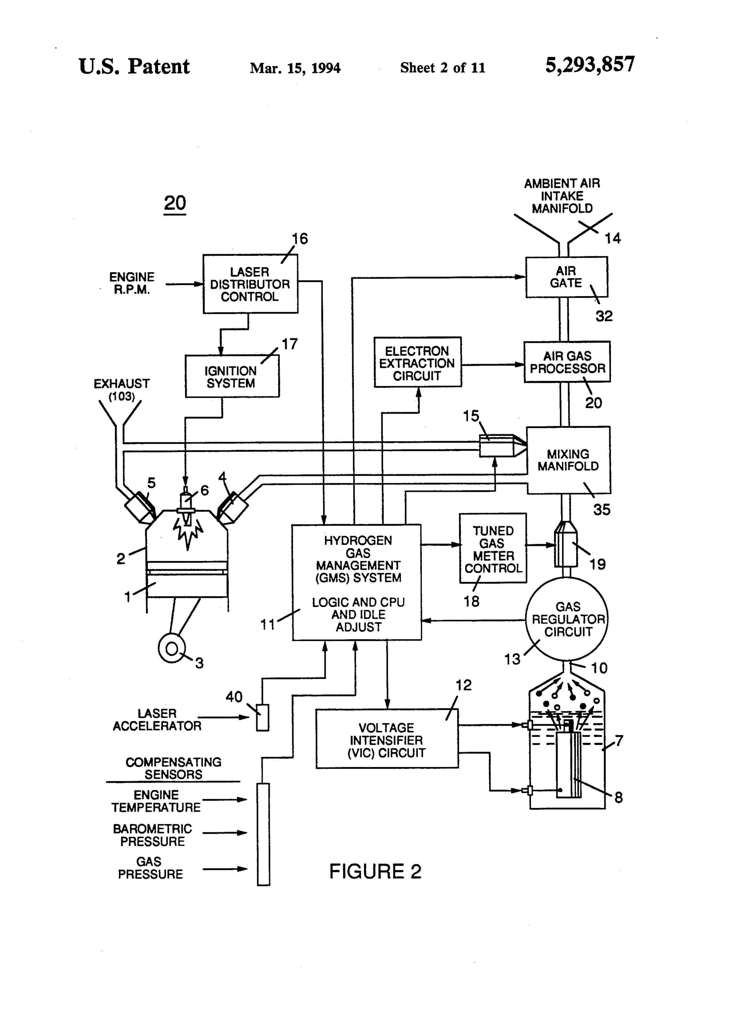
FIG. 2 is a block diagram of a combustion management system for a hydrogen containing fuel gas mixture that is injected into a combustion chamber, showing the interrelationship of system management controls with various engine parameters.
-
FIG. 2 shows a block diagram of a complete hydrogen gas management system. For explanation and illustration purposes, one cylinder of an engine is shown, however, it is appreciated that adaptations of the system to multiple cylinder engines are within the skill of the art.
-
In the system diagram of FIG. 2, there is shown a conventional reciprocating piston internal combustion
-
FIG. 3 illustrates an appropriate mechanical configuration adapted to the overall system shown in FIG. 2. …
-
In a preferred mode, air gas processor shown at 20 in FIG. 2 and in greater detail in FIGS. …
-
conversion must be correspondingly increased. As noted above in the preferred embodiment of FIG. 2, the pulse generating circuit of the method is interconnected with the management module such that fuel gas is generated by the fuel cell gas generator on demand and such that the fuel cell operation is also responsive to sensed parameters and control signals generated. …
-
FIG. 4, 4A and 4B show a side frontal cross-section and plan view from the top and bottom of a type of air gas processor such as 20 shown in FIG. 2. …
-
… Thus, inert water vapor exhaust gas, (e.g., from valve § in FIG. 2), as well as ambient air, is used as a dilutent. …
-
… Too much of an oxygen excess may result in the production of undesirable NOx exhaust gases; however, this is not a significant problem and may be resolved in the engine system of FIG. 2 by the introduction of more exhaust gas rather than air as a dilutent. …
-
Sensors of the system of FIG. 2 monitor air pressure and temperature which affect the dilution of the hydrogen fuel. …