Figure (10)
Figure (10)
How it is written
- (10) 8×
- (Figure 10) 1×
Drawings 1
On this figure 1
Where it is named · 9
A control and driver circuits for a hydrogen gas fuel producing cell 9×
-
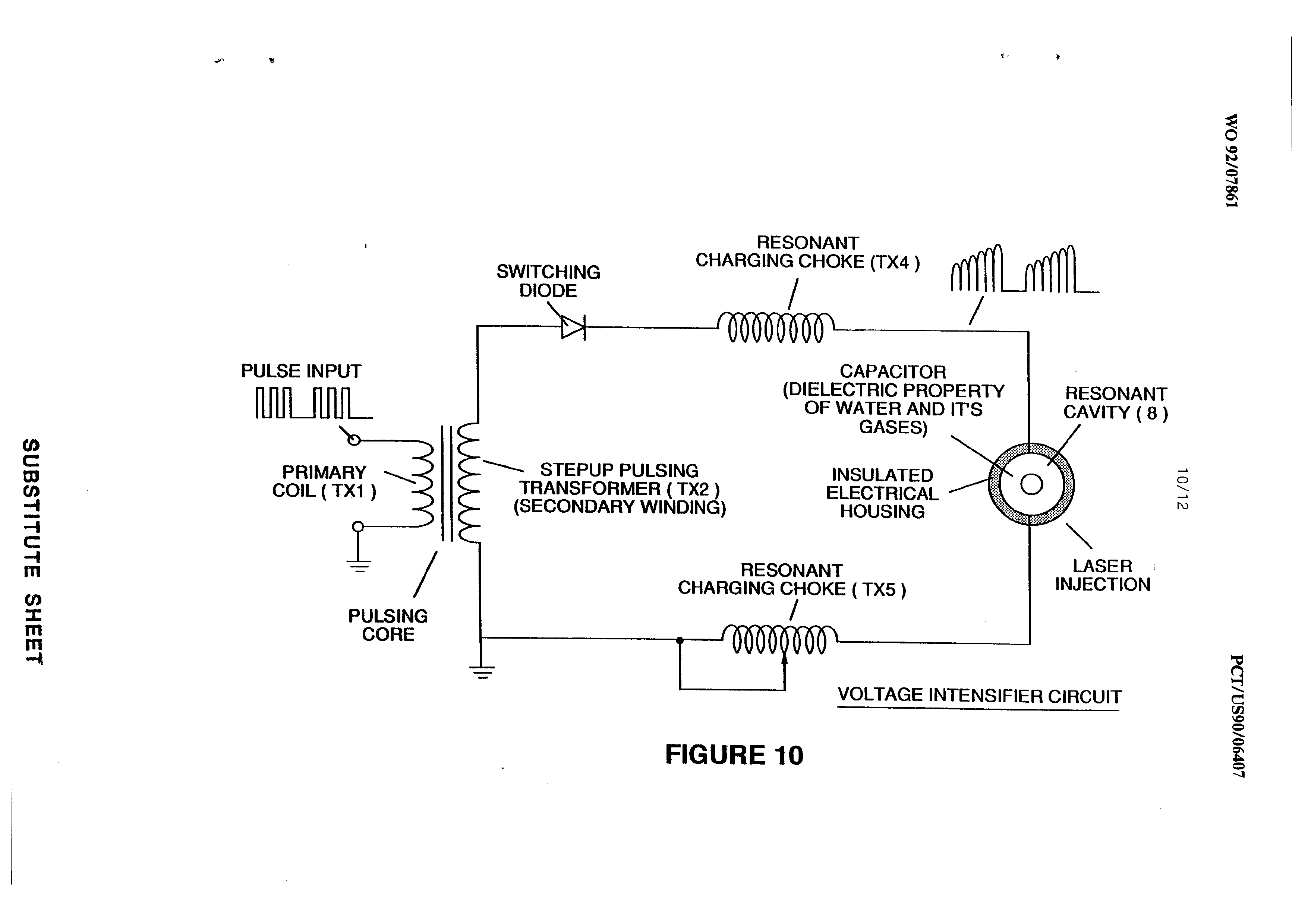
Figure 10 shows the pulsing core and the voltage intensifier circuit that is the interface between
-
intensifier circuit of Figure 10, which, inter alia,
-
The high speed switching diode shown in Figure 10 prevents charge leakage from the charged water in the water capacitor cavity, and the water capacitor as an overall capacitor circuit element, i.e., the pulse and Charge status of the water/capacitor never pass through an arbitrary ground. …
-
… The Switching diode in the VIC circuit (Figure 10) performs several functions in the pulsing. …
-
… The Switching diode in the VIC circuit (Figure 10) performs several functions in the pulsing. …
-
The VIC circuit of Figure 10 also includes a ferromagnetic or ceramic ferromagnetic pulsing core capable of producing electromagnetic flux lines in
-
FIGURE 10