
9XA Method
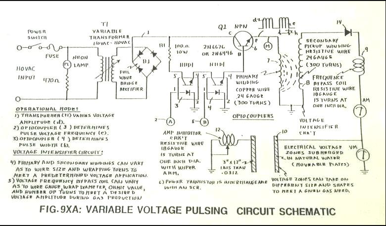
The 9XA was a circuit that Stan used to produce a gated pulse frequency via two H11D1 optocouplers. The optocouplers were driven by two independent stages of 555 timer clock frequency into 3 7490 decade counter ICs. The 7490s provided divisions of 555 frequency, but also produced 50% duty cycle pulses. Below, "A" is one 555/7490 stage and "B" is second 555/7490 stage. The two optocouplers produce an equivalent to AND logic gate.
Figure 1: 9XA schematic
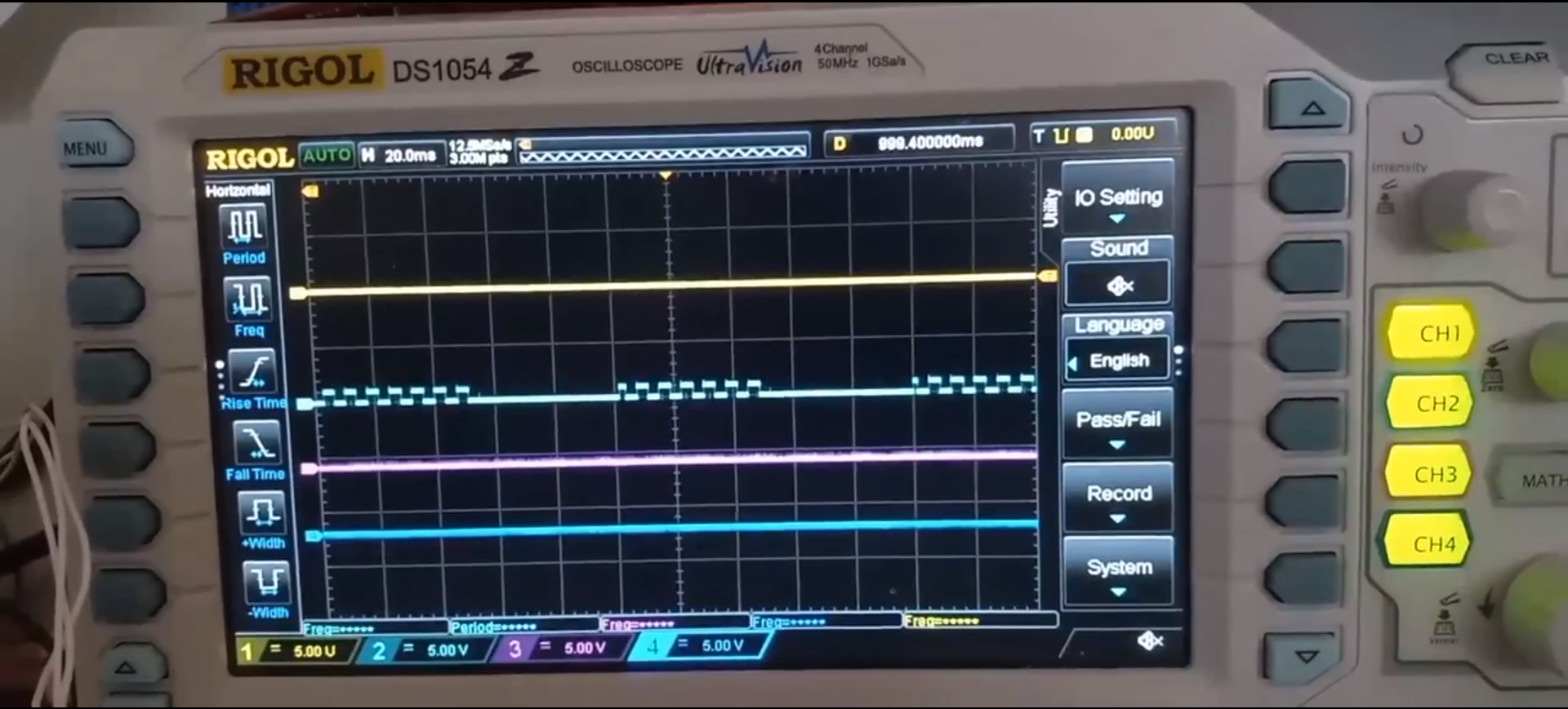
Below is an 9xa scope shot, showing how two independent 9XB style frequency generator's outputs were used to trigger two H11D1 optocouplers to produce a gated pulse train as shown in schematic. In this setup, I had 555's produce a 100khz output to 4 CD4017 dividers. This allowed a 10khz with 50/50 duty cycle to be achieved. LED is just for visual confirmation. If looking closely, you can see how the gating generator isn't synchronized with frequency generator. This causes extra pulses to arise during gated ON times, also called "clock drift".
NOTE: CD4017s were used in place of 7490s, they accomplish the same task with less wiring required.
Video Link: 9XA Circuit Waveform
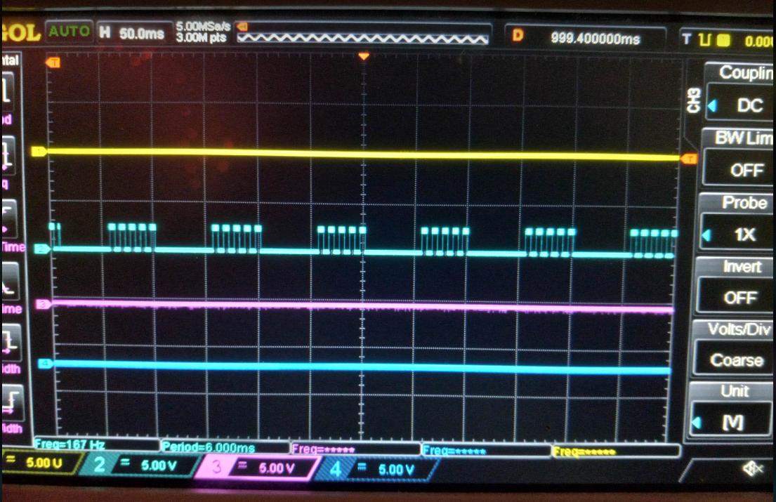
2nd setup had a modification where both signals from 555/CD4017 were fed into an 7408 AND logic gate. This produced the waveform seen below. In this instance, only 1 H11D1 optocoupler was required.
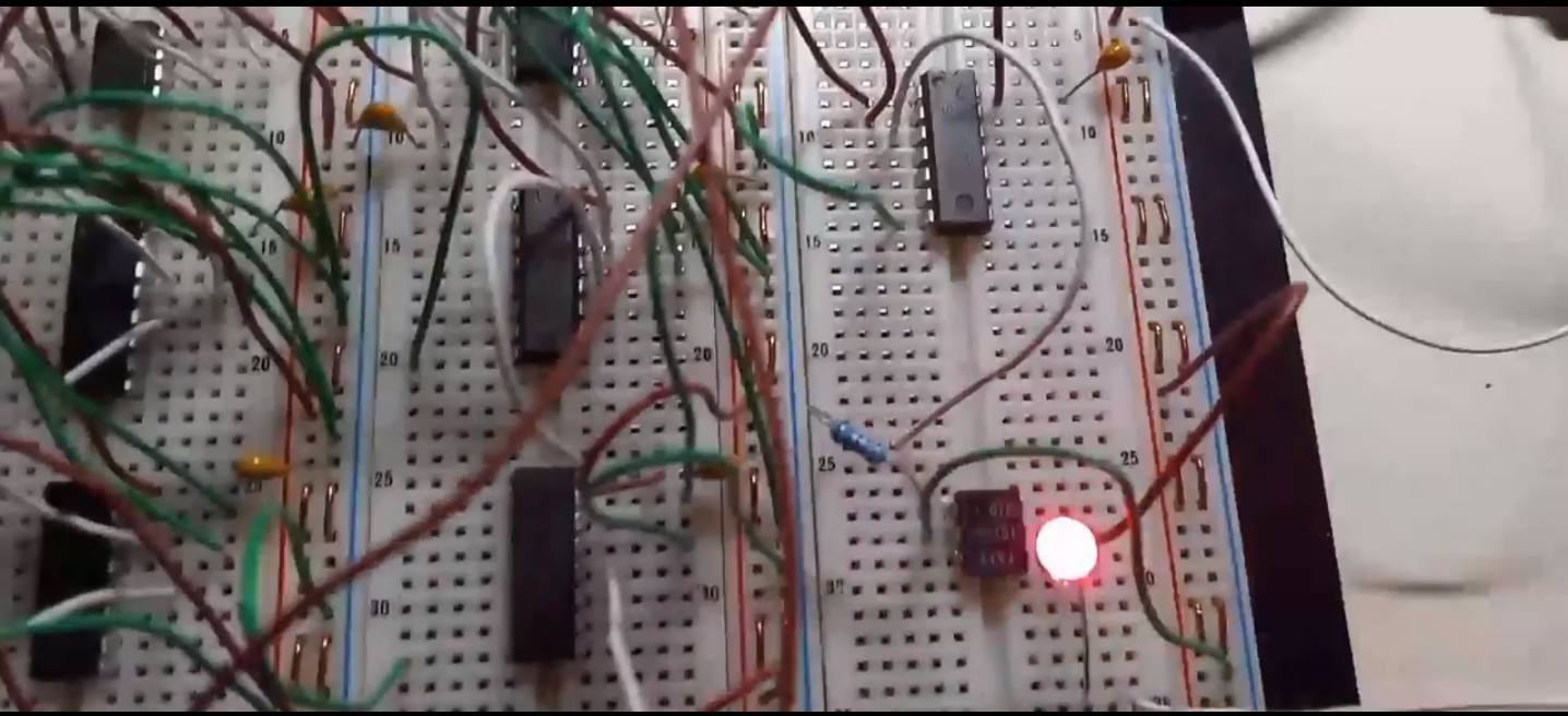
LED providing visual verification of pulse waveform.
Video Link: 9XA, 7408 mod
9XA does provide a 50% duty cycle pulse frequency with a 50% duty cycle gate frequency. However, clock drifting is an issue if both waveform generators are used independently. If both decade counter stages are driven from same 555, a synchronized clock can be achieved. It is unclear if Stan synchronized with one 555.