JP58207610A - Electric Particle Generator
Japan Patent Office (JP)
Patent Application Publication
(Application A)
Patent Application Publication No.:
Showa 58-207610Patent Application Date:
Showa 58 (1983), December 3Application Number:
Showa 58-23664
February 15, 1983Priority Claim:
1982 April 9, USA No. 367051Title of the Invention:
Electric Particle GeneratorApplicant:
Stanley A. Meyer
Grove City, Ohio 43123, USAAgent:
Attorney Nakamura
Title of the Invention
Electric Particle Generator
Scope of Patent Claims
(1) An electric particle generator equipped with a particle accelerator at the end of a tube through which non-conductive magnetic gas flows, and incorporating ionization elements inserted into the unit, which work together with the particle accelerator.
(2) The electric particle generator described in claim 1, where the ionization element operates with low input voltage in the second chamber, and the voltage/electromagnetic field is used to extract and utilize energy from the gas.
(3) The electric particle generator described in claim 1, wherein a second electrode that extracts the ionized particles from the first chamber is installed and operates to capture the energy released.
(4) The ionization element described in claim 1, wherein the element is solid in structure.
(5) The ionization element described in claim 1, wherein the element is a liquid.
(6) The electric particle generator described in claim 1, wherein the particle accelerator is driven by a magnetic coil.
(7) The electric particle generator described in claim 6, wherein the magnetic coil is designed to generate a low input voltage into the first chamber.
(8) The electric particle generator described in claim 7, wherein the low input voltage and the magnitude of electromagnetic force generated by the second coil control the size of the voltage output.
(9) The electric particle generator described in claim 7, wherein the low input voltage is further enhanced by the ionization process.
An electric particle generator in which the first coil’s input voltage is alternating current and operates at a constant frequency, wherein the magnitude of the input voltage/alternating current is low voltage.
An electric particle generator in which the first coil’s input voltage is pulsating direct current and operates at a low voltage.
An electric particle generator in which the first coil’s input voltage is variable, wherein the magnitude of the input voltage/alternating current is modulated to control the output.
An electric particle generator that includes a second chamber where the input voltage is lower than in the first coil and accelerates the ionized particles.
An electric particle generator in which the chamber is separated into three parts.
Each part is connected in series to a brush, and the second coil is connected to each of the brush terminals, with each coil being phased separately. This creates a three-phase alternating current effect.
An electric particle generator where the ionization element is filled with water and has an ionized structure that contributes to enhanced electromagnetic force.
An electric particle generator that is capable of providing particle acceleration by the mechanism of alternating current and low voltage within the chamber.
An electric particle generator in which the first coil and the electromagnetic force created by it send the ionized particles through a tube to a designated location.
Magnetic Field Generator
The magnetic field generator emits magnetic fields to induce particle ionization, passing through a pipe where ionized particles are accelerated. This system magnifies the effect of ionized particles as they pass through the magnetic field system.
3. Detailed Description of the Invention
According to traditional teachings, a magnetic field induces voltage/electric current when passed through, or by passing the magnetic field to a coil or a second system, voltage generation occurs. The basic principle behind this is detailed.
Additionally, in this invention, the first coil element induces voltage/electric current as it moves and reacts to other attached elements. This method of inducing voltage from a moving coil element can result in further acceleration by causing oscillation between the coils.
Thus, the induced voltage from both primary and secondary coils can be magnified. This magnetic field enhancement technique accelerates the voltage generated between the coils as the first coil moves in relation to the second coil. Other charged particles move in sync with these oscillations, which also produce oscillating voltage/current patterns.
This basic principle is central to the invention. The device utilizes magnetic induction to generate low-voltage input and enhances this through interaction between the first and second coils. The first coil induces a current which is then further accelerated by the second coil's voltage, causing an amplified output that can drive various external components.
However, the specific characteristic of this design is the inclusion of an ionization element, where particles such as ions or electrons are placed in a non-metallic (such as a sealed loop) tube. This element enhances the interaction between magnetic fields and charged particles, leading to the movement and acceleration of particles through the system.
As these particles accelerate, the voltage is further amplified through the reaction between the primary and secondary coils. The result is an increase in the overall electrical potential, allowing for a higher output voltage and the efficient generation of electrical energy.
The objectives of the present invention are as follows:
The first objective of the present invention is to provide a power generation device that can be used in either a single-phase or three-phase electric power system.
The second objective is to provide a device that can generate charged particles via particle acceleration.
The third objective is to provide a device that releases exhaust gases to an external environment only when temporary pressure buildup occurs.
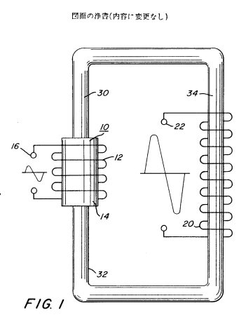
The first and second objectives are achieved by utilizing the first coil’s magnetic field and the particle acceleration element (sensor 10), plasma detection device 14, and voltage detection chip 16. These components are part of a system designed to generate charged particles inside the tube, using the magnetic coil to accelerate particles.
Additionally, the second coil 20 is installed along the outer part of the tube and interacts with the first coil to create a plasma acceleration effect.
By using voltage taps 22, electricity can be induced into the secondary coil 20, making the use of electricity possible.
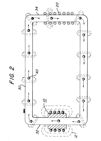
Magnetic element 40 is installed inside pipe 30, as shown in the second figure. This element 40 is free to move. When this element moves, it will float and separate charged particles in the plasma, expelling electrons and ions from the mixture. Additionally, it will further support the transition to the preferred state, ensuring that the particles in the plasma are properly separated.
As the particles move through the coils, acceleration increases, and this magnet accelerates the particles as they transition between different layers. The magnetic element and the particles work together to allow for smooth acceleration.
Furthermore, this movement creates a temperature drop, allowing the particles to reach maximum velocity. The interaction of the electric fields between the particles also changes as the input voltage increases or decreases, influencing the particle’s direction.
As a result, the voltage and current output of the secondary coil 20 will change. The output voltage/current of the secondary transformer coil 20 is influenced by the taps 22.
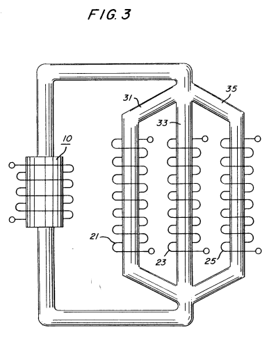
The only method for configuring this system is to use the loops 1 and 2. The secondary coil circuit in the third figure represents a combination of the charged particles. These particles are shown in the discharge tubes, forming magnetic fields in response to the plasma. Taps 21, 23, and 25 are attached to separate parts of the coil.
The coils with taps 21, 23, and 25 are connected to corresponding parts of the circuit, as shown in the first and second diagrams. The connected pipe releases the input-output energy, combining with the magnetic fields of the secondary coil to form a steady three-phase electric system.
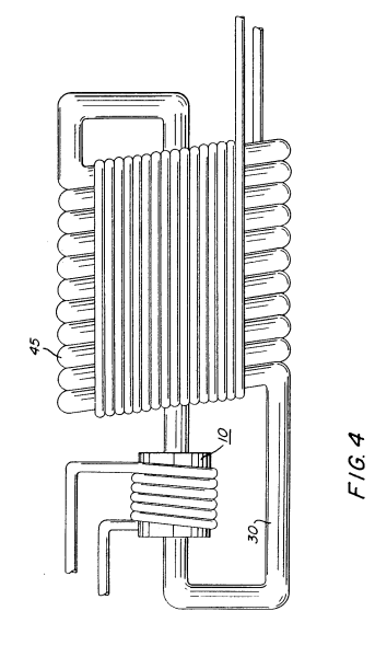
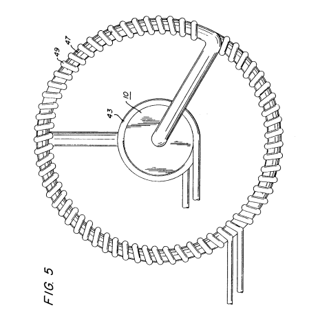
In the fourth figure, the charged particle system causes the charged plasma to be isolated physically in the magnetic fields to enhance the discharge system's overall performance.
The insulation coating 45 completely covers the entire electric coil and the pipe 30. Figure 4 shows that as the provided electric energy stabilizes, the coil windings increase, and the voltage/current power becomes stronger.
The physical properties of water, such as the dielectric constant and the surface tension of hydrogen, are effectively utilized in this configuration. As a result, large-diameter pipe-based secondary current transformers with multi-turn coil windings are used.
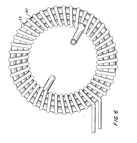
Figure 6 explains the general layout, with the central particle accelerator tube 41 utilizing the entire particle acceleration structure. The device works by using the primary and secondary coils inside a two-phase structure with coil windings. The taps 53, installed in alignment with the coil windings, form a structure of mutual interaction between the coils.
In summary, Figures 1, 2, and 3, combined with particle acceleration tube 41 and pipe-based structures, enhance the entire system’s efficiency. Additionally, coil windings are placed in parallel rows, with each part of the system holding a crucial role in generating power.
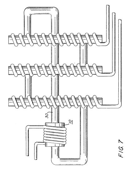
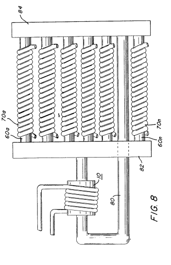
There are three secondary coil windings, and tube 30 passes through all three of these secondary windings in a straight arrangement. Figure 7 illustrates the structural configuration of the coil windings. The windings of the pickup coil are lined up in a straight arrangement, with tube 80 running through them in a linear path. The principle of these windings is based on a numerical setup with 7600–60nC indicating an output capacity of 88 and providing a distance ratio of M84 on the coil. The secondary coil windings 70A and 70B are arranged in series, respectively connected to the device.
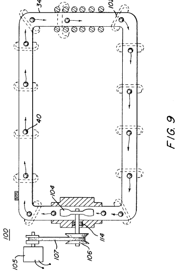
The particle acceleration tube 104 is installed along with its particle accelerator tube 110 to create a primary structure. Figure 9 shows that the particle acceleration device achieves speeds of 1100 meters per second. In this implementation, the particle device 102 is enclosed within the magnet tube 110, and the detector magnet sensor 106 reads the magnetic field produced. The energy acceleration tube 104 increases the power and, through the coupling system, adds frequency modulation using device 112, combined with the recalibration system 114 located at position 102.
When particles rotate around the secondary coil, electrical power/voltage is generated in the secondary coil. This suggests that particles do not just revolve around the coil but also induce electromagnetic cutting in the coil's magnetic field.
As previously explained, pipe 30 is a non-magnetic pipe. This is important as this pipe cannot have magnetic properties. Furthermore, pipe 30 provides the capability to rotate through a certain rotational mechanism. This rotation induces electromagnetism, and these rotating particles are the source of this phenomenon.
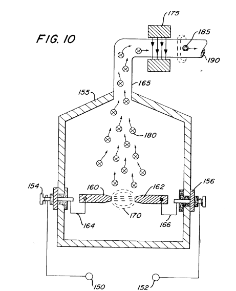
The next part explains various embodiments of the coil winding concept. In one embodiment of this invention, the coil is surrounded by a sealed magnetic tube, which generates electrical power/voltage in the coil. Figure 10 shows the electrical generation and winding process, designed to adjust to various operational steps while increasing the magnetic and inductive capacity.
Channel 155 is made of magnetizable (magnetization-capable) material and serves as the magnetic core.
When voltage 160 is applied to particle 162, the charged magnetic particle escapes from the magnetic pole and moves upward to particle 180. Particle 180 is elevated into a non-magnetic space, and when the magnetic field force is applied to each particle, it passes through magnetic element 175. All the magnetic charges pass through the demagnetizing coil 185, reaching the magnetic generator unit 190.
In the above mentioned embodiment and the simplified illustrations shown in Figures 1 and 2, the rotational acceleration rate is increased by adjusting the input of each particle into the magnetic core. This rotational input is proportional to the secondary voltage/current power output and sent to the voltage power capacitor 200. This is an important feature of the present invention.
The advantage is that voltage conversion is performed depending on whether the input voltage is DC or AC. When the input voltage is DC, the output voltage will also be DC. On the other hand, when the input voltage is AC, the output voltage will be AC. Furthermore, when a pulse voltage is used, a pulse output voltage will be generated. In this way, the present invention adjusts the input voltage and outputs the desired voltage based on the type of input voltage used.
As described in the preferred embodiment above, this invention may vary depending on the scope of the claims and modifications as outlined in section 4.0 below.
Section 4.0 illustrates the principles of the invention through partial diagrams. Figure 1 shows a typical three-phase system circuit configuration of the present invention. In Figure 3, another preferred embodiment of the invention is shown with an extended circuit design. This configuration includes separate systems for each voltage input.
Figure 9 explains a different configuration for the magnetic acceleration device to generate magnetic particles. Figure 10 shows the magnetic particle generator configuration used in the present invention.
Figure 10 Particle Acceleration Device
Tap Method 20, 21, 23, 25, 53, 70 ~ 70n...
Second Coil Winding Line 30, 31, 33, 35, 47...
Non-Magnetic State Coil 102, 180...
Magnetic Element 106...
Particle Acceleration Process 150, 152...
Voltage Power Supply 155...
Channel 160, 162...
Magnetic Material Manufacturing 165...
Pipe 175...
Magnetic Particle Generator
Procedure Amendment Document (Form)
Date: Showa 58 (1983) June 30Patent Office Document Number
Showa 58 Year Application Number 23664
Title of the Invention: Electric Particle GeneratorApplicant for Amendment: Submitter:Name: Stanley A. Meyer
Agent: Address: Tokyo Chiyoda Ward Iidabashi 3-Chome, Number 1-1(Law Firm Name and Phone Number)Name: Attorney Nakamura Tetsu (Registration Number 5995)
Date of Amendment Order: Showa 58 (1983) May 31
Content of Amendment: Full diagram revision
Details of Amendment: As per the attached diagram, the diagram content has been changed.
|
|
|
|
|
|
|
|
|
|
|
|
|
|
|
|