Literature Analysis
SECTION ONE OVERVIEW:
SECTION ONE NOTES:
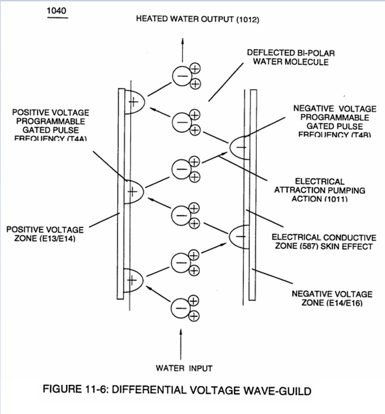
Stan mentions: “a singular unipolar voltage pulse wave-form alternately polarity triggered” is yet another way to release thermal energy from the water molecule.
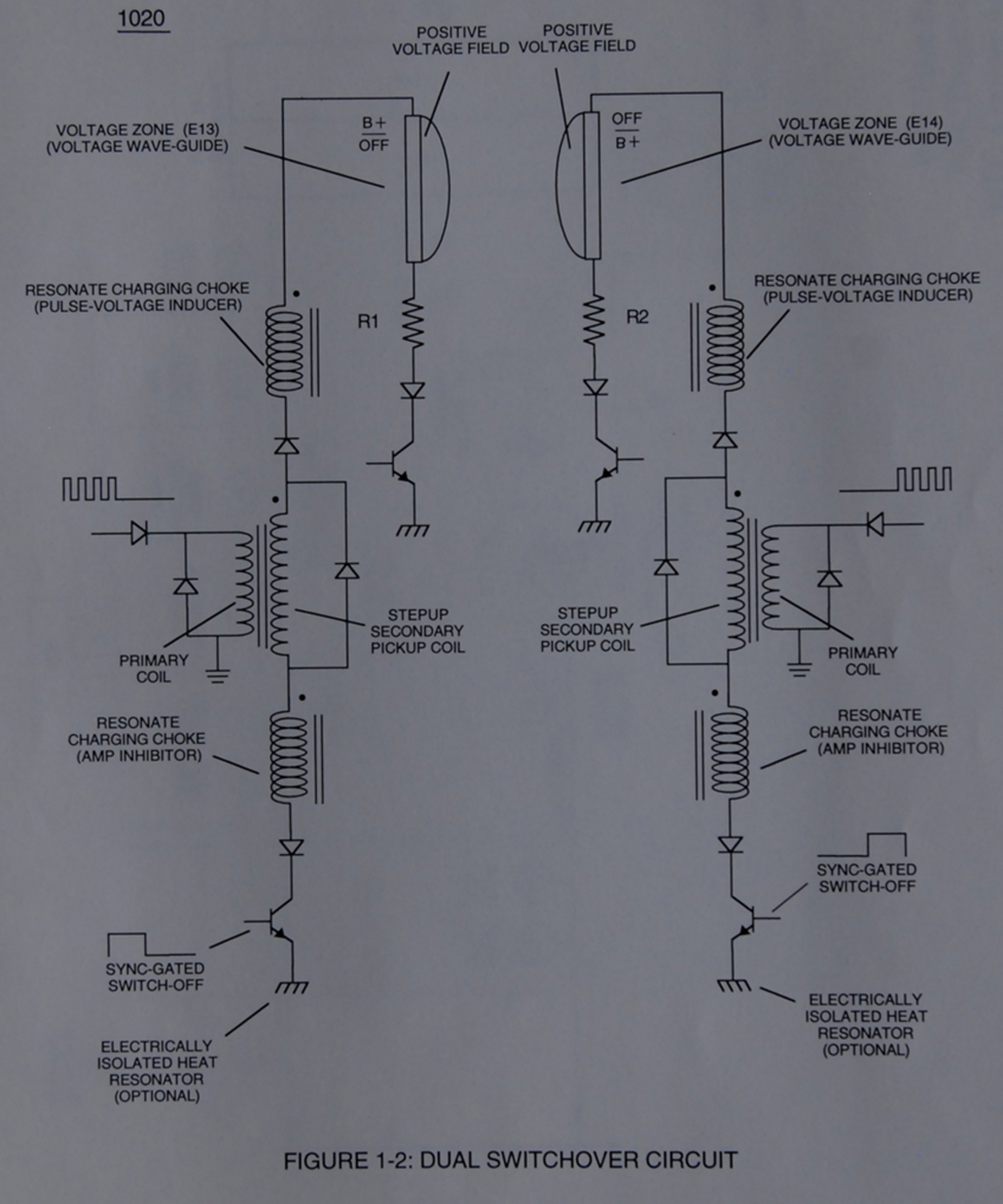
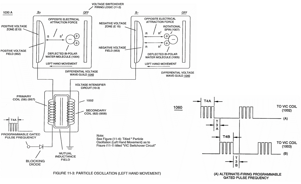
- This statement indicates that only one pulse train is utilized, but has electronics that controls the polarity by connection to VIC coil array. The pulse train diagram referenced matches up when superimposed to provide clarity. It appears the T3A/T3B are the transition delay times of the switching between primary coils.
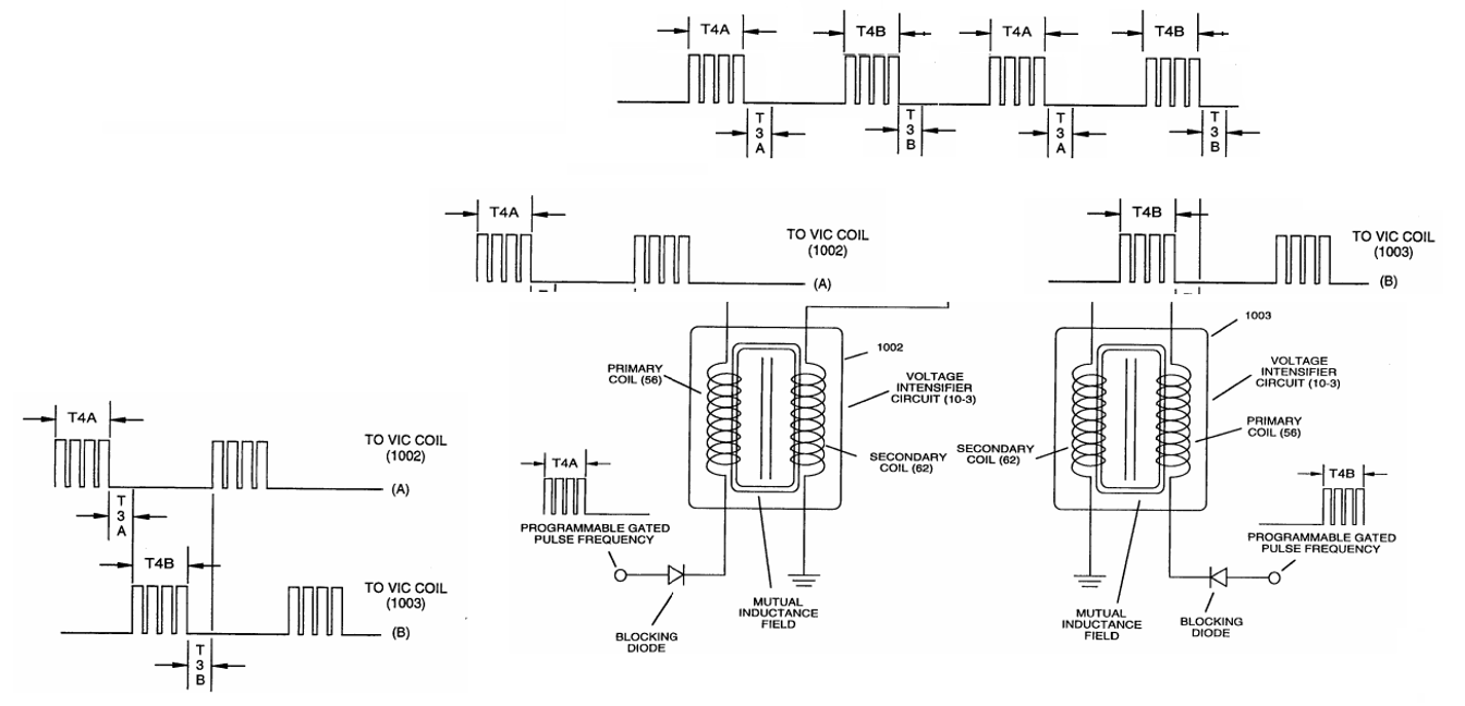
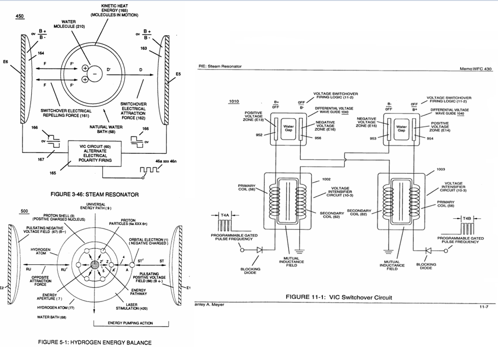
Figure 3-46 shows a setup that indicates bipolar pulse train applied (noticing the voltage is diagrammatically shown in reference to 0v, or ground). This would provide a greater difference of potential, being that the total electric field gradient would be the summation of peak-to-peak voltages. The waveform above could be utilized still. The change being the orientation of VIC primaries, to 180 degrees out of phase with one another, and provide a center tap for 0v.
SECTION TWO OVERVIEW:
SECTION TWO NOTES:
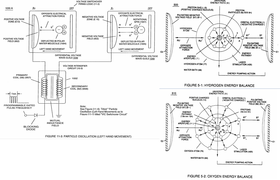
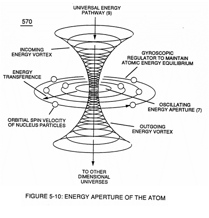
Meyers mentions: “causing atomic flexing of the water molecule atom(s) energy aperture (7) of Figure (5-1) which, in turns, releases radiant thermal heat energy (165) from atomic structures. While Meyer doesn’t expressly mention this diagram (Figure 5-10), it is helpful to understand the inter-atomic actions.
We can see that “Oscillating Energy Aperture” is designated as (7). This correlation to above excerpt cannot be ignored. Clearly, Meyers is talking about the electrical field causing a flexing or elongation of the atom down to nuclear level. Should also remember that radiant thermal energy is in the form of photons (according to physics). These are the exchange of electromagnetic energy, or heat. Flexing orbital pathways may cause photon emission as electrons are forced to upper/lower energy levels.
SECTION THREE OVERVIEW:
SECTION THREE NOTES:
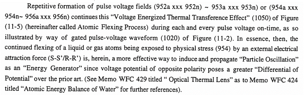
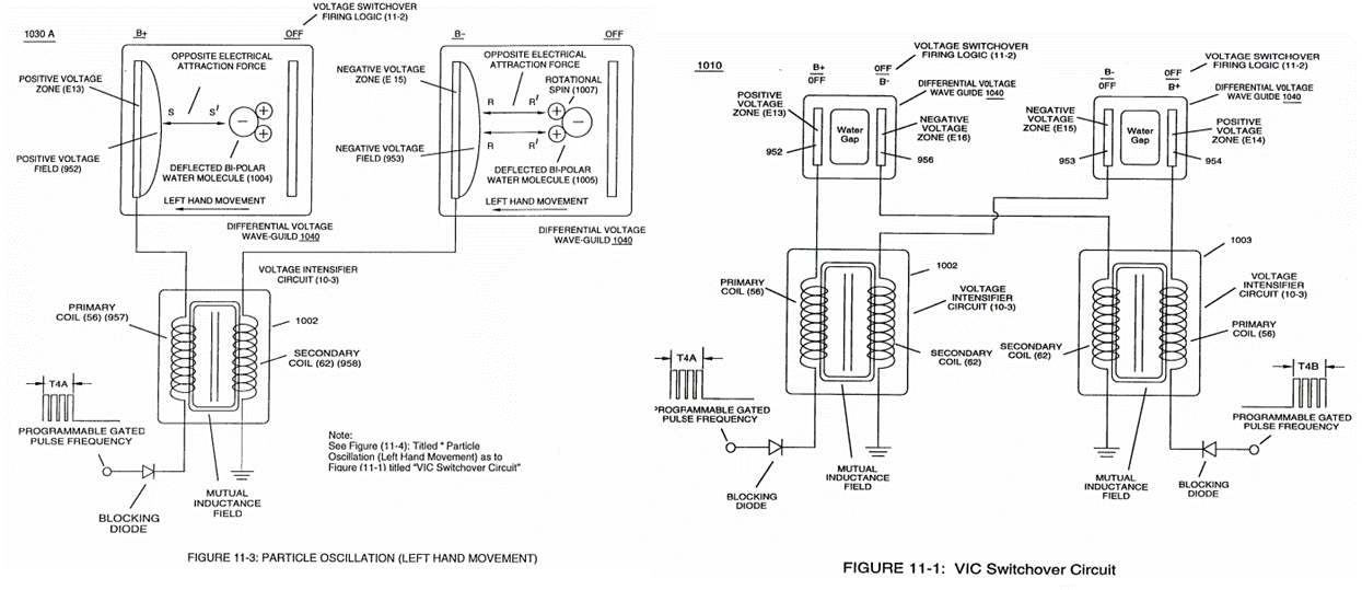
A reference is made here to “1020” of Figure 11-2. There is no such labeling. This indicates that this is an edit of original connotation.
SECTION FOUR OVERVIEW:
SECTION FOUR NOTES:
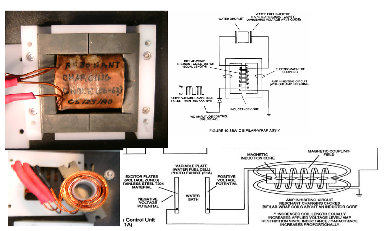
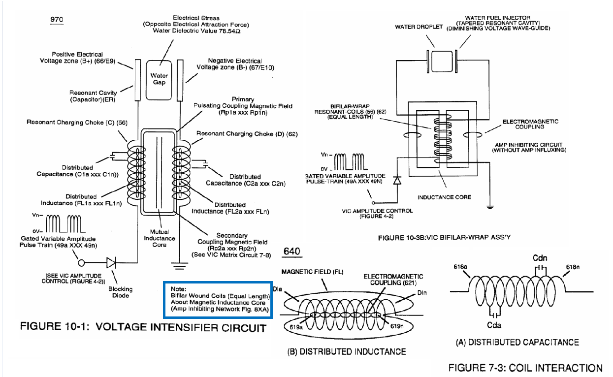
Meyers goes on to cover how the amp restriction effect occurs via self-inductance coupling. This in simple terms means as the current rises due to applied potential in the primary coil, its magnetic field starts to grow outward, cutting the adjacent winds next to it. This induces a counter-EMF which acts as a retarding force against the magnetic field that originated (lenz law essentially). The inductance of each coil, divided by its equivalent series ohmic resistance will provide the conventional 5-time constants required to determine maximum current to flow and counter opposing voltage to be overcome which would mean current not longer is in a transient state. This “Choking” effect retards current (electron) movement in a dead short condition without consuming power since energy is stored as a magnetic field.
When pulsing/rising current flow is shut off (no later than before 5th time constant) the stored energy within magnetic field rapidly collapses, causing a voltage spike to be generated that is exponentially higher than the source. It must be understood this self-inductive, current retarding effect is the “choking” phenomena Meyer’s references when limiting current in a dead short condition. 50/50 duty cycle pulse train is easier to control this energize/de-energize than a variable duty cycle, since self-inductance causes a RC like curve to form and variable duty cycles would be negatively impacted. Gating allows a certain number of pulses to energize/de-energize/energize….etc to produce this build/collapse effect within a given time period (gate frequency).
Meyers then references distribute capacitance being the cause for elevating of the applied voltage level to a higher voltage amplitude. The bifilar geometry of the coils facilitates this. To get an excellent description of this effect, please reference Nikola Tesla’s patent # 512,340. It should be understood that each pair of parallel wrapped wires has a dielectric between them. This is a capacitor by definition. Picture tiny capacitors in series for the number of parallel pairs. Capacitor’s voltage level is increased in a series configuration, while energy storage is reduced proportionately. However, when we connect the termination of coil 1, to the beginning of coil 2 (which is the correct connection method, not the one shown up above), the difference of potential is greatly magnified. This is because 180 degree opposed windings would produce an equivalent peak-to-peak voltage summation for each winding pair, times all the distributed capacitance sections.
With this overview, it should be understood that within the inductors, we have a current choking effect, as well as a different of potential (high voltage) storage/source phenomena. The diode is a critical part in producing the step charge also.
SECTION FIVE OVERVIEW: