Steam Resonator - 3D printable replication
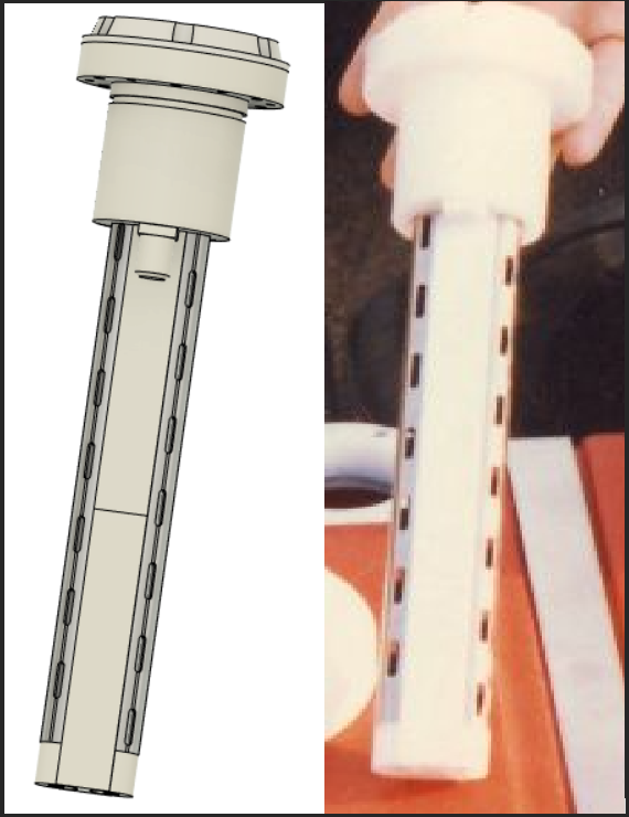
As of 5-3-23 the STLs shown in here are being printed to build a plastic model. At this point, please only consider the following as informational and do not print until all parts are verified to be correct.
TOP CAP:
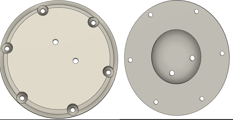
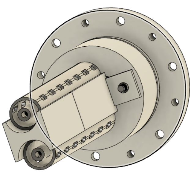
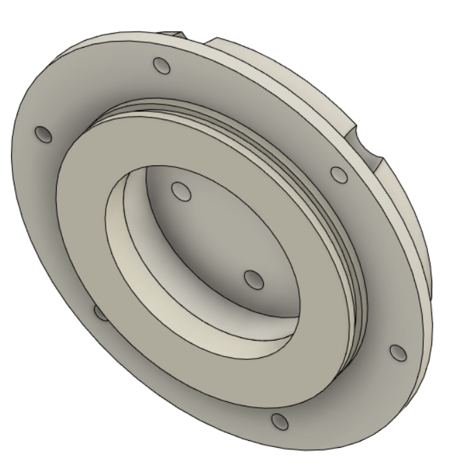
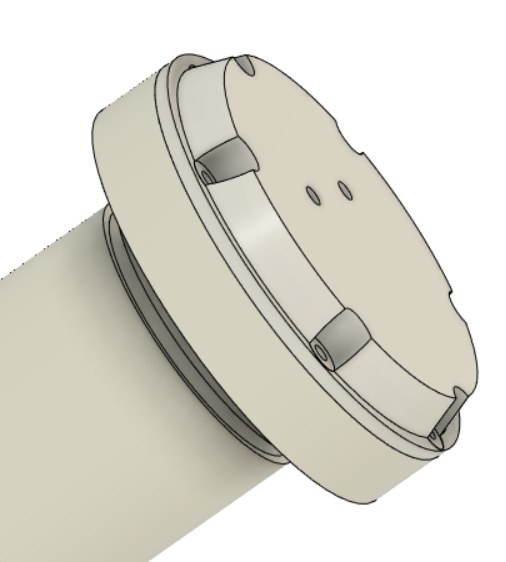
Top cap is as the name implies. Screw holes are located around the periphery for mounting inside a water tank. Two holes for electrical connections can be seen near the center.
ORING:
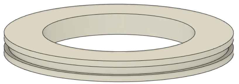
This piece is to be glued to the top cap to accept a sealing O-ring. The STL is for two half pieces that need to be glued together.
S/R MOUNT BASE:
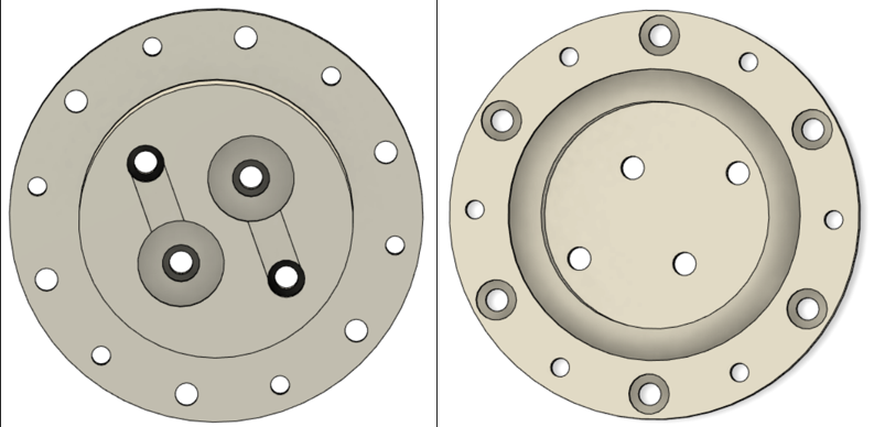
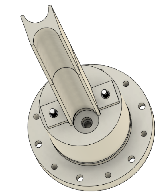
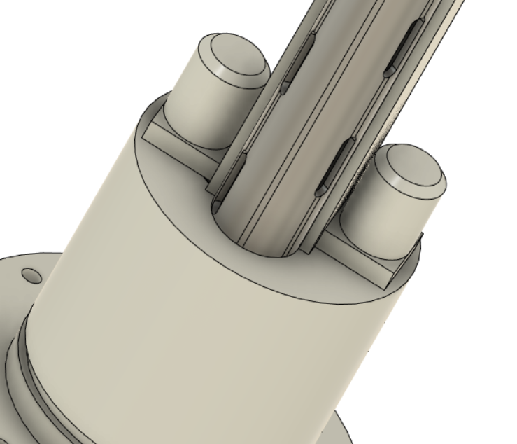
The S/R block is the area that the coaxial orientated electrodes are recession into. This allows electrical connection at the top.
Steam Resonator SR Mount Base.stl
OUTER ELECTRODE:
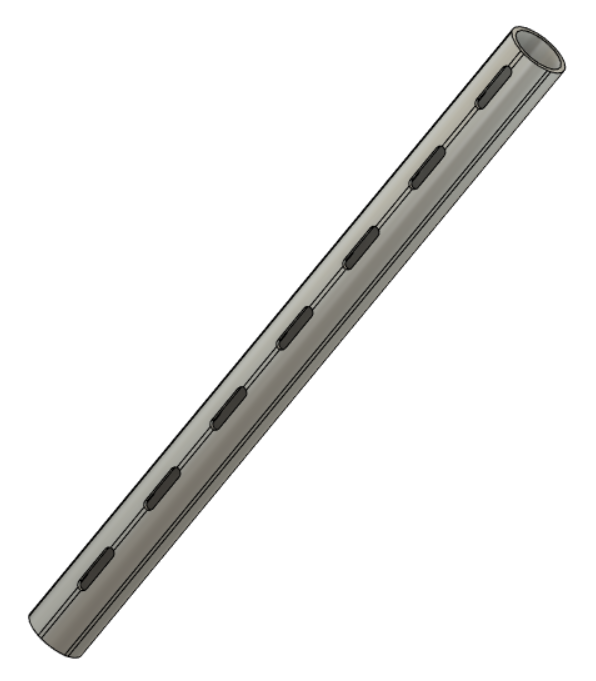
Outer electrode is T-304 stainless steel tube. 0.625" outside diameter. 0.049" wall. 0.527" inside diameter. 7.725" long. Since machining slots could be difficult and costly, a stencil was made (two half pieces for easier printing) that slides over a .625" diameter tube for marking and manual machining. Stencil STLs are listed below.
Stencil: RESONATOR MILLING STENCIL TOP SECTION.stl , RESONATOR MILLING STENCIL BOTTOM SECTION.stl
INNER ELECTRODE:
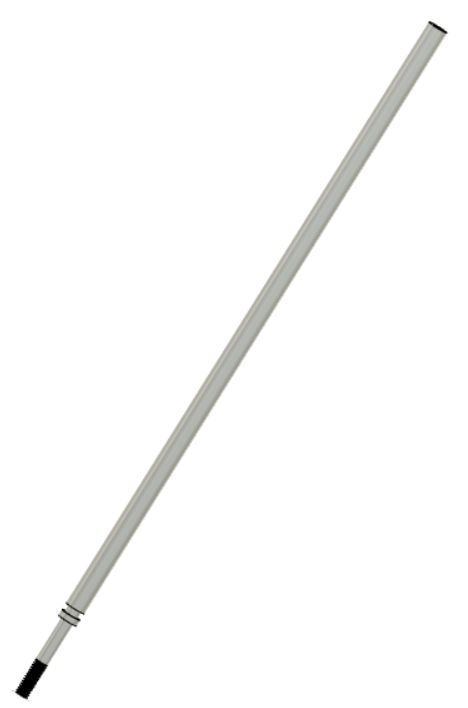
The inner electrode is T-304 stainless steel material. 0.25" outside diameter. 9.165" long. Machining will need to be done per the drawings.
INSULATION BLOCK:
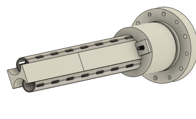
The insulative block is an insulation divide between the two outer electrodes. The overall length is 8.125". Square section is .150" tall. Given the length of the whole piece, STLs are half pieces that need glued together.
Insulative block 4.125_ section .stl
Insulative block 4.00_ section .stl
DELRIN NUT:
Delrin nut goes over the shorter threaded protrusion of the mounting pins through the insulative block
Steam Resonator Delrin Nut .stl
MOUNT PIN:
END CAPS:
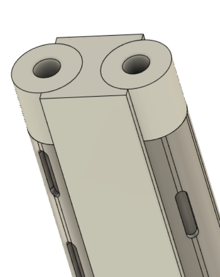
Delrin end caps that have a .300" recession for the inner electrode, and .100" protrusion for inserting into inner diameter of outer electrode.
STEM PLATE:
ASSEMBLY:
FIGURE 1:
Place the mounting pins into their respective recessions. The longer threaded portion goes up through the SR block. Shorter threaded ends go downwards through the insulative block's .150" square section.
FIGURE 2:
Insulative block is placed over the mounting pin's protrusions.
FIGURE 3:
Outer electrodes, with welded stem plates, are recessed into their corresponding holes (.200" recession into SR block).
FIGURE 4:
Place inner electrodes coaxially inside the outer electrodes. This is accomplished by recessing them into the SR block (.420" recession).
FIGURE 5:
End caps are placed onto the bottom. There is a .100" protrusion on the end caps that goes into the inner diameter of the .625" diameter tube. Through the bottom of these end caps, 6-32 stainless steel screws are secured.
FIGURE 6:
Screw the delrin nuts (.500" outside diameter) onto the mounting pin threaded protrusions to secure the insulative block.
FIGURE 7:
Secure the O-ring support via glue to the underside of the top cover.
FIGURE 8:
Place top cap onto SR block.

