Gas Electrical Hydrogen Generator #4,613,304
United States Patent Patent Number: 4,613,304
Date of Patent: September 23, 1986GAS ELECTRICAL HYDROGEN GENERATOR
Inventor: Stanley A. Meyer, 3792 Broadway, Grove City, Ohio 43123
Filed: November 5, 1984
Application No.: 668,577
PDF Download: Meyer #4,613,304 Gas Electrical Hydrogen Generator.pdf
Abstract
A hydrogen gas generator system for converting water into hydrogen and oxygen gases, in combination with a magnetic particle accelerator for voltage/current electrical potential generation. The hydrogen gas generator encompasses an array of plates immersed in a housing and having natural water pass therethrough. Direct current, voltage dependant/current limited, potential applied to the plates causes the hydrogen/oxygen gases to disassociate from the water molecule. The upper portion of the container is a hydrogen/oxygen mixture collection chamber for maintaining a predetermined gas pressure. There is introduced into the hydrogen/oxygen collection chamber, from a source, a substantial quantity of permanently magnetically polarized particles. Attached to the gas collection chamber outlet is a non-magnetic, non-conductive closed loop of tubing. The polarized magnetic particles are caused to circulate in the closed loop tubing by an electrical and/or mechanical pump. A pick-up coil wound around the tubing will have a voltage induced therein as the magnetic field of the polarized magnetized gas particles pass therethrough. The induced voltage has utilization as an electrical power source. In that the hydrogen/oxygen gases are not polarized the gases will seek a pressure release via an outlet. The hydrogen and oxygen gases may be utilized such as in a burner system.
GAS ELECTRICAL HYDROGEN GENERATOR
This is a continuation-in-part application of Ser. No. 435,889, filed Oct. 21, 1982 now abandoned.
CROSS REFERENCE AND BACKGROUND
There is disclosed in my co-pending patent application, filed Sept. 16, 1981, U.S. Ser. No. 302,807, for Hydrogen Generator, a hydrogen generating system for a water bath having immersed therein an array of plates. The hydrogen and oxygen atoms are disassociated from the water molecule by the application of a regulated, non-filtered, i.e., voltage/current limited potential to the plates having natural water pass therethrough. The plates, as well as the housing, are non-oxidizing, non-corrosive, non-reactive, and of similar materials.
In my co-pending patent application, Ser. No. 411,797, for Controlled Hydrogen Gas Flame, filed Aug. 25, 1982, there is disclosed a hydrogen gas burner. The nozzle in the burner is connected to the storage container. The nozzle has an opening of a controlled size and configuration, related to the size of the flame and the refractive and velocity of the burning gas mixture.
Also, in my co-pending patent application, Ser. No. 367,061, for Electrical Hydrogen Generator, filed Apr. 4, 1982, there is disclosed an electrical generating system that is utilized in combination with the aforesaid hydrogen/oxygen generator.
OBJECTS
It is a principal object of the present invention to provide a hydrogen gas electrical generator capable of producing a voltage/current, much greater in magnitude heretofore possible.
Another object of the present invention is to provide such a hydrogen gas electrical generator utilizing magnetized elements and wherein the magnetized particles are accelerated in a closed loop tubing to induce a voltage/current much greater than heretofore possible.
An additional object of the present invention is to provide such an electrical generator in combination with a hydrogen/oxygen gas generator that is responsive to a simplified on-demand electrical generator.
SUMMARY OF INVENTION
The present invention utilizes the basic principle of inducing a magnetic current in a pick-up winding by passing a magnetized element in close proximity to the winding. In the present invention, a hydrogen/oxygen gas generator, in combination with an electrical generating system, provides for the on-demand generation of hydrogen/oxygen gases and the immediate utilization of the gases to provide electrical power.
The hydrogen gas generator encompasses an array of plates immersed in a housing and having natural water pass therethrough. Direct current, voltage dependent/current limited, applied to the plates causes the hydrogen/oxygen gases to disassociate from the water molecule. The upper portion of the container is a hydrogen/oxygen mixture collection chamber for maintaining a predetermined gas pressure. There is introduced into the hydrogen/oxygen collection chamber, from a source, a substantial quantity of permanently magnetically polarized particles. These particles are caused to circulate in the closed loop tubing by an electrical and/or mechanical pump. The magnetic fields of the polarized particles provide an attractive force for moving the polarized particles through the closed loop tubing. As the particles circulate through the closed loop tubing, a voltage is induced therein. This voltage has utilization as an electrical power source.
BRIEF DESCRIPTION OF DRAWINGS
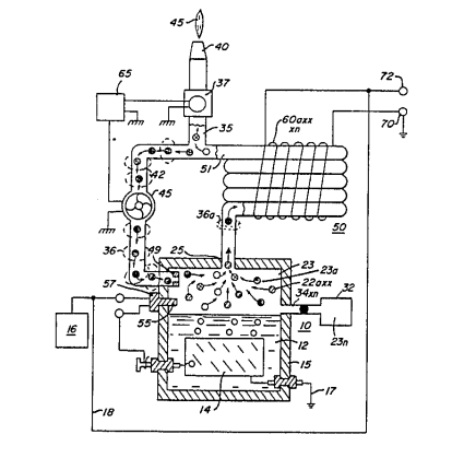
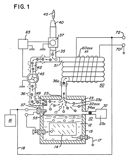
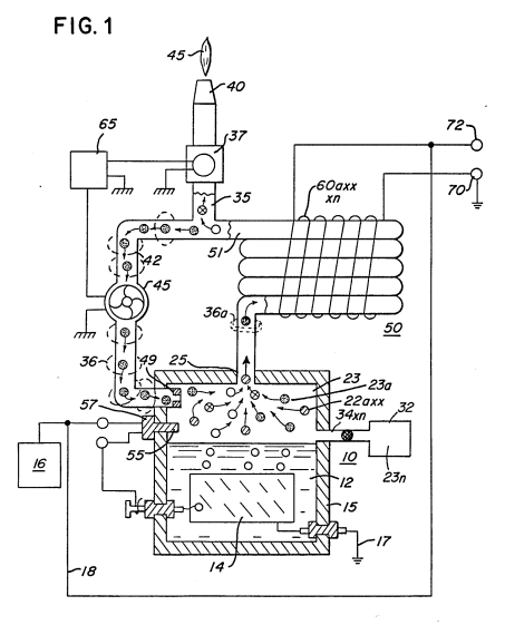
FIG. 1 is a simplified illustration of the principles of the invention, in cross-section showing the electrical generating means in combination with the hydrogen generator in a preferred embodiment.
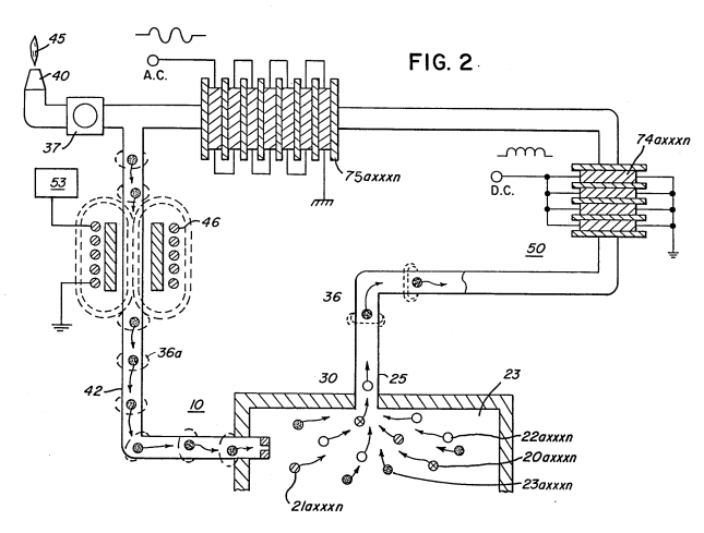
FIG. 2 is a magnetic particle binding ring, in an electrical schematic circuit arrangement, illustrating the induced direct and alternating current voltage.
 |
DETAILED DESCRIPTION OF DRAWINGS
Referring now to FIG. 1 there is illustrated the invention in a preferred embodiment in a simplified schematic arrangement. The generator 10 comprises an airtight pressure housing 12 of non-corrosive, non-reactive, non-oxidizing material. The housing 12 is filled with natural water 15 or a predetermined level, immersed in the water 12 is an array of plates 14.
In the preferred embodiment of the invention of FIG. 1, as disclosed in my co-pending application Ser. No. 302,807, the plates 14 are formed of an appropriate water flow, non-oxidizing, non-reactive material. A variable non-pulsed, voltage applying relay 17 connected to the plates 14 applies a steady d.c. current to the plates 14 which dissociates the water molecule as the natural water flows between the plates. An appropriate non-magnetic insulating material surrounds the plate configuration. Hydrogen/oxygen gas is formed and rises to the upper collection area 23 in the form of a hydrogen/oxygen gas mixture.
The gas collection area is connected by appropriate non-magnetic tubing 20 to the gas collection chamber 23. The chamber 23 is closed and connected to an outlet valve 27. A magnetic particle pump is utilized to pump the polarized magnetic particles through the closed loop tubing 24. These particles create a voltage in the windings 30 as they pass through the accelerator chamber 34.
The output voltage/current is utilized via terminals 70a-72.
As aforesaid, the storage chamber 23 is maintained at a predetermined pressure, and once the pressure is attained the hydrogen/oxygen gases will be expelled into outlet line 25 with a substantial velocity. The pressure releases and maintains consistency through the entire loop arrangement of storing gas.
Upon demand for the flame, (such as for burning) from demand circuit 66, the valve 37 is opened causing the 10 gases circulating in closed loop line 24 to be released into the nozzle 40 and provide the flame 45 for ignition.
The hydrogen/oxygen gases leave the particles suspended through this system and the magnetic fields hold the fields of polarized particles via the attractive force, the motion of the polarized particles through the closed loop 78 will be greater than the gas stream of hydrogen/oxygen. This will enable the oxygen from the hydrogen/oxygen gas as well as separate themselves from the polarized particles. The hydrogen/oxygen gases will go via 35 to nozzle 40 whereas the polarized particles will continue to circulate through the closed loop. The chamber 37 further includes the main system 75 with the electrical source 16 to the generator system as the pressure in the chamber 23 sensed by pressure sensor 69 achieves a predetermined level.
By this description of the hydrogen generator as a burner, as disclosed in the co-pending patent application Ser. No. 411,997, the outlet tube 26 is connected to 30 directly to the nozzle 40 to obtain the flame 45 upon ignition. The operation of the gas burner is not altered in the present invention.
The housing 15 further comprises an inlet 34 having 35 a chamber 33 of substantial amount of permanently polarized magnetic particles size 30X36. The chamber 23 superimposes the non-electrically conducting gas and hydrogen/oxygen gases.
Upon demand, as set forth before, the opening of the 40 valve 37 causes the pressurized differential with the gases circulating in the chamber 23. In this way the gases being the polarized particles superimposed therein will be greater released and caused to enter the closed-loop 50.
The gases will have accelerated gas 45 maintain in a continuous motion circulating through the closed loop.
The magnetized particle 35 is a series of loops of non-conducting tubing 25 wherein the tubing configuration in an enclosure is in spaced relationship of 50 magnetic induction units.
In the illustration the gas maintaining its superimposed polarized fields is the key for obtaining high-energy use in many of these systems as will be understood.
The gas enclosed in this chamber is critical as it is not operating as the system for the current usage of 35. It is critical for the same expansion of this model 35, however upon entry into the nozzle 40 it can be placed for use.
Upon satisfaction of demand, the valve 37 will close and thereby close the current circulating through closed-loop 24. In this arrangement the chamber 23 via closed-loop line 42, this arrangement the pump 45 will continue to operate and cause a continuous circulation of the polarized particles through the closed loop. Upon cessation of demand of current, the pressure release will shut off the system via 74.
The hydrogen/oxygen gas mixture demand circuit generates the superimposed polarized magnetic particles. The pump 45 is continuous upon this as a part of the continuous operation of the hydrogen/oxygen system.
The magnetized particle source 32 is operative on demand in the main generator assembly to maintain this system. The hydrogen/oxygen gases are superimposed through a nozzle 45 generating this flame system in the hydrogen/oxygen gas.
Referring now again to FIG. 1 there is illustrated initially a schematic system of this combination of demand, electrical control, and output of power.
Initially it is noted that the pump 45 of FIG. 1 has been replaced by the electrical particle accelerator 46. The accelerator 46 is non-mechanical, no moving part element and therefore not subject to wear. It is to be recalled, polarized particles have been placed on the magnetic particle accelerator 46 for the magnetic particles to be forced along the accelerator and they are to 40 pass through the center of the accelerator where they feed the system.
The accelerator system of FIG. 2 is used in FIG. 1 for the acceleration of 46-FIG. 2 may be utilized as both the induced current voltage, or alternating current winding on 60.
Both the accelerator 46 and the pump assembly 45 with reference to FIG. 2 illustrates the simplicity of the electrical system to induce the voltage for maximum usage as the 10 main winding 64 on alternating windings wound in parallel for obtaining an electrical field.
The combination electrical field generates the polarity needed and magnetized with the voltage is utilized on pickup coil windings via the pump.
With reference to FIG. 1 with continued reference applied to the plates 14 a direct current voltage. The voltage applied to the plates 14 from power supply 16, depending upon the demand circuit, will vary the intensity of the flame 45, the voltage of the generator, and the output.
Further, as specifically repeated, the voltage is current limited. Accordingly, the power source 16 will provide circuitry for varying the voltage to the plates 14 and for restricting the amperage to a negligible value relative to said voltage.
voltage applied to the plates 14 from power supply 16, depending upon the intensity of the generator, may be a variable voltage. For instance, if it is desired to vary the intensity of the flame 45, the voltage at the plates 14 will be varied.
Further, as specifically repeated, the voltage is current limited. Accordingly, the power source 16 will provide circuitry for varying the voltage to the plates 14 and for restricting the amperage to a negligible value relative to said voltage.
In a self-sustaining embodiment of the gas electrical generator, a portion of the output at the voltage taps 70–72 of the pickup coils is directed back to the power supply 16. In that the total power requested to be applied to the plates 14 is relatively low, an insignificant portion of the output at gas taps 70–72 is required for sustained operation of the system.
The electrical particle portion of the electrical gas generator of the present invention is operative continuously as set forth above. Hence the output voltage at gas taps 70–72 will be available to the power supply 16 whenever a demand for gas generation is made.
I claim:
- In combination, a hydrogen/oxygen generator comprising:
a hydrogen/oxygen generator including a housing having a gas collection chamber for maintaining a preset volume of gas therein under pressure, an outlet attached to said collection chamber, a non-magnetic tubing connected to the other end of said gas collection chamber and said collection chamber in a closed loop,
utilization means, and
a Y type of connector alternately connecting said gas line tubing to said utilization means and said collection chamber,
an inlet means attached to said gas collection chamber,
a source of permanently magnetized polarized particles connected to said inlet and wherein said particles are superimposed on said hydrogen and said particles pass through said tubing and said non-magnetic tubing connected to said hydrogen/oxygen gases.
- The combination as set forth in claim 1 further comprising:
two directional valve means, and
a demand circuit connected to said valve means for selectively closing and opening said valves so said utilization means and gases having superimposed hydrogen/oxygen particles pass therethrough,
a pressure gauge for determining the pressure in said collection chamber,
a non-magnetic means connected to said tubing means for maintaining the continuous motion of said polarized particles through said closed loop,
said polarized particles connected to the gas electrical generation system for acceleration of said particles for passing through said utilization means,
said collection chamber as defined and comprising:
a source connected to said direct current electrical source means for utilizing the frequency of said alternating current winding, and wherein said particles are magnetized as said hydrogen/oxygen gases enter said outlet.
- The combination as set forth in claim 1 further comprising:
a magnetic particle source, and
means for utilizing said polarized particles through the superimposition of said hydrogen/oxygen gases in said collection chamber.
- The combination as set forth in claim 1 wherein said utilization means comprises:
a liquid solution for circulating in said gas electrical generation system and superimposed on said hydrogen/oxygen gases in said tubing.
-
The combination as set forth in claim 1 wherein said gas electrical generator has magnetic particles arranged in a continuous loop around said tubing and wherein said magnetized particles are superimposed on said hydrogen/oxygen gases in said tubing.
-
The combination as set forth in claim 1 further comprising:
a variable voltage source having circuit means for generating voltage/current for energizing said alternating current winding means, and rectifying said alternating current winding voltage of said pickup coil to said voltage source.
 |
||
|
|
|


