Solar Heating System #3,970,070
United States Patent
Meyer et al.
Patent No: 3,970,070
Date: July 20, 1976[54] SOLAR HEATING SYSTEM
[76] Inventors: Stanley A. Meyer, 2931 Bryden Road; Stephen R. Gray, 2722 Allegheny Ave., both of Columbus, Ohio 43209[22] Filed: Sept. 3, 1975
[21] App. No.: 610,051
[52] U.S. Cl. ................................. 126/271; 350/96 B
[51] Int. Cl. ..................................... F24J 3/02
[58] Field of Search .................... 237/1 A; 126/270, 271; 350/96 B[56] References Cited
UNITED STATES PATENTS
1,951,403 Goddard .......... 126/271
1,969,839 Goddard .......... 126/271
2,213,894 Barry ............... 126/271
3,046,414 Sandness ........ 126/270
3,252,456 Bohn Jr. .......... 126/271
3,780,722 Swet .............. 126/270Primary Examiner — Kenneth W. Sprague
Attorney, Agent, or Firm — Cennamo Kremblas & Foster
[57] ABSTRACT
A solar heating system comprising a lens collector arrangement, an insulation area, and a storage section positioned in an enclosing structure, and an associated utilization means. The collector lens is an array of light guide lenses having internal high and low refractive surfaces. The array is contoured in a capping relationship over a focusing lens to provide an extremely high concentration of solar energy irrespective of the angle of the sun. The light guide lenses increase by several orders of magnitude the amount of solar energy striking the surface of the focusing lens. The focusing lens is a plurality of flat surface type of lenses stacked one over the other in spaced relationship and operable to concentrate the solar energy to a central region. Surrounding the perimeter of the plurality of focusing lenses in an array, in a "wall" configuration, of light guide lenses similar in construction to the aforesaid capping light guide lenses. The angle of the reflective surfaces of the capping lenses and the wall lenses is such as to receive and direct to the focusing lenses the maximum amount of radiation at all times of the day and season. The insulation area is positioned between the collector lens and the storage section to provide a convective barrier for the storage area without inhibiting the passage of solar radiation. The storage section is of a high absorptive material with an auxiliary conventional heat source.
SOLAR HEATING SYSTEM
CROSS REFERENCE
The "Light Guide Lens" of the co-pending application filed Sept. 3, 1975, by the same inventors herein and given Ser. No. 609,928, is that utilized in the present invention.
BACKGROUND
With the energy crisis created by the impact of the natural resources shortage, together with the anticipated depletion of the natural resources, a considerable amount of effort has been directed to other forms of energy. Although there are several other forms of energy, the emphasis has been placed on solar energy as the most logical heat source. Consequently, there are on the market many so-called solar furnaces.
These prior art devices generally comprise a focusing lens, a medium - either air or liquid - to be heated, in some instances a storage tank, and in other instances a reflective surface such as a mirror and/or a reflector.
Although these solar furnaces are operable and in certain instances commercially operable, they are not without their attendant disadvantages. Principally the problem area is a lack of a sufficient concentration system for the incident solar energy, directivity relative to the angle of the sun, and a storage system with a capacity to carry the system on cloudy days. The problem related to the concentration of the solar energy is with the lens and its reflecting surfaces and the response of the system to the low angles of the sun.
Further, the prior art systems generally utilize the solar radiation to heat either a liquid or air directly and then utilize the heated air or water for the intended purpose. Storage systems are much fewer and are of the indirect type, that is, the heated excess air or liquid is placed in a storage medium. These prior art storage systems are very simple in structure and somewhat crude. Very little advance in the art has been made with storage systems.
Although perhaps in some future period of time solar energy may be a complete substitute for other forms of energy, today solar energy, at best, is a supplement to or an alternate source of energy. Nonetheless, the failures of the prior art to recognize the practical usefulness of solar energy systems resulted in commercial systems that are extremely expensive but, yet, of only a minimal and questionable value.
SUMMARY OF INVENTION
The invention comprises in its most general aspects a unitary air/liquid tight cylindrical enclosure that houses a combination of components that are responsive sequentially to solar radiation. The system provides a heat source with a larger capacity and operable for an extended period of time over that of the prior art. Within the cylindrical enclosure, the components comprise in the order of operability a collector lens, an insulating area, and a storage section. Utilization means for effectively utilizing the heat generated is associated with the basic combination of apparatus.
The collector lens, the insulation area, and the storage section are serially joined together and housed in an air/liquid tight cylindrical (with appropriate vents) enclosure that is insulated against heat loss.
BRIEF DESCRIPTION OF DRAWINGS
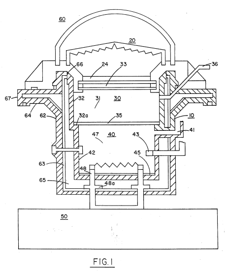
FIG. 1 is an overall schematic plan view illustrating the preferred embodiment of the present invention.
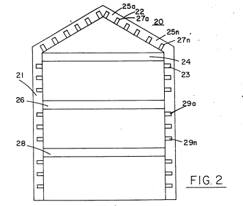
FIG. 2 illustrates a preferred lens arrangement shown generally as indicated herein for use of FIG. 1.
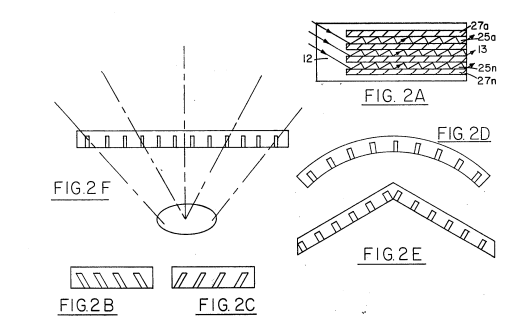
FIGS. 2A through 2F are various alternate embodiments of the light guide lens utilized in the present invention.
DETAILED DESCRIPTION OF DRAWINGS
With particular reference now to FIG. 1, there is illustrated schematically a preferred embodiment of the present invention. It is most fundamental form of a solar heater comprises a housing enclosure 10, light energy concentrator 20, an insulation area 30, a heat storage section 40, and a utilization means 50.
In principle of operation, the concentration lens arrangement 20 is capable of directing a maximum amount of solar radiation to its focusing lens. The solar radiation is directed to focusing lens from all angles irrespective of the position of the sun overhead or on the horizon.
The focused solar radiation passes through an insulation barrier 30 to a thermal storage section 40. The insulation barrier 30 has a dual effect: to either inhibit the passing of thermal radiation (convective barrier). Once solar radiation is converted to thermal radiation the "heat" is stored in the thermal storage section 40, depleted by the energy demands from 50.
In actual operation the storage section 40 is the heat source. With a given capacity and the extremely efficient solar energy storage and retention, an extremely large amount of thermal energy heretofore not possible with other solar systems is obtained.
The solar heating system described above has an extremely broad and practical utilization range. However, it is not intended as "primary" energy supply but rather as a supplement to the conventional power sources.
The invention allows for continued heat storage and transfer from this stored energy and release at pre-determined times, for instance, on cloudy days or after sunset.
In the event that the storage section should exceed a certain predetermined thermal gradient (such as can occur during extended periods of "sunny" days) a heat sink arrangement is provided for the storage section to dissipate the excess energy. Additionally, a shelter arrangement and temperature-controlled unit in a conventional manner is provided for the heat storage.
 The solar energy lens 20 of FIG. 1 is shown more explicitly (again schematically) in FIGS. 2A, 2B, 2C, 2D, 2E, and 2F as alternate lens constructions which may be used. The basic method for utilizing the lenses of the preferred embodiment is to position them similar to prior art, such as in U.S. Ser. No. 609,928 filed Sept. 3, 1975.
Basically, each light guide lens in this array comprises alternate high refractive (transparent) material such as glass or high refractive plastics.
The early lens 28 will receive the transmitted radiation from lens 26. Surrounding the lenses 24, 26, and 28 and the spacing therebetween is the light guide lens array 29. This lens 29, too, like the capping lens 22, is made up of high and low refractive (transparent and reflective) materials. Accordingly, in passing from lens 24 to 28, the solar radiation is confined to a shorter transition striking the reflective surfaces 29a such that the light guide lenses 22.1 direct the solar radiation to the surface of the focusing lens 24 and 28.
As indicated above, the angle of the solar radiation transmitted (passing to focusing lens 24) is dependent on the angle of the incident solar radiation, the wavelength of the solar radiation and the wavelength length of the guide (reflective surface). The light guide lens comprising the capping lens 22 are generally in the vertical or displaced from the vertical relative to the lens shown.
However, the light guides comprising the wall lens 28 are generally in both the horizontal and displaced from the horizontal relative to the angles of the sun. The primary direction of the wall light guides 22.1 in the vertical is displaced 90 degrees from the horizontal.
The light guides 26 and 28 are each arranged as flat surfaces with a high rate of absorption to solar radiation.
The primary function is to collect the solar radiation from the outermost edge and pass it inwardly, reflecting the solar radiation towards the central structure of the solar heating system.
The additional focusing lenses 26 and 28 in the preferred embodiment shown in FIG. 1 are similarly constructed to the capping lenses.
Referring again to the focusing of FIG. 1, the solar radiation focused by the focusing lens 24 is directed through the insulation area 30. The insulation area 30 is a sealed engagement with the insulator 33 comprising a pool of glass with insulating material such as salts 32. The purpose and function of the insulation area 30 is to prevent the heat energy from escaping during cloudy days or after sunset.
Particularly, the insulation area in the preferred embodiment is a liquid solution, such as a salt compound, and the heat converts the liquid solution into horizontal stratifications.
With the salt layer of the preferred embodiment, heat energy storage is maintained by the refractive material. The heat is allowed to accumulate over long periods of time during sunny days and released during cloudy days.
As indicated above, the solar radiation passes through a storage cavity filled with a liquid material or solution, such as salt. This material has a high rate of absorption to solar radiation. The stored heat is transferred for energy purposes during "off-peak" periods.
... given material having a high rate of absorption to the particular solar radiation that is desired. The lenses and salt pool provide the means for storing solar radiation.
 Positioned in the lower region of the thermal storage section 40 is the heat collector and extraction assembly 47. The solar heating array 67 is conventional and may take other known forms. Connected to both sides of the collector plates 47 is the conductive thermal transfer means which is connected to heat exchanger means 50. Heat expulsion is induced by a heat utilization means 50 also conventional and commercially operable.
The solar heater of the present invention is intended as the primary heat source and may be utilized for the home or commercially. The size of the unit, although its relative size to other solar units is most small, would be increased depending on the market area to be heated. However, with the extremely efficient collector lens 28 in reality, it is only the storage area that need to be increased. Alternatively, individual units can be modularly stored, distributed throughout a given area.
It is appreciated, of course, that there may be periods of time when the sun doesn't "shine" and this may be especially disadvantageous in the winter months when the days are the shortest. Realistically, the time solar heater system of the present invention, although having a much greater and effective storage system, cannot be operated indefinitely during these "dark" periods of time when the temperature of the storage system drops below a predetermined standard. An auxiliary heat source can be connected to automatically operate, or the solar heater system itself can be cut off from energy.
The overall construction of the solar heater of the present invention is rugged, durable, and economical. The preferred embodiment was chosen to be cylindrical with a semi-flat top lens. The advantage of this configuration is that the system does not have to follow the sun. The lens is equally operative with the sun at any given angle.
It is recognized, however, that in certain climates, where it is desirable to move the solar energy for other purposes or the lenses require more exposure, more exotic glass or plastic dome lens applications may be constructed. The cover 61 of FIG. 6 can be replaced, if desired, with the lens 62 in the preferred embodiment, which can comprise metal coverings with a corrugated outer portion that supports the solar radiation system, and the lens has a cover frame that supports the lens.
It should be understood that other forms of lenses, including glass or synthetic plastic materials, can be employed for the focusing lens 28, depending on the specific climatic region. The angle, refractive index, and focal length of the various lenses can be adjusted accordingly to the sun's intensity.
It is to be noted that the present invention is illustrative only and that other modifications may be had therein without departing from the true spirit and scope of the invention.
What is claimed is:
-
A solar heater, comprising in combination:
- A collector lens positioned in the topmost region of said enclosure, and said collector lens comprising an array of light guide lenses of alternating high and low refractive material and focusing lens.
- A sealed enclosure positioned in the lowermost region of said enclosure for confining a thermal storage area of high capacity and solar radiant energy to thereby convert said solar radiant energy to thermal energy, with insulating means positioned within said enclosure intermediate of said lens and storage area, said insulating area further comprising a container with a liquid solution therein that prevents solar radiation and an isothermal convection barrier.
- And an enclosure further comprising a liquid and air seal to said lens, insulating area, and storage section, with utilization means for utilizing said thermal energy in said storage section.
-
The solar heater of claim 1 wherein said collector lens further comprises a plurality of spaced focusing lenses in a stacked relationship.
-
The solar heater of claim 2 where said focusing lenses each comprise a series of light guide prisms optically displaced from each other in various angles.
-
The solar heater of claim 3 wherein said focused prisms and wall lenses, with respect to the collector lens array and wall lens, will receive solar radiation directed inwardly and accumulated in a central focusing area to uniformly distribute said solar energy from the sun.
-
The solar heater of claim 4 wherein the primary direction of each set of light guides for said upper and lower lens sections is in the vertical with respect to the horizontal surface.
-
The solar heater of claim 4 wherein said focusing lens is circular, and the prisms are spaced circumferentially in an equal distribution.
-
The solar heater of claim 5 where said stacked focusing lenses are spaced apart by alternate regions of high refractive light guides, and at least one wall lens 28 is utilized in stacked and focused relationship to the focusing lenses 24.
-
The solar heater of claim 1 wherein said storage section further includes an auxiliary heat source thermally activated when the storage temperature exceeds a predetermined level.
Illustrations
 |
