Solar Heating System #3,970,070
United States Patent
Meyer et al.
Patent No: 3,970,070
Date: July 20, 1976Here is the transcription of the patent page you provided:
United States Patent
Meyer et al.
Patent No: 3,970,070
Date: July 20, 1976[54] SOLAR HEATING SYSTEM
[76] Inventors: Stanley A. Meyer, 2931 Bryden Road; Stephen R. Gray, 2722 Allegheny Ave., both of Columbus, Ohio 43209[22] Filed: Sept. 3, 1975
[21] App. No.: 610,051
[52] U.S. Cl. ................................. 126/271; 350/96 B
[51] Int. Cl. ..................................... F24J 3/02
[58] Field of Search .................... 237/1 A; 126/270, 271; 350/96 B[56] References Cited
UNITED STATES PATENTS
1,951,403 Goddard .......... 126/271
1,969,839 Goddard .......... 126/271
2,213,894 Barry ............... 126/271
3,046,414 Sandness ........ 126/270 X
3,252,456 Bohn Jr. .......... 126/271
3,780,722 Swet .............. 126/270Primary Examiner — Kenneth W. Sprague
Attorney, Agent, or Firm — Cennamo Kremblas & Foster
[57] ABSTRACT
A solar heating system comprising a lens collector arrangement, an insulation area, and a storage section positioned in an enclosing structure, and an associated utilization means. The collector lens is an array of light guide lenses having internal high and low refractive surfaces. The array is contoured in a capping relationship over a focusing lens to provide an extremely high concentration of solar energy irrespective of the angle of the sun. The light guide lenses increase by several orders of magnitude the amount of solar energy striking the surface of the focusing lens. The focusing lens is a plurality of flat surface type of lenses stacked one over the other in spaced relationship and operable to concentrate the solar energy to a central region. Surrounding the perimeter of the plurality of focusing lenses in an array, in a "wall" configuration, of light guide lenses similar in construction to the aforesaid capping light guide lenses. The angle of the reflective surfaces of the capping lenses and the wall lenses is such as to receive and direct to the focusing lenses the maximum amount of radiation at all times of the day and season. The insulation area is positioned between the collector lens and the storage section to provide a convective barrier for the storage area without inhibiting the passage of solar radiation. The storage section is of a high absorptive material with an auxiliary conventional heat source.
SOLAR HEATING SYSTEM
CROSS REFERENCE
The "Light Guide Lens" of the co-pending application filed Sept. 3, 1975, by the same inventors herein and given Ser. No. 609,928, is that utilized in the present invention.
BACKGROUND
With the energy crisis created by the impact of the natural resources shortage, together with the anticipated depletion of the natural resources, a considerable amount of effort has been directed to other forms of energy. Although there are several other forms of energy, the emphasis has been placed on solar energy as the most logical heat source. Consequently, there are on the market many so-called solar furnaces.
These prior art devices generally comprise a focusing lens, a medium - either air or liquid - to be heated, in some instances a storage tank, and in other instances a reflective surface such as a mirror and/or a reflector.
Although these solar furnaces are operable and in certain instances commercially operable, they are not without their attendant disadvantages. Principally the problem area is a lack of a sufficient concentration system for the incident solar energy, directivity relative to the angle of the sun, and a storage system with a capacity to carry the system on cloudy days. The problem related to the concentration of the solar energy is with the lens and its reflecting surfaces and the response of the system to the low angles of the sun.
Further, the prior art systems generally utilize the solar radiation to heat either a liquid or air directly and then utilize the heated air or water for the intended purpose. Storage systems are much fewer and are of the indirect type, that is, the heated excess air or liquid is placed in a storage medium. These prior art storage systems are very simple in structure and somewhat crude. Very little advance in the art has been made with storage systems.
Although perhaps in some future period of time solar energy may be a complete substitute for other forms of energy, today solar energy, at best, is a supplement to or an alternate source of energy. Nonetheless, the failures of the prior art to recognize the practical usefulness of solar energy systems resulted in commercial systems that are extremely expensive but, yet, of only a minimal and questionable value.
SUMMARY OF INVENTION
The invention comprises in its most general aspects a unitary air/liquid tight cylindrical enclosure that houses a combination of components that are responsive sequentially to solar radiation. The system provides a heat source with a larger capacity and operable for an extended period of time over that of the prior art. Within the cylindrical enclosure, the components comprise in the order of operability a collector lens, an insulating area, and a storage section. Utilization means for effectively utilizing the heat generated is associated with the basic combination of apparatus.
The collector lens, the insulation area, and the storage section are serially joined together and housed in an air/liquid tight cylindrical (with appropriate vents) enclosure that is insulated against heat loss.
BRIEF DESCRIPTION OF DRAWINGS
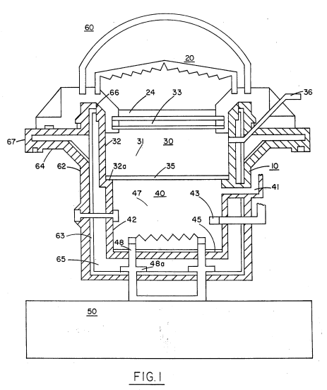
FIG. 1 is an overall schematic plan view illustrating the preferred embodiment of the present invention.
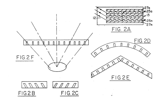
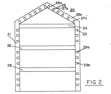
FIG. 2 illustrates a preferred lens arrangement shown generally as indicated herein for use of FIG. 1.
FIGS. 2A through 2F are various alternate embodiments of the light guide lens utilized in the present invention.
DETAILED DESCRIPTION OF DRAWINGS
With particular reference now to FIG. 1, there is illustrated schematically a preferred embodiment of the present invention. It is most fundamental form of a solar heater comprises a housing enclosure 10, light energy concentrator 20, an insulation area 30, a heat storage section 40, and a utilization means 50.
In principle of operation, the concentration lens arrangement 20 is capable of directing a maximum amount of solar radiation to its focusing lens. The solar radiation is directed to focusing lens from all angles irrespective of the position of the sun overhead or on the horizon.
The focused solar radiation passes through an insulation barrier 30 to a thermal storage section 40. The insulation barrier 30 has a dual effect: to either inhibit the passing of thermal radiation (convective barrier). Once solar radiation is converted to thermal radiation the "heat" is stored in the thermal storage section 40, depleted by the energy demands from 50.
In actual operation the storage section 40 is the heat source. With a given capacity and the extremely efficient solar energy storage and retention, an extremely large amount of thermal energy heretofore not possible with other solar systems is obtained.
The solar heating system described above has an extremely broad and practical utilization range. However, it is not intended as "primary" energy supply but rather as a supplement to the conventional power sources.
The invention allows for continued heat storage and transfer from this stored energy and release at pre-determined times, for instance, on cloudy days or after sunset.
In the event that the storage section should exceed a certain predetermined thermal gradient (such as can occur during extended periods of "sunny" days) a heat sink arrangement is provided for the storage section to dissipate the excess energy. Additionally, a shelter arrangement and temperature-controlled unit in a conventional manner is provided for the heat storage.
The solar energy lens 20 of FIG. 1 is shown more explicitly (again schematically) in FIGS. 2A, 2B, 2C, 2D, 2E, and 2F as alternate lens constructions which may be used. The basic method for utilizing the lenses of the preferred embodiment is to position them similar to prior art, such as in U.S. Ser. No. 609,928 filed Sept. 3, 1975.
Basically, each light guide lens in this array comprises alternate high refractive (transparent) material such as glass or high refractive plastics.
 |
|
|
|
|
|
|