
ELECTRICAL PARTICLE GENERATOR
Objective: To overcome the opposing magnetic field problems associated with rotary electrical generators.
PRE-HISTORY TO DEVELOPMENT:
To satisfy Maxwell and Faraday Laws of inductance to produce electrical energy, a magnetic field must pass through a conductor or a conductor must pass or move through a magnetic field. In each case the results are the same. This now establishes the basic operational parameter related to rotary electrical generators.
To design said rotary electrical generator, the following design parameters must be utilized to reach maximum operational performance:
POWER FACTOR OF DESIGN:
- Strength of Magnetic Field (number of magnetic flux lines)
- Velocity or speed at which a magnetic field passes through a conductive wire
- Number of loops or turns per wire-coil
- Number of pickup coils
- Energy input to produce and maintain said rotating electromagnetic field (applied electrical energy)
- Energy input to rotate or move said electromagnetic field (applied mechanical energy)
Point-of-Observation:
A magnetic flux line does not show signs of deterioration when passing through an electrical conductive wire.
Observations-Test:
An electromagnetic field emanating from a permanent magnet rotating inside an electrical wire-coil produces electrical energy. Said permanent magnet requires no energy input to maintain said magnetic field, see Thomas Edison generators.
Typical Rotary Electrical Generator:
Car Alternator
Operational Characteristics: maximum duty loading
- Apply 120 watts (12 volts x 10 amps) of electrical power to armature winding to produce said electromagnetic field.
- Apply 5,222 watts (7 hp x 746 watts) to "start" and "rotate" said armature to move said electromagnetic field through said pickup coils during maximum duty loading.
- Three rotor pickup coils (300 turns per coil; 3 coils per stator ring array) produces 720 watts (12 volts x 60 amps) output during said maximum duty loading.
Second Point-of-Observation:
The opposing magnetic fields (a xxx an) (opposite polarity attraction) between said armature and said stator ring consumes tremendous amounts of mechanical energy during deformation of said attraction fields (a), see Figure 25ZA.
Said opposing magnetic fields (a) resist said armature rotation.
Observation Test:
Once said electromagnetic circuit is formed (a), said opposite polarity attraction (north to south magnetic pole interaction) tries to prevent armature rotation.
A stationary armature (electrically energized) cannot rotate without exerting mechanical torque (rotational force) energy to said armature.
Said mechanical energy input is directly proportional to said magnetic field strength (a).
Increasing said electromagnetic field strength (a) requires an increase in mechanical energy input.
Counter EMF electrical field is not formed around said pickup coils since said armature is stationary during static testing.
Scientific Fact:
Said Maxwell/Faraday Laws of inductance require that a magnetic field must pass through said pickup coil to generate a counter EMF electromagnetic field, see Exhibit AZ, McGraw-Hill Encyclopedia of Science and Technology, Vol. 6, page 144.
Point of Discovery:
Elimination of said "Air Gap" attraction problem can help reduce energy input requirements to produce electricity.
The Birth of New Technology: Electrical Particle Generator (EPG)
Design Objective:
To move and attenuate a permanent magnetic field through a pickup coil array without said "Air Gap."
Electrical Particle Generator: Assembly & Operability
A) Magnetic Pathway: Closed loop system
Take a non-magnetic tube (material that will not become permanently magnetized when exposed to a magnetic field and having the capability of distorting said magnetic field through said tubular material without signal distortion… such as aluminum, brass, glass, and/or plastics) and form a closed loop pathway (without open ends), as illustrated in (1) of Figure 26 through Figure 30.
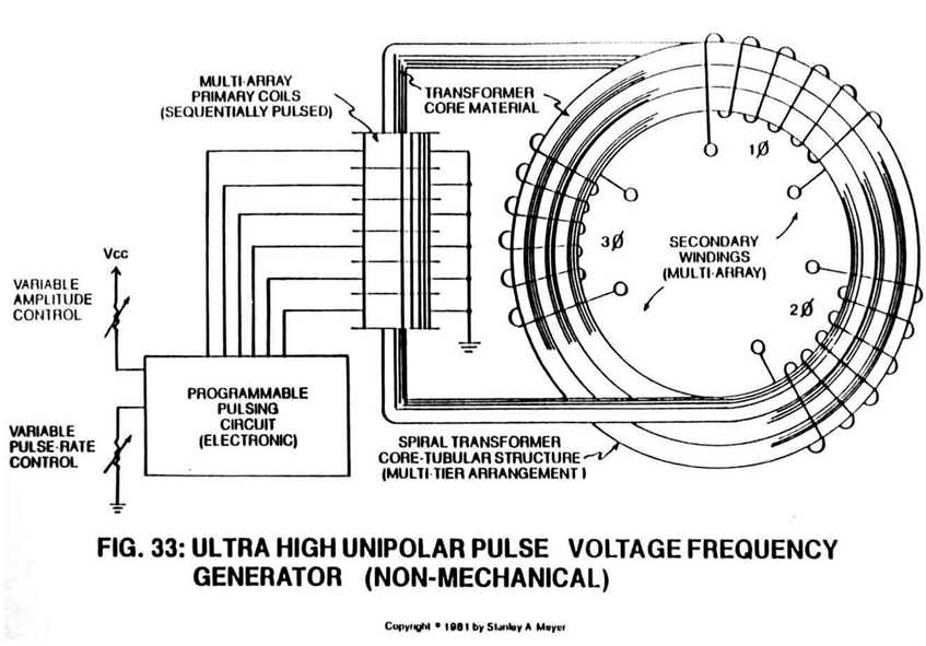
Said tubular pathway (1) can be extended into a spiral configuration (8) of Figure 33.
B) Pickup Coil: Type & Coil Arrangement
Wrap a wire-coil (2) and/or coil-array (2a xxx 2n) around one end of said non-magnetic tube (1) to comply with Maxwell/Faraday Laws of Inductance.
Said pickup coil (2) is placed around said spiral pathway (8) of Figure 33 to form a coil-array (2a xxx 2n).
C) Particle Accelerator Assembly: Purpose & Placement
Insert into and affixed a Particle Accelerator Assembly (10) to said closed loop tube (1) as to (8), locating said Particle Accelerator Assembly on opposite end of tube (1) away from said pickup windings (2 xxx 2n), as shown in Figure 26.
Said Particle Accelerator Assembly (10) causes and propels a permanent magnetic fluid-medium (3 of Figure 26) (liquid slurry or gases) to move toward, through, and beyond said pickup coils (2) for recycling, as illustrated in Figure 26.
Said Particle Accelerator Assembly (10) can take on different design configurations to utilize different energy inputs to overcome different climatic and operational conditions.
A Mechanical Accelerator Drive Assembly (20 of Figure 27) utilizes a non-magnetic turbine wheel (21) to physically move said magnetic fluid-medium (3) inside said tubular pathway (1).
Electromagnetic Pump Assembly (30 of Figure 28 as to Figure 33) moves said fluid-medium (3) by way of electromagnetic deflection, see Figure 26f.
Said mechanical drive system (20) and/or Electromagnetic Pump Assembly (30) can be used separately, joined together, or periodically spaced around said tubular structure (1) as to (8).
D) Energy Input: Mechanical to Electrical Interfacing
Power Train linkage (22) to said non-magnetic turbine wheel (21 of Figure 27 can take different forms:
AC/DC Electric Motor powered by solar or conventional electrical power; Hydraulics; Steam Power; Wind Power; Internal combustion engine, and/or manpower.
Electromagnetic Pump Assembly (30 of Figure 28 as to Figure 33) is energized by a variable AC electrical power source (34).
E) Permanently Magnetized Fluid-Medium: Liquid Slurry to Gas Formation
Fill said closed loop tubular pathway (1) as to (8) with a permanently magnetized material (3), as illustrated in Figures 26, 27, 29, and 30.
Said permanently magnetized material (3) can either be in a liquid slurry and/or gas form.
Said liquid slurry is composed of micro-size permanently magnetized particles suspended in a fluid-medium such as liquid Teflon or light-oil, forming a homogeneous liquid-mass.
Said permanently magnetized gas is composed of atom-size permanently magnetized particles suspended onto an inert carrier gas such as nitrogen argon, forming a homogeneous gas-mass.
Both homogeneous masses can be doped with different permanently magnetized atoms to encourage electromagnetic field enhancement.
Scientific Fact:
The smallest part of a permanent magnet is its atomic structure.
F) Magnetic Field Formation: An Electronic Process
Once said tubular pathway (1) as to (8) is completely filled with said permanently magnetized material (3), said pickup coil-array (2a xxx 2n) is electrically energized to produce an electromagnetic field that completely surrounds said tubular pathway (8) of Figure 33, exposing said magnetic material (3) to said electromagnetic field... causing said material (3) to become permanently magnetized...forming a longitudinal field (4) of Figure 26 emitting from said tubular pathway (1).
Said longitudinal field (4) remains after said coil-array (2a xxx 2n) is de-energized.
 |
|
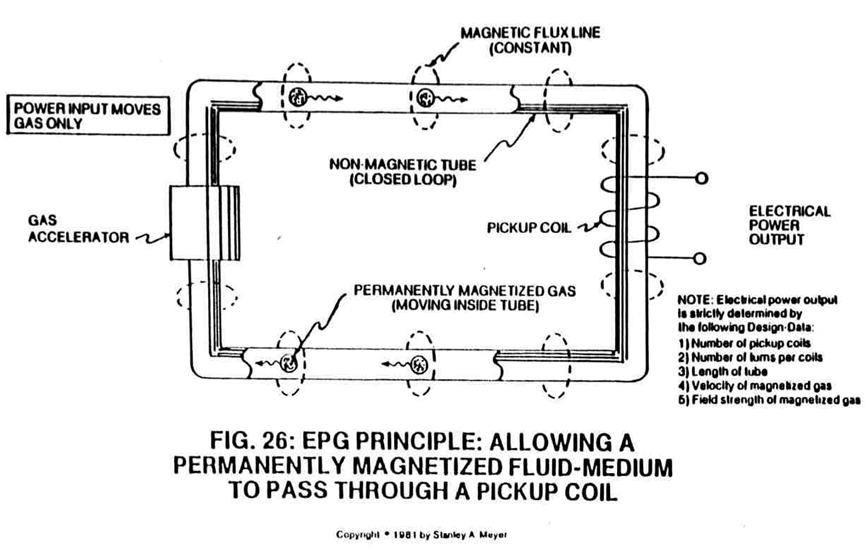
No other energy is needed to maintain said magnetic field (4).
Electronic Fact: At this point, above said magnetizing process duplicates the same function as a Toroidal Pulsing Core in electronic circuit applications. Except said Toroidal core material becomes demagnetized after electrical power is
removed.removed.
G) Magnetic Fields Movement: Linear Spin
Longitudinal movement (moving permanently magnetized fluid-medium inside said tubular pathway) of said magnetic field (4 of Figure 26) is simply accomplished when said Electro/mechanical Pump Assembly (20) of Figure 27 and/or Electromagnetic Pump Assembly (30) of Figure 28 is energized for operability.
By attenuating or varying power input to said power drive systems (20 and/or 30) likewise varies the recycling speed or velocity of said magnetic field (4) moving toward, through, and beyond said pickup coil-array (2a xxx 2n)... moving onward to and through said Power Drive Assembly (20 and/or 30) once again for continued field recycling.
To spin or rotate said magnetic field (4) as to (11 of Figure 26) on its longitudinal axis while moving in a linear direction (4 of Figure 26, 27, and 28) as described above, a Spiral Divider (9) of Figure 26F is now inserted into said tubular pathway (1) leading away from and connecting said Power Drive System (20/30), said Spiral Divider (9) passing through said pickup coil-array (2a xxx 2n), said Spiral Divider (9) terminating at and not passing through said Power Drive System (20/30), as shown in Figure (26F) as to Figures (26, 28, and 33).
The linear-spin movement of said magnetic field (4/11) now duplicates the magnetic field spin of Figure 26ZA without the opposing magnetic field problem (caused by said "Air Gap") associated with standard rotary electrical generators, see "Pre-History to Development" again.
Said Rotary Electrical Generator (Figure 26ZA) simply moved the armature field in one direction; whereas, the EPG System now moves said magnetic field (4/11) in two directions simultaneously: (4) linear direction, (11) axial or spin rotation.
H) Magnetic Field Deflection: Oscillating a permanent magnetic field
To pulsate or vary said rotational field (11) moving in a linear direction (4), Dual-Orientational coils (12/13 of Figure 27) are now inserted into said tubular pathway on opposite side of Electromechanical Drive System (20), away from said pickup coil-array (2a xxx 2n), as illustrated in Figure (27) as to Figure 30.
The dual-pulsing coils (12/13) perform a sequential function:
First, when electrically energized, said dual-coils (12/13) stabilize said magnetic field (4/11) since said turbine wheel (21 of assembly 20) disrupts the electromagnetic field alignment (15a xxx 15n) (electromagnetic attraction force) between said permanently magnetized particles (3a xxx 3n) moving inside non-magnetic tubular pathway (1 as to 8), see Figure 27 as to Figure 30.
Secondly, said moving field (4/11) is terminated when said dual-coil assembly (12/13) is de-energized... allowing said particles (15a xxx 15n) to go into a state of reformation of said magnetic field sequence.
Re-energizing said coils (12/13) causes said particles (3a xxx 3n) to go into alignment once again... reforming magnetic field (4/11).
Pulsing said Orientation-coils (12/13) quickly causes a vertical deflection (17a xxx 17n of Figure 26A) of said magnetic field (4/11).
Pulsing said Orientation-coils slowly causes a horizontal deflection (18a xxx 18n of Figure 26A) of said magnetic field (4/11).
In both cases, said reforming magnetic wave-forms (17a xxx 17n and/or 18a xxx 18n) are oscillating inside said coil-array (2a xxx 2n)... producing electrical
energy. Pulse-frequency electrical output (23 of Figure 30 as to Figure 27) is strictly determined by the pulse-rate of said orientation coils (12/13).
Said Orientation Coil Assembly (12/13) is similar in design and simply creates an electromagnetic field equal to said electromagnetic attraction force (15a xxx 15n). Variable Pulse Voltage Frequency Generator (14 of Figure 27) (Figure 9XB as to Figure 9XAA) is used to trigger or energize said pulsing coils at the same time (12/13) during particle (3) deflection.
--- Transformer interaction (magnetic field coupling) between said Orientation Coils (12/13) and said pickup coils (2a xxx 2n) can "NOT" occur since said particles (3a xxx 3n) are permanently magnetized.
The magnetic pulsing process simply spins the dyne-axis of said particles (3a xxx 3n) to oscillate and attenuate a permanent magnetic field (4/11 as to 17/18), as illustrated in Figure 30 as to Figure 26 through Figure 33. The magnetic pulsing action (17/18) duplicates the magnetic-pulsing action of Figure 26ZA without "the opposing magnetic field problem" (caused by said Air Gap) associated with standard rotary electrical generators, see "Pre-History to Development" once again.
--- A three-directional magnetic waveform is now formed and used during EPG electrical power generation: Spinning (11) said pulsating magnetic field (17/18) in a linear (4) direction... simultaneously. Prior Art simply moves the magnetic field in one direction only, see Figure 26ZA again.
I) Magnetic Field Clustering: Increasing Magnetic Flux Lines
To move more magnetic flux lines through said pickup coil-array (2a xxx 2n) while keeping said particle (3a xxx 3n) velocity constant, said Spiral Divider (9) of Figure 26F is now subdivided into many pathway channels (19a xxx 19n), as illustrated in Figure 26A sub-titled "Rotational Deflection."
The multi-channel spiral divider (19a xxx 19n) is composed of any type of material (such as electrical steel M27) that will "NOT" become permanently magnetized (when exposed to said moving magnetic field (4)) when "shunting" said magnetic field (11a xxx 11n), as shown in Figure 26A sub-titled "Rotational Deflection." Since each spiral channel pathway (19) performs the same function as said pathway (1), many magnetic flow circuits (11a xxx 11n) are formed as to the number of said pathway channels (19a xxx 19n). If more longitudinal magnetic fields (19a xxx 19n) are required... simply increase the number of pathway channels (19).
To increase said magnetic flux lines (11a xxx 11n) still further, said pathway (1) is now spiraled (8 of Figure 33) (in spaced relationship to each other) inside said pickup coil-array (2a xxx 2n), as illustrated in Figure 33 as to cross-sectional drawing titled "Multi-tubular array of...