Resonant Cavity
N) Resonant Cavity:
PURPOSE: To enhance hydrogen gas production beyond voltage attenuation by way of compounding-action (particle impact)
Circuit Stage:
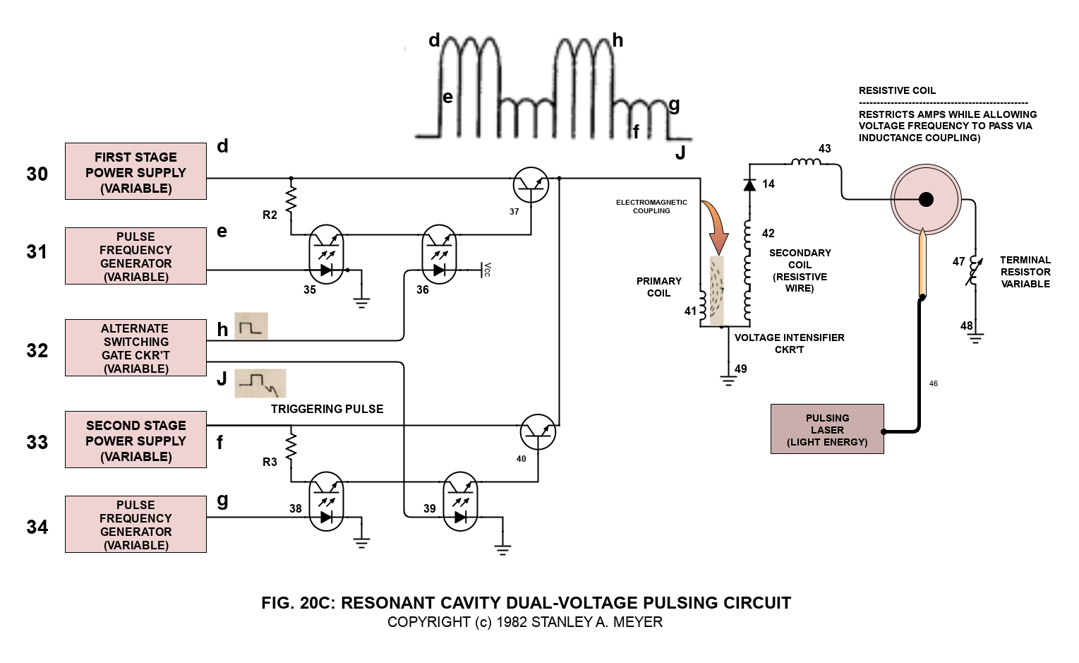
Integrating dual-pulsing circuit (33) (34) (38) (39) (40) to voltage intensifier circuit (Figure 9) previously described), as shown in Figure 20C.
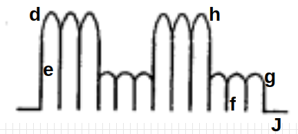
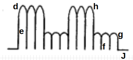
As shown in Figure 20C. variable gate circuit (32) is a two-state switch device which is directly linked to both opto-coupler (36) and opto-coupler (39). As (H) near ground or low state (0 volts), opto-coupler (36) is triggered on. allowing pulse voltage frequency (d) as to (e) to form.
Once said gate circuit (32) changes state (low to high voltage or versa), trigger pulse (J) turns on opto-coupler (39) to form voltage wave form (f) as to (g).
Triggered pulse (H) is now terminated, switching off said wave form (d) (e).
Repeating said alternate gate switching produces dual-voltage pulse-train (51) of Figure (16).
 Wave form (d) (e) and wave form (f) (g) now pulse-duty (52) which is varied from one duty-pulse one hundred duty-pulses (establishing pulse-train 51) via gate circuit (32) (tenth and eleventh steps to voltage attenuation).
The reoccurring duty-pulse (52) is now attenuated to provide maximum gas-yield while minimizing amp flow.
This is accomplished in several ways:
1. Gated pulse (H) as to gated pulse (J) is proportionally changed to "concentrate" or "expand" said applied voltages to said resonant cavity. Said gated pulse train (53, on time) as to (54, off time) is adjustable from 1% to 100% duty time. As on-time (53) increases, off-time (54) proportionally decreases, allowing more voltage pulses (53) to be applied to said resonant cavity (44). To reduce the number of voltage pulses (53), simply reverse the pulse-train adjustment of said gate control circuit (32).
Once the gated pulse-train (51) is set as to maximizing gas production, the gated duty-cycle pulse (52) is now varied from one duty-pulse per second duration (52a) to one hundred duty-pulses per second duration (52n) to help restrict amp flow.
2. Said voltage amplitude (d) is varied to increase gas-yield. After said voltage amplitude (d) is stepped up, applied voltage range to said cavity (44) is from less than one volt to 5,000 volts or more.
3. Said voltage pulse frequency (e) is now varied from 1 Hz to 1 MHz and more, increasing gas-yield still further.
Said voltage amplitude (f) is varied to sustain and compounding-action within said resonant cavity (44). Said voltage amplitude (f) is adjusted as to cavity-size. An increase in voltage amplitude (f) is required as cavity-size increases.
4. Once compounding-action is properly maintained, voltage amplitude (f) is adjusted "no" further to keep amp flow to a minimum (twelfth step to voltage attenuation and eleventh step to amp restriction).
Once step up, voltage range (f) is the same as voltage range (d), one volt to 5,000 volts or more.
Caution: Said voltage amplitude (d) should never be less than said voltage amplitude (f) in order to maintain said compounding action.
5. Said voltage pulse frequency (g) is now adjusted from 1 Hz to 1 MHz or more to reduce amp flow still further while maintaining said compounding-action.
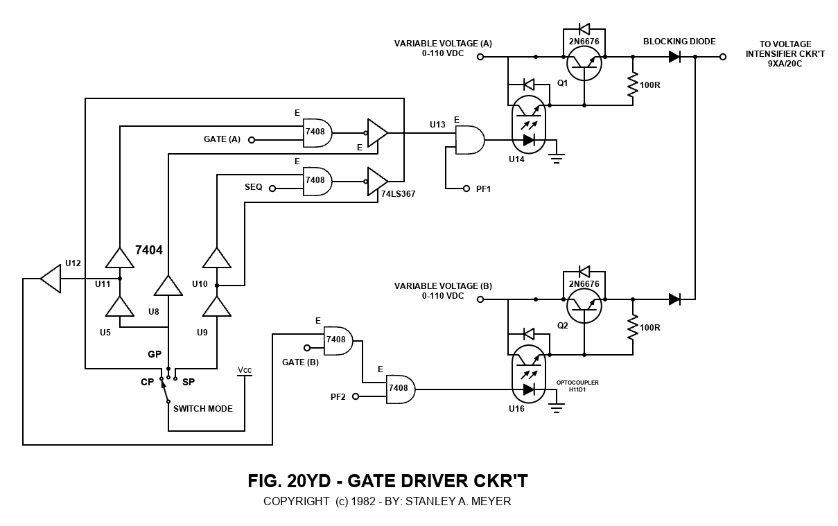
6. Said variable gate circuit (55) of Figure 20D is now retrofitted to said dual-pulsing circuit 20C to extend gas production beyond the limits of a single resonant cavity, keeping power loading to a minimum while adding another gas control feature.
7. As shown in Figure 20D, said resonant cavities are stacked exit port to inlet port to accelerate said compounding-action per stage.
8. Pulse-train (53) and pulse-train (54) can be of different pulse voltage frequency with different voltage amplitude adjustments, each pulse-train performing different functions. Pulse-train (53) regulates gas production on demand; whereas, pulse-train (54) maintains compounding action while restricting amp flow.
9. All above said voltage control features may be used separately, grouped together in sections, or adjusted in a systematic way to control said gas production on demand.


