
Resonant Cavity Mode of Operability
In scientific quantitative analysis (see Exhibit AX, McGraw-Hill Encyclopedia of Science and Technology, Volume 14, Page 489, and Exhibit BX, The Encyclopedia of Chemistry (Hampel/Hawley), Third Edition, Page 585), said water molecule is known to take on polar charges and that gas ionization can take place under certain conditions.
As herein described, said resonant-cavity fuel cell technology (see Water Fuel Cell Technical Brief in reference to Section A through Section M), simply encourages gas ionization (over and beyond prior art) of said water molecule atoms to increase gas-yield beyond said voltage attenuation prior to gas-ignition.
Gas ionization and utilization occurs in the following way:
-
Said water molecule (having polar charges as per Exhibit AX) is subjected to a high-intensity voltage pulse that separates said water molecule atoms by way of opposite polarity attraction law of physics, liberating hydrogen and oxygen gases from water. Ambient air gases dissolved in said water are also being released during said voltage process. Said fuel cell is a multi-gas generator.
-
As said liberated gases are exposed to a pulsating laser or light-emitting source (45), said liberated gases absorb said light radiation, causing many liberated gas atoms to lose electrons, said changed atoms now become positively charged ions. Said electromagnetically primed (atoms absorbed photon energy) hydrogen atom may now accept said liberated electron, forming a negative ion (see Exhibit BX).
-
In both cases, said formed ions are now subject to motion or deflection by said high-intensity voltage pulses (53/54). Compounding action (resonant action) now occurs since said ions' movements are directly related to said voltage pulse frequency. By simply increasing said pulse voltage frequency, said ions' movements increase. By decreasing said pulse voltage frequency, said ions' movements slow down. By keeping said pulse voltage frequency constant, said ions' movements remain constant. By increasing said voltage pulse amplitude, ion movement speeds up.
-
Since said ions are in motion, particle collision is now occurring when said ions' particles strike (physical impact or physical force) said water molecules undergoing said voltage separation, increasing said gas yield.
-
Particle collision also causes other liberated atoms to become ionized beyond the absorption of said light radiation, liberating more electrons inside said resonant cavity (44).
-
Since said liberated electrons have a negative electrical charge, said positive voltage pulse now causes said electrons to be moved uniformly with said pulse voltage frequency, aiding said compounding action (resonant action) still further.
-
To increase gas yield still further, said ionized or charged particles of gases are now injected into other resonant cavities undergoing above said resonant action process (see Figure 20D as to Figure 20C).
Geometrical gas production (Figures 13, 14, and 15) occurs when said resonant cavities are stacked exit port to inlet port or as a singular cavity unit. Said geometrical gas rate peaks out (or stops) when water flow rate into said resonant cavity becomes constant or reduced during gas production.
8. To increase and encourage greater particle collision (particle impact), accelerator tube (56) of Figure (20A) is placed between said resonant cavity stages (see Figure 20 and 20D).
 Said expelled charged gases (movement of gases between cavity units) move toward, through, and beyond oppositely electrically charged plates or voltage zones (57 of Figure 20A) which are periodically spaced inside said transfer tube (56).
By repeating said gas attraction process (20A) many times, said charged gas particles increase in velocity since sequential gate circuit (58) applies greater voltage potential per gas attraction stage (57).
Increasing particle velocity directly increases gas yield to the next resonant cavity stage. Adding more accelerator tubes (56a through 56n of Figure 20B) per resonant cavity stage (see Figure 20) increases gas yield still further (see Figure 20B again).
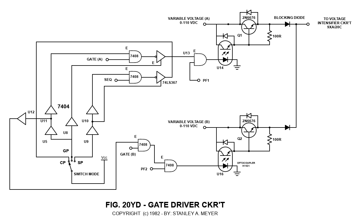 Varying gate switch circuit (58) is another way to control gas production on demand (fourteenth step to voltage attenuation).
Sequentially switching off and on accelerator tube array (56a through 56n) (parallel or series hookup) is another way to control gas production on demand (fifteenth step to voltage attenuation).
Figure 20A - Gas Accelerator Tube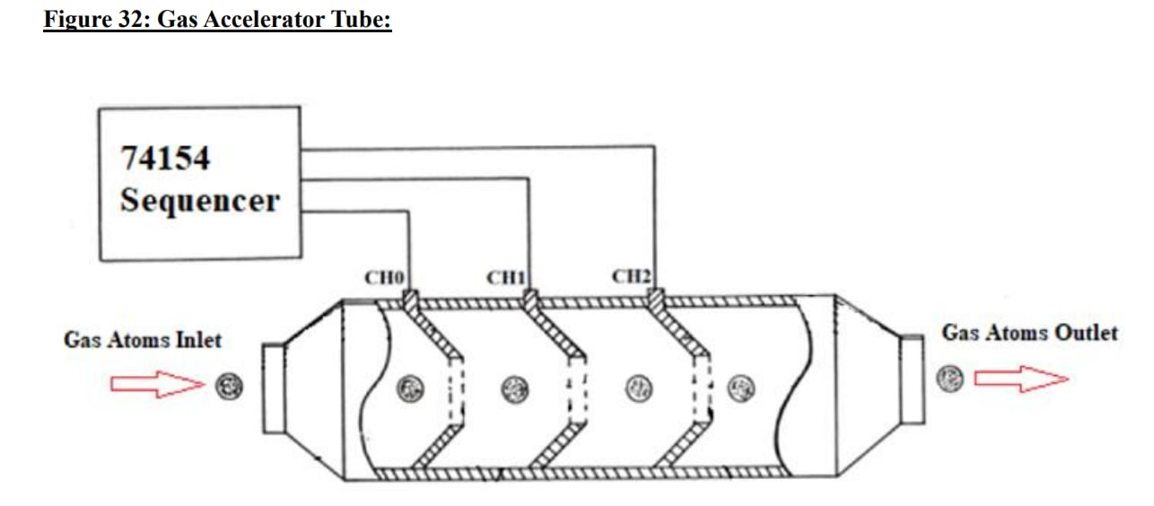
9. To prevent electrical discharge of said particles of gas when said resonant cavity (44) and said gas attraction zones (57) are submerged in natural water, said fuel cell housing is composed of an electrical insulating material such as plastic or spun glass.
Electrical positive and negative terminal surfaces are coated with an insulating material as shown in Figure 9D.
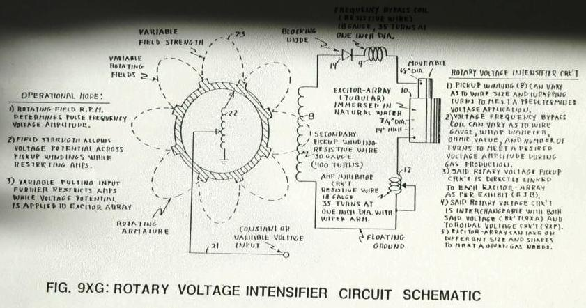
10. Said voltage intensifier circuit of Figure 9 as to Figure 9XA, Figure 9XF, and Figure 9XG are the same as Figure 20C, toroidal voltage intensifier circuit of Figure 20YG, and rotary voltage intensifier circuit of Figure 20YH, performing the same amp restricting/voltage attenuation functions as herein described.
The resonant cavity fuel cell can produce more than 115-cc/min of gases at one amp leakage.