Analog Voltage generator (40)
20 December 2023
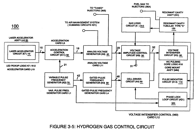
The generated digital signal (19) being electrically transmitted from accelerated control circuit (30) of Figure (3-5) is, now, electronically detected, translated, and converted into a analog voltage signal (22) which is continuously proportionate to input signal (19) by Analog Voltage Generator Circuit (40) of Figure (3-5).
The newly formed analog signal (22) of Figure (3-14) is a voltage level signal that varies continuously in both time and amplitude to produce a voltage level which is directly proportional to the physical change in pulse train (100 xxx 16n) of Figure (3-13).
|
Figure (3-13)
|
Figure (3-14)
|
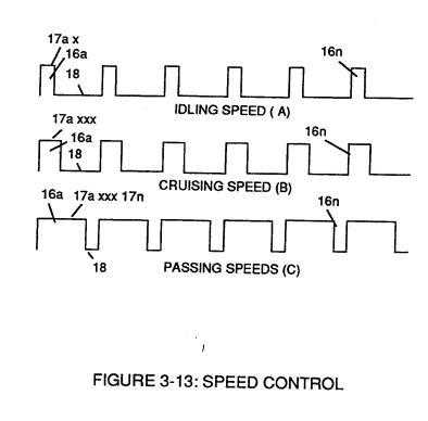
As pulse width (17ax) of signal (19) changes so does analog voltage level output (23) of Figure (3-14).
Widening pulse width to stop-position (17a xxxx 17n) of Figure (3-13) causes analog signal (22) to increase to higher voltages levels; whereas, analog voltage level (22) drops (become lower in value) in voltage level when pulse width decreases to start-position (17a).
The resultant and varied voltage level (22a xx) varies smoothly over a continuous range of voltage valves (22a xxx 22n) rather than in discrete steps, as illustrated in linear graph (23) of Figure (3-14).
In terms of functional-ability and purpose, analog circuit (40) of Figure (3-5) provides a variable (controlled) voltage output (23) in direct relationship to light gate (9) displacement which, in turns, sets up and controls Resonant Action (160) of Figure (3-23) that produces Fuel Gases on demand.
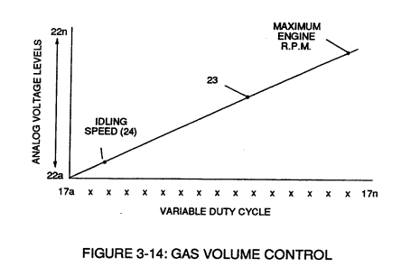 Analog circuit (40) also calibrates both engine idling speed (22ax) and maximum engine R.P.M. (22a xxx 22n) by adjusting and maintaining a predetermined or given low (24) and high voltage levels respectively, as further illustrated in Figure (3-14).
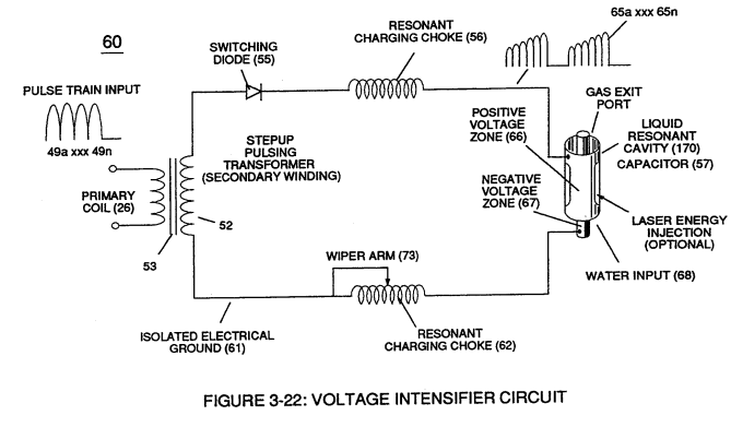
Voltage valves or levels (22a xxx 22n) simply controls the applied voltage potential across Resonant Cavity Assembly (120) of Figure (3-22) through voltage amplitude control circuit (50) of Figure (3-5) which is is electrically linked to primary coil (26) of Figure (3-22) of Voltage Intensifier Circuit (60) of Figure (3-5).
|
Figure (3-22)
|
Figure (3-5)
|