(60)
Voltage Intensifier Circuit
Also written electrical circuit · circuit · pulsing circuit
Where it is first named
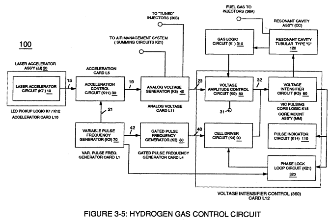
Voltage valves or levels (22a xxx 22n) simply controls the applied voltage potential across Resonant Cavity Assembly (120) of Figure (3-22) through voltage amplitude control circuit (50) of Figure (3-5) which is is electrically linked to primary coil (26) of Figure (3-22) of Voltage Intensifier Circuit (60) of Figure (3-5).
How it is written
- (60) 30×
Drawings 76
-
Figure (3-5) · Acceleration Control Circuit (30)
-
Analog Voltage Circuit (40), as shown in Figure (3-5) · Acceleration Control Circuit (30)
-
Figure (3-5) · Acceleration Control Circuit (30)
-
Figure (3-5) · Analog Voltage generator (40)
-
Figure (3-22) · Voltage Amplitude Control Circuit (50)
-
Figure (3-22) · Voltage Intensifier Circuit (60)
-
Voltage Intensifier Circuit (60) of Figure (3-22) · Gas Processor
-
Figure (3-5) · Laser Distributor
-
Figure (3-46) · Steam Resonator
-
Carries this number · WFC 422DA - Illustrations
-
Carries this number · WFC 422DA - Illustrations
-
Carries this number · WFC 422DA - Illustrations
-
3-4 Inner Core Bobbin · Voltage Intensifier Coil Assembly
-
3-8 Multi-Coil Spool · Voltage Intensifier Coil Assembly
-
Carries this number · Electronic Circuit Design
-
Carries this number · Water Fuel Injector (Taper Resonant Cavity Chamber)
-
(520) of Figure (4-3) · Funneling Effect
-
2-3 Water Inlet Housing · Water Fuel Injector Illustrations
-
Carries this number · Steam Resonator Assembly
-
Carries this number · Steam Resonator Assembly
-
Figure (4-4) · Water Fuel Injection System - Page 1
-
Carries this number · Energy Pumping Action
-
(520) in Figure (5-3) · Resonant Propagation
-
(520) of Figure (5-3) · In Application of Usage
-
(520) of Figure (5-3) · Solar Energy Actuator
-
Carries this number · Illustrations
-
Hydrogen Fracturing Process (520) of Figure (5-3) · Voltage Intensifier Coil-Assembly
-
Voltage Intensifier Circuit (60) of Figure (3-22) · Instant Explosion of Water
-
(56/62) of Figure (3-22) · Instant Explosion of Water
-
(56) of Figure (3-22) · Instant Explosion of Water
-
Carries this number · Inductance (FL)
-
(650) of Figure (7-4) · Inductance (FL)
-
Carries this number · 8-2 - Traveling Voltage Wave-Guides
-
(520) of Figure (5-3) · 8-2 - Traveling Voltage Wave-Guides
-
(650) of Figure (7-4) · 8-4 - State Space (Sp)
-
Energy Pumping Action (520) of Figure (5-3) · WFC Development Objectives
-
Carries this number · WFC Development Objectives
-
Voltage Intensifier Circuit (60) of Figure (3-22) · Propagating Electrical Stress
-
Carries this number · Propagating Electrical Stress
-
(60) of Figure (3-22) · Propagating Electrical Stress
-
bipolar electrically charged water molecule (210) of Figure (3-46) · Voltage Flexing Process
-
Figure (3-22) · Analog Voltage generator (40)
-
Figure (3-21) · Voltage Amplitude Control Circuit (50)
-
Figure (3-26) · Voltage Intensifier Circuit (60)
-
Figure (3-21) · Voltage Intensifier Circuit (60)
-
The figure it sits on · Voltage Dynamics
-
Figure (3-22) · Voltage Dynamics
-
In both cases, electrical charge deflection or movement is directly related to applied voltage (65). · Voltage Dynamics
-
Ions or particle mass having the same or like electrical charges will move away from one another, as illustrated in (220) of Figure (3-29). · Voltage Dynamics
-
Figure (3-29) · Electrically Charged Water Molecule
-
Figure (3-26) · Electrically Charged Water Molecule
-
The figure it sits on · Gas Processor
-
(270) of Figure (3-34) · Gas Processor
-
The figure it sits on · WFC 422DA - Illustrations
-
The figure it sits on · WFC 422DA - Illustrations
-
The figure it sits on · WFC 422DA - Illustrations
-
The figure it sits on · WFC 422DA - Illustrations
-
3-5 Outer Core Bobbin · Voltage Intensifier Coil Assembly
-
The figure it sits on · Differential Air-Gas Inlet Control
-
Figure (25) · Water Fuel Injector (Taper Resonant Cavity Chamber)
-
(160) of Figure (3-26) · Water Fuel Injection System - Page 1
-
Figure (5-5) · Resonant Propagation
-
(85) of Figure (3-26) · In Application of Usage
-
(160) of Figure (3-26) · In Application of Usage
-
(270) of (3-34) · In Application of Usage
-
The figure it sits on · Illustrations
-
(85) of Figure (3-26) · Resistance (Rs)
-
(90) of Figure (5-5) · Capacitance Reactance
-
Voltage Dynamics (220) of Figure (3-29) · Electron Bounce Phenomenon
-
... causing "electron clustering" (641a xxx 641n) to take place within Copper Wire Zone (52) during pulse on- time (T1) · Electron Bounce Phenomenon
-
(90) of Figure (5-5) · 8-2 - Traveling Voltage Wave-Guides
-
The figure it sits on · WFC Exhaust Air Reclaimer
-
Voltage Dynamics (220) of Figure (3-29) · WFC Exhaust Air Reclaimer
-
Figure (3-34) · Propagating Electrical Stress
-
(160) of Figure (3-26) · Propagating Electrical Stress
-
blocking diode (55) of Figure (3-34) · Voltage to Amp Differential Ratio
Where it is named · 30
Analog Voltage generator (40) 1×
-
Voltage Intensifier Circuit (60)
Voltage valves or levels (22a xxx 22n) simply controls the applied voltage potential across Resonant Cavity Assembly (120) of Figure (3-22) through voltage amplitude control circuit (50) of Figure (3-5) which is is electrically linked to primary coil (26) of Figure (3-22) of Voltage Intensifier Circuit (60) of Figure (3-5).
Voltage Amplitude Control Circuit (50) 2×
-
Voltage Intensifier Circuit (60)
Variable voltage range (32a xxx 32n) from one (1) up to twelve (12) volts (regulating battery voltage) is applied across primary coil (26) of Voltage Intensifier Circuit (60) of Figure (3-21).
-
Voltage Intensifier Circuit (60)
In terms of operability, Laser Accelerator Assembly (20) of Figure (3-5) is, now, attenuating battery voltage potential (32a xxx 32n) which is electrically connected to Voltage Intensifier Circuit (60) of Figure (3-5).
Voltage Intensifier Circuit (60) 8×
-
Voltage Intensifier Circuit (60)
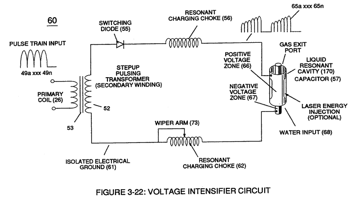
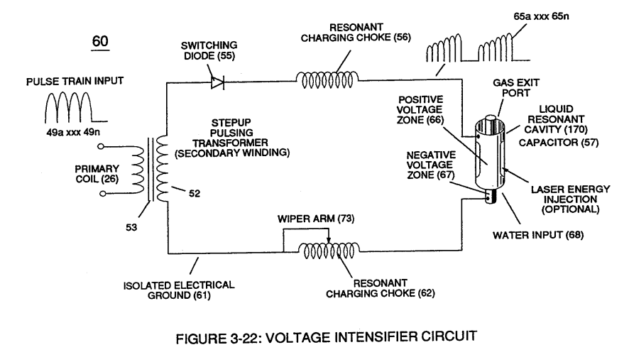
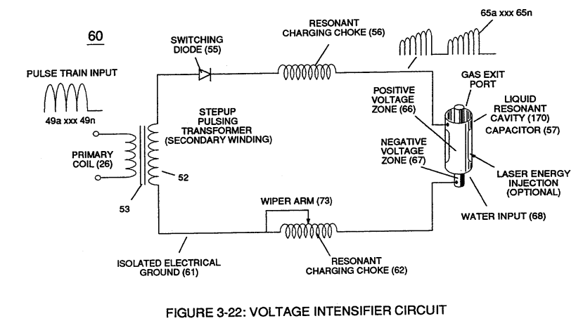
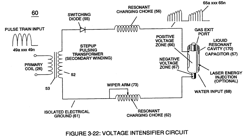
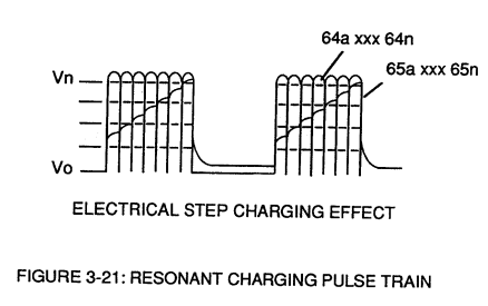
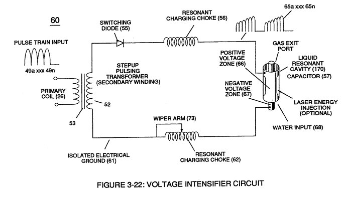
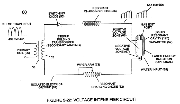
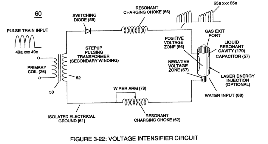
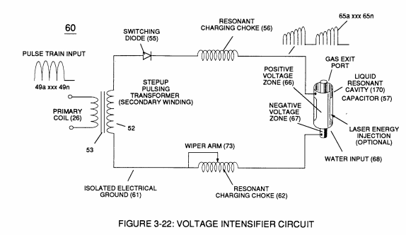
The resultant signal coupling ( 65a xx 65n ) of Figure (3-21) is accomplished since primary coil (26), pulsing core (53), secondary coil (52), switching diode (55), resonant charging choke (56), resonant cavity assembly (170), natural water (68), and variable resonant charging choke (62) forms Voltage Intensifier Circuit (60) of Figure (3-22), as illustrated in Figure (3-22) as to Figure (3-23).
-
electrical circuit (60)
but, also, and at the same time functions as an electronic switch which opens electrical circuit (60) during pulse off-time
-
circuit (60)
"Voltage intensity or level across excitor array (57) can exceed 20,000 volts due to circuit (60) interaction and is directly related to pulse train (64a xxx 64n) variable amplitude input.
Voltage Dynamics 5×
-
electrical circuit (60)
Voltage is "electrical pressure" or "electrical force" within electrical circuit (60) and is known as voltage potential (65a xxx 65n) of Figure (3-21).
-
electrical circuit (60)
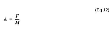
The higher the voltage potential (Vo xxx Vn), the greater "electrical attraction force" (qq') or "electrical repelling force" (ww') of Figure (3-29) is applied to electrical circuit (60) of Figure (3-22).
-
electrical circuit (60)
Unlike voltage charges within electrical circuit (60) steps up "electrical attraction force" (qq'); whereas, like electrical charges within the same electrical circuit (60) encourages an "repelling action" (ww'), as illustrated in Figure (3-29).
-
electrical circuit (60)
Unlike voltage charges within electrical circuit (60) steps up "electrical attraction force" (qq'); whereas, like electrical charges within the same electrical circuit (60) encourages an "repelling action" (ww'), as illustrated in Figure (3-29).
-
electrical circuit (60)
Likewise, Ions or charged particles (atoms having missing or sharing electrons between unlike atoms) within electrical circuit (60) having unlike electrical charges are attracted to each other.
Electrically Charged Water Molecule 1×
-
circuit (60)
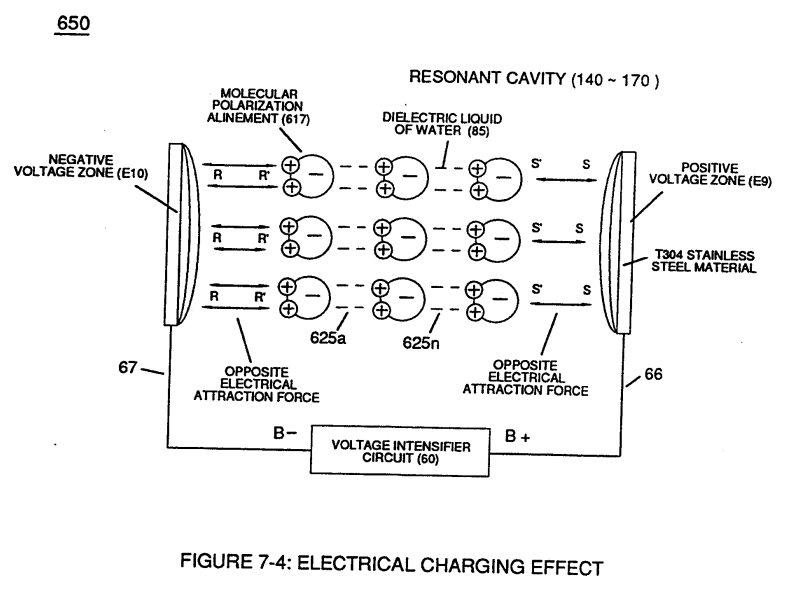
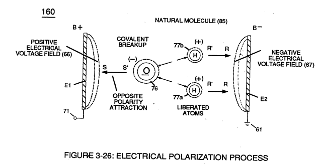
Voltage potential (65) within electrical circuit (60) can cause one or more electrons (79) to be dislodged from the water molecule atom (85) of Figure (3-26) due to opposite electrical polarity attraction (qq') of Figure (3-29) between unlike charged entities, as shown in (160) of Figure (326) as to Newton's and Coulomb's laws of electrical-force.
Gas Processor 3×
-
Voltage Intensifier Circuit (60)
The resultant ionized gas process (260) of Figure (3-33) is performed by Electron Extraction Circuit (270) of Figure (3-34) which function in like manner to Voltage Intensifier Circuit (60) of Figure (3-22) except amp consuming device (390) (such as a light bulb 11_2) placed between Resonant Charging Choke (56) and Gas Resonant Cavity (410) of Figure (3-34) is added to pulsing circuit ( …
-
pulsing circuit (60)
… ) of Figure (3-22) except amp consuming device (390) (such as a light bulb 11_2) placed between Resonant Charging Choke (56) and Gas Resonant Cavity (410) of Figure (3-34) is added to pulsing circuit (60) to cause and convert liberated electrons (117a xxx 117n) into radiant heat - energy (Kinetic energy) (113) in the form of light energy (114)
-
Voltage Intensifier Circuit (60)
Voltage Intensifier Circuit (60) of Figure (3-22)
Resonant Propagation 2×
-
(60) of Figure (5 -3)
Water Fuel Injector 1×
-
… r enhanced by simply electrically interfacing voltage intensifier (VIC) circuit coil-assembly (580) of Figure (6-1) with 'Taper Resonant Cavity" (590) of Figure (6-2), as schematically illustrated in (60) of Figure (3-22) as to pulse core configuration (190) of Figure (3-23) (Memo WFC 422 DA) titled "WFC Hydrogen Gas Management System.
Instant Explosion of Water 3×
-
Voltage Intensifier Circuit (60)
Voltage Intensifier Circuit (60) of Figure (3-22) (Memo WFC 422 DA) as to Figure (1-1) (Memo WFC 420) and Voltage Intensifier Circuit (620) of Figure (7-1) are specifically designed to restrict amp flow during Programmable Pulsing Operations (49a xxx 49n) but in different operational modes:
-
Voltage Intensifier Circuit (60)
Voltage Intensifier Circuit (60) of Figure (3-22)
Propagating Electrical Stress 4×
-
Voltage Intensifier Circuit (60)
Beyond amp restricting characteristic of said Amp Inhibiting Circuit (970) of Figure (10-1) as to Voltage Intensifier Circuit (60) of Figure (3-22), the spiral-wrapped coils (Resonant Charging Chokes 56/62) being paired together, also, causes voltage level enhancement beyond applied voltage input since the "Distributed Capacitan …
-
Voltage Intensifier Circuit (60)
Voltage Intensifier Circuit (60) of Figure (3-22)
-
(60) of Figure (3-22)