(32) · also written as a run, 32a xxx 32n
Analog voltage signal
Also written analog voltage signal · nozzle-port · gas exit port · Exit Port · variable voltage amplitude control signal · battery electrical voltage potential · predetermined voltage level · battery voltage potential and 3 more
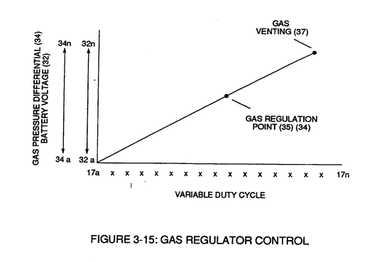
The variable voltage amplitude control signal of Figure 3-15. It sets how high the pulse train (51a xxx 51n) rises, between one and twelve volts, and is joined with the switch-gate (49a xxx 49n) of Figure 3-18 across the primary coil (26) to give the voltage intensifier circuit both its gating and its level. The text once misprints it as (318 xxx 32n); the catalogue reads that as this run.
How it is written
- (32) 16×
- (32a xxx 32n) 4×
- (318 xxx 32n) 1×
- (32a xxx) 1×
32a xxx 32n is Meyer's shorthand for a run of the same thing: 32a is the first, 32n the last, and the x's stand for however many lie between. Every stage of the run is this one numeral.
Drawings 63
-
Figure (3-15) · Voltage Amplitude Control Circuit (50)
-
Figure (3-23) · Voltage Intensifier Circuit (60)
-
Figure (3-23) · Voltage Dynamics
-
reciprocating WFC Fuel-kits can be similar to Car design (340); · Aviation Application
-
Carries this number · WFC 422DA - Illustrations
-
Carries this number · WFC 422DA - Illustrations
-
Carries this number · WFC 422DA - Illustrations
-
Carries this number · Water Fuel Injection System
-
3-5 Outer Core Bobbin · Voltage Intensifier Coil Assembly
-
Carries this number · Voltage Intensifier Coil Assembly
-
Carries this number · Voltage Intensifier Coil Assembly
-
3-16 Mount Bar · Voltage Intensifier Coil Assembly
-
Carries this number · Electronic Circuit Design
-
Carries this number · Differential Air-Gas Inlet Control
-
Carries this number · Differential Air-Gas Inlet Control
-
Carries this number · Differential Air-Gas Inlet Control
-
(70) of Figure (3B) · Water Fuel Injector (Taper Resonant Cavity Chamber)
-
thereby, attenuating voltage amplitude (voltage intensity) beyond Secondary Coil (53) voltage levels (71), as illustrated in (220) of Figure (18). · Funneling Effect
-
Carries this number · Steam Resonator Assembly
-
Carries this number · Steam Resonator Assembly
-
Carries this number · Steam Resonator Assembly
-
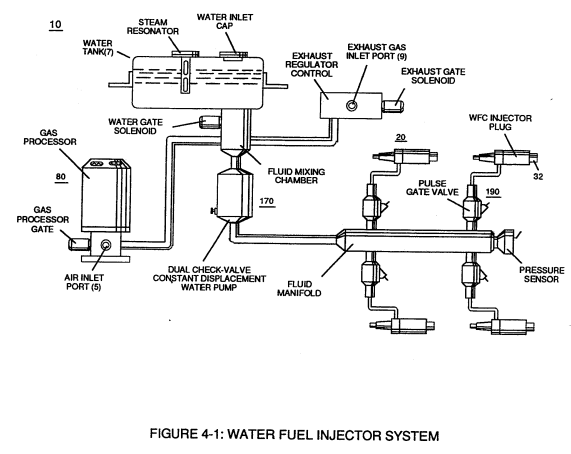
Figure (4-1) · Water Fuel Injection System - Page 1
-
(230) of Figure (3-30) · In Application of Usage
-
(57) of Figure (6-2) · In Application of Usage
-
(Eq 32) hv /c · Solar Energy Actuator
-
Activation Process (590) of Figure (6-2) · Voltage Intensifier Coil-Assembly
-
(190) of Figure (3-23) · Tri - Coil Construction
-
(590) of Figure (6-2) · Capacitance (Cd)
-
Inductance Pulsing-Core (190) of Figure (3-23) · Inductance Reactance (Rs - Cd - FL)
-
Carries this number · Electron Bounce Phenomenon
-
(E9/10) of Figure (6-2) · Voltage Amplitude Switch-Off
-
Carries this number · WFC 427 Illustrations
-
"FullSystem" development (10) of Figure (4-1) · WFC Development Objectives
-
The figure it sits on · Laser Accelerator Assembly
-
Figure (3-5) · Acceleration Control Circuit (30)
-
Analog Voltage Circuit (40), as shown in Figure (3-5) · Acceleration Control Circuit (30)
-
Figure (3-5) · Acceleration Control Circuit (30)
-
Figure (3-5) · Analog Voltage generator (40)
-
Figure (3-21) · Voltage Amplitude Control Circuit (50)
-
Figure (3-1) · Voltage Amplitude Control Circuit (50)
-
Figure (3-21) · Voltage Intensifier Circuit (60)
-
The figure it sits on · Voltage Dynamics
-
To further prevent voltage fluctuation during resonant action, Phase Lock Loop technique of Pulse Indicator circuit (110) is utilized during pulsing operations. · Resonant Action
-
The figure it sits on · Gas Processor
-
Figure (3-1) · Laser Distributor
-
Figure (3-5) · Laser Distributor
-
Hydrogen Fuel-Gas Assembly (450) of Figure (3-1) · Operational Parameters
-
The figure it sits on · WFC 422DA - Illustrations
-
The figure it sits on · WFC 422DA - Illustrations
-
The figure it sits on · WFC 422DA - Illustrations
-
The figure it sits on · WFC 422DA - Illustrations
-
3-15 VIC Mount Plate · Voltage Intensifier Coil Assembly
-
The figure it sits on · Electronic Circuit Design
-
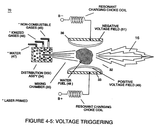
Figure (4-5) · Water Fuel Injection System - Page 1
-
but, also prevents electron flow into destabilizing gas process (180), as so illustrated in Figure (4-5). · Water Fuel Injection System - Page 3
-
The figure it sits on · In Application of Usage
-
Voltage Triggering Process (70) of Figure (4-5) · Voltage Intensifier Coil-Assembly
-
(16) of Figure (4-5) · Resistance (Rs)
-
(370) of Figure (3-40) · Taper Resonant Capacitor (ERt)
-
Quenching Circuit (370) of Figure (3-40) · Capacitance Reactance
-
Figure (4-5) · Capacitance Reactance
-
Figure (4-5) · 8-5 - Energy Vectoring (Ev)
-
The figure it sits on · WFC 427 Illustrations
Where it is named · 22
Voltage Amplitude Control Circuit (50) 10×
-
analog voltage signal (32)
Regulator stage (27) of circuit (50) converts battery voltage potential (29) of Figure (3-6) via electrical terminal (31) of Figure (3-5) as to Figure (3-6) into a analog voltage signal (32) of Figure (3-15) which corresponds to but is electrically isolated (crossover voltage from two separate power supplies) from incoming gas volume signal (23) of Figure (3-14), as shown in Figure (35).
Voltage Intensifier Circuit (60) 2×
-
variable voltage amplitude control signal (318 xxx 32n)
By integrating and joining together variable voltage amplitude control signal (318 xxx 32n) of Figure (3-15) with variable controlled switch-gate (49a xxx 49n) of Figure (3-18) across primary coil (26) of Figure (3-22),
-
Analog voltage signal (32a xxx 32n)
Analog voltage signal (32a xxx 32n) of Figure (3-15) allows pulse train (51a xxx 51n) voltage amplitude (V0 xxx Vn) of Figure (3-19) to vary from one up to twelve volts (battery supply 28 of Figure 3-6 by attenuating Laser Accelerator circuit (10) of Figure (3-5) via Hydrogen Gas Control Circuit (100).
Water Fuel Injection System 3×
-
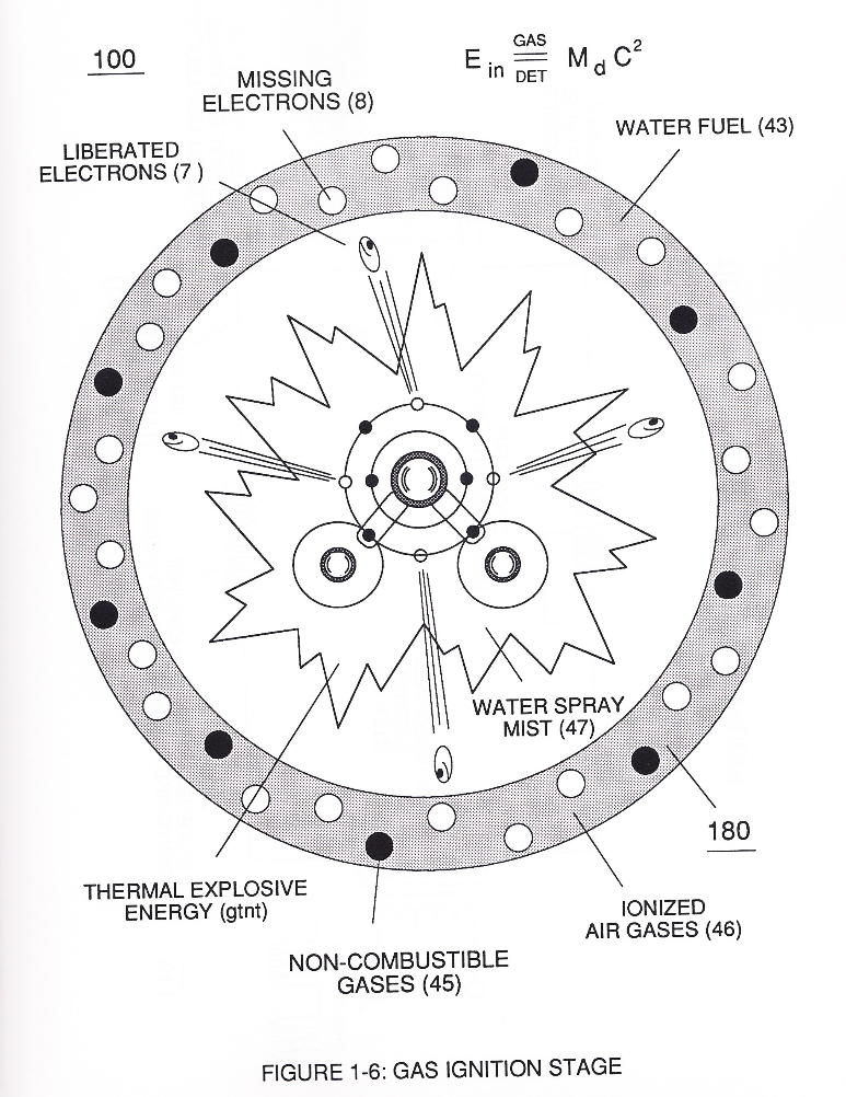
To elevate Energy-flame-temperature still further, help increase fluid-displacement (46/47) while maintaining or reducing the volume flow rate of non-combustible gases (45) during an increase of applied voltage amplitude (Vo x Vn) of Figure (32) as to Voltage Intensifier Circuit (110) of Figure (7) and Electron Extraction Circuit (120) of Figure (8).
-
nozzle-port (32)
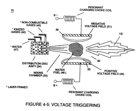
The resultant energy-flame pattern is further maintained by allowing the ignited,compressed, and moving gases (29) of Figure (3B) to be projected to, pass through and beyond nozzle-port (32) under pressure due to gas expansion caused by thermal gas ignition.
Water Fuel Injection System - Page 1 1×
Water Fuel Injection System - Page 2 1×
Water Fuel Injector 1×
-
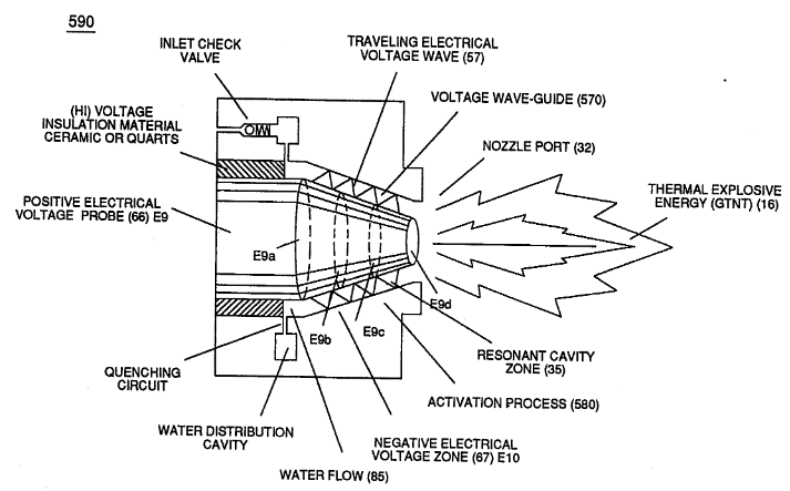
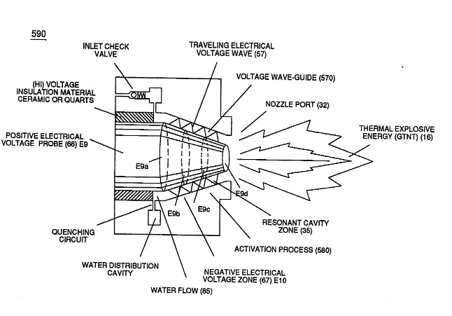
Together, parallel sides (E9 / El0) not only functions as a "voltage wave-guide" (570) but, also, acts and performs as a "voltage intensifier circuit" when applied gated pulse-frequency (64a xxx 64n) travels the length of conical cavity (570) toward exit port (32).
Taper Water Fuel Injectors 1×
-
Voltage wave-guide (570) allows the activation points (E9a xxx E9n) to transpire since wave-guide (570), now, functions as a Quenching Circuit (370) of Figure (3-40) to prevent gas ignition until the traveling gases (under static pressure) are exited out of and away from exit port (32) of Figure (6- 2)
Capacitance Reactance 1×
-
gas exit port (32)
which, when occurring at gas exit port (32) of Figure (4-5), spark-ignites expanding water gas-fuel (45/46/47) of Figure (4-5) during water inject cycle (70) of Figure (4-5)
Voltage Amplitude Switch-Off 1×
-
Exit Port (32)
Voltage levels of variance (Va xxx Vn) is achieved by simply switching-in or switching-out the member of Secondary Coil-cavities (505a xx 505n) (see 740 of Figure 7-13) in direct relationship to Taper Resonant Voltage surfaces (E9/10) of Figure (6-2) which acts and performs as a "Voltage Amplifier" when Compressional Wave-form (B) of Figure (7-12) is intensified at Exit Port (32) of Figure (6-2).
8-5 - Energy Vectoring (Ev) 1×
-
The "mode of operability" of determining the "Operational Parameters" of adjusting the thermal explosive energy (gtnt) exiting from nozzle-port (32) of Figure (4-5) as to (40) of Figure (4-2) is directly related to the characteristics of the applied Voltage Pulse Potential (Vpp) Wave-form (s) (Vpwt) and the geometrical configuration of Resonant Cavity (90) of Figure (4-7) as to (730) of Figure (7-12).