(51) · also written as a run, 51a xxx 51n
Variable amplitude pulse-train
Also written electrical-static spark ignition · variable amplitude pulse-train · venturi tube-cavity · pulse train
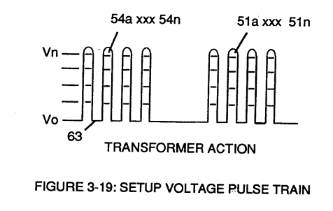
The pulse train as it stands across the primary coil (26), coupled by transformer action through the pulsing core (53) to the secondary coil (52), Figure 3-22. Its amplitude (Vo xxx Vn), Figure 3-19, is varied from one volt up to the twelve of the battery supply (28) by the analog voltage signal (32a xxx 32n), which is how the hydrogen gas control circuit (100) throttles the laser accelerator circuit (10).
How it is written
- (49/51) 3× with (49) Pulse-train
- (51a xxx 51n) 2×
- (49 / 51) 1× with (49) Pulse-train
- (51) 1×
51a xxx 51n is Meyer's shorthand for a run of the same thing: 51a is the first, 51n the last, and the x's stand for however many lie between. Every stage of the run is this one numeral.
Drawings 27
-
Figure (3-19) · Cell Driver Circuit (90)
-
Figure (3-19) · Voltage Intensifier Circuit (60)
-
Figure (3-23) · Voltage Dynamics
-
Carries this number · WFC 422DA - Illustrations
-
(170) of Figure (13) · Water Fuel Injector (Taper Resonant Cavity Chamber)
-
(170) of Figure (13) · Water Fuel Injector (Taper Resonant Cavity Chamber)
-
Fluid Displacement Pump (170) of Figure (13) · Water Fuel Injector (Taper Resonant Cavity Chamber)
-
(70) of Figure (3B) · Water Fuel Injector (Taper Resonant Cavity Chamber)
-
Electronic Circuit (110) of Figure (7) · Water Fuel Injector (Taper Resonant Cavity Chamber)
-
Figure (4-5) · Water Fuel Injection System - Page 1
-
Figure (4-9) · Water Fuel Injection System - Page 2
-
but, also prevents electron flow into destabilizing gas process (180), as so illustrated in Figure (4-5). · Water Fuel Injection System - Page 3
-
Carries this number · In Application of Usage
-
(110) of Figure (4-9) · In Application of Usage
-
Voltage Triggering Process (70) of Figure (4-5) · Voltage Intensifier Coil-Assembly
-
coil-structures (580) of Figure (6-1) · Voltage Intensifier Coil-Assembly
-
(16) of Figure (4-5) · Resistance (Rs)
-
(110) of Figure (4-9) · Resistance (Rs)
-
(580) of Figure (6-1) · Inductance (FL)
-
Figure (4-5) · Capacitance Reactance
-
Figure (4-5) · 8-5 - Energy Vectoring (Ev)
-
Voltage Intensifier Circuit (110) of Figure (4-9) · WFC Exhaust Air Reclaimer
-
Blocking Diode (52) of Figure (4-9) · Propagating Electrical Stress
-
(580) of Figure (6-1) · Voltage to Amp Differential Ratio
-
The figure it sits on · Electronic Circuit Design
-
The figure it sits on · 8-1 - Propagating "Resonant Action" By Voltage Tickling of State Space
-
The figure it sits on · WFC 427 Illustrations
Where it is named · 7
Voltage Intensifier Circuit (60) 2×
-
pulse train (51a xxx 51n)
Analog voltage signal (32a xxx 32n) of Figure (3-15) allows pulse train (51a xxx 51n) voltage amplitude (V0 xxx Vn) of Figure (3-19) to vary from one up to twelve volts (battery supply 28 of Figure 3-6 by attenuating Laser Accelerator circuit (10) of Figure (3-5) via Hydrogen Gas Control Circuit (100).
Water Fuel Injection System 1×
-
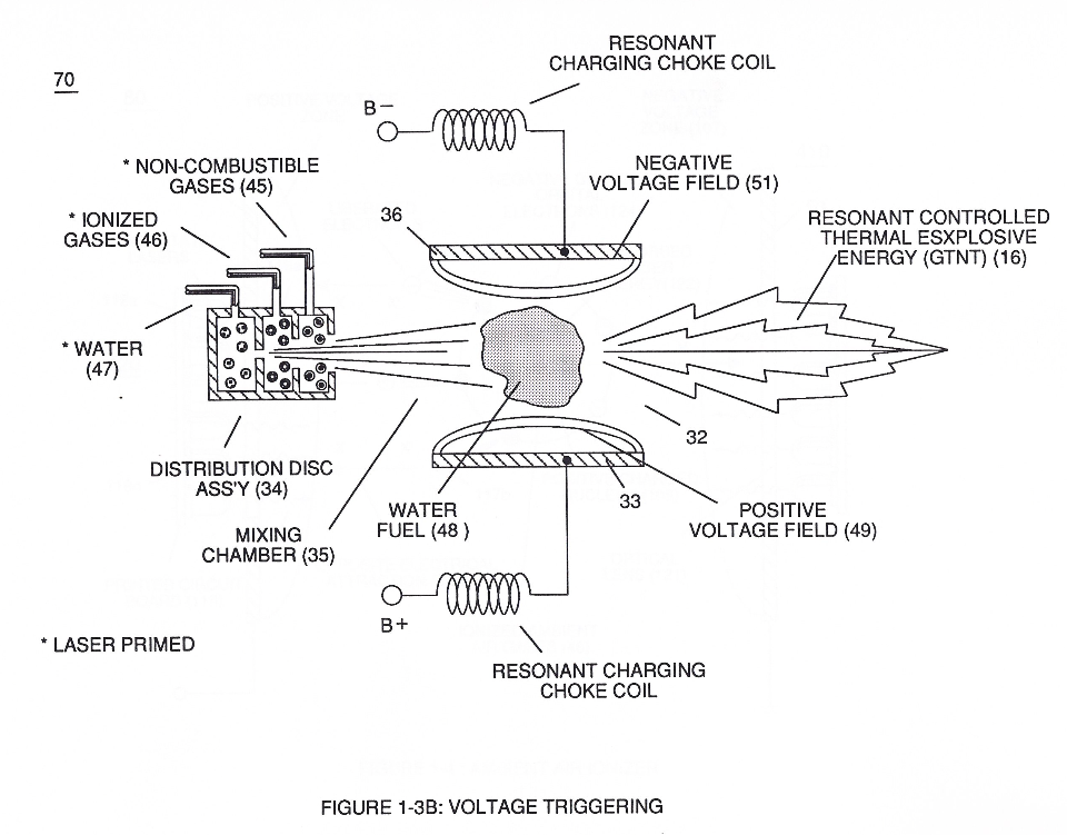
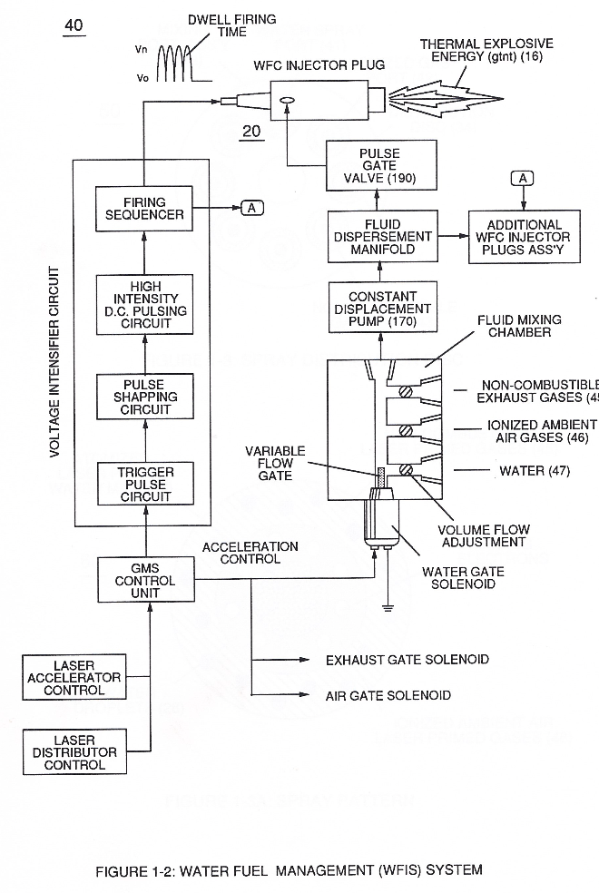
… ic Resonant (240) of Figure (30); but, also sets up and triggers Hydrogen Fracturing Process (390) of Figure (41) as to Figure (6) under control state (on demand) via electrical-static spark ignition (49 / 51) of Figure (3B)....releasing thermal explosive energy (gtnt) (16) passing beyond gas exit port (32) of Figure (3B), as further illustrated in Figure (2) as to Figure (1).
Water Fuel Injector (Taper Resonant Cavity Chamber) 3×
-
venturi tube-cavity (51)
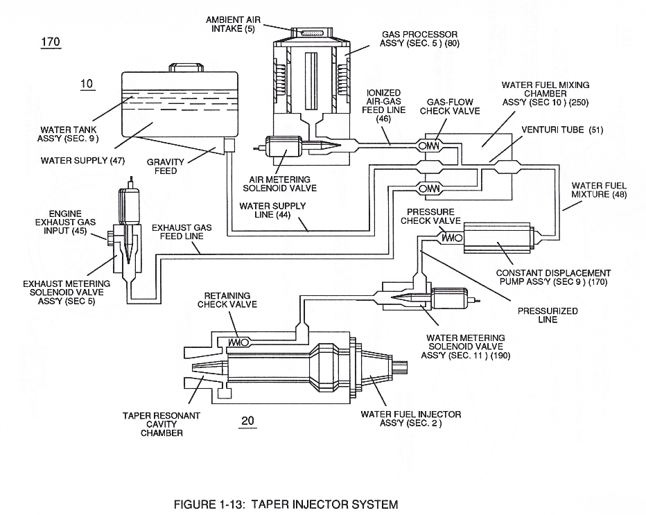
In like manner, water supply (10) of Figure (170), non-combustible gases (45) (Engine Exhaust gases), and ambient air ionized gases (46) (air gases having missing electrons) are uniformly intermixed when moving into, passing through and beyond fluid mixing chamber (250) of Figure (13) by way of venturi tube-cavity (51)...
-
Once water fuel-droplets (xxx 48n) fully occupies open space cavity (Resonant Cavity Zone) (35) and then exposed to applied pulsating opposite electrical voltage fields (49/51) of voltage wave form (280) of Figure (17), the electrically stimulated water fuel droplets (48a xxx 48n) are subjected to release thermal explosive energy (gtnt) (16) undergoing Electrical-Resonant in a sequential manner: