(67)
Opposite Polarity
Also written applied voltage Potential of opposite polarity · applied voltage pulse of opposite polarity · voltage zones · Negative Voltage Potential · applied voltage Potential · Voltage Potential · Applied voltage fields · Excitor-Array and 18 more
Where it is first named
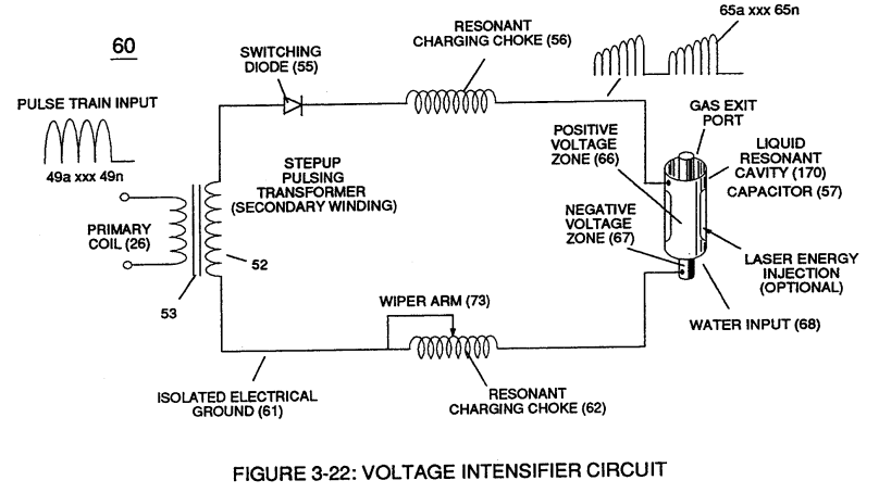
Negative electrical voltage potential (61) of pulse wave (65a xxx 65n) of Figure (3-21) is simultaneously applied to negative voltage zone (67) via Resonant Charging Choke (62) of Figure (3-22) which is electrically linked to opposite end of Primary Coil (26).
How it is written
- (66/67) 27× with (66) Positive Voltage Potential
- (67) 11×
- (66/E9 – 67/E10) 1× with (66) Positive Voltage Potential, (E9) Capacitor, (E10) Capacitor
- (66-El/67-E2) 1× with (66) Positive Voltage Potential, (El) Applied voltage fields, (E2) Voltage Zones
- (66/Ell-67/E12) 1× with (66) Positive Voltage Potential, (Ell), (E12)
- (66- Vpa/Vpb - 67- Vpa/Vpb) 1× with (66) Positive Voltage Potential, (Vpa) Voltage Amplitude Burst-Time, (Vpb) Voltage Amplitude Burst-Time
- (67/66) 1× with (66) Positive Voltage Potential
- (67/E10) 1× with (E10) Capacitor
Drawings 189
-
Figure (3-22) · Analog Voltage generator (40)
-
Figure (3-22) · Voltage Amplitude Control Circuit (50)
-
Figure (3-26) · Voltage Intensifier Circuit (60)
-
Figure (3-25) · Voltage Intensifier Circuit (60)
-
Figure (3-22) · Voltage Intensifier Circuit (60)
-
Figure (3-22) · Voltage Dynamics
-
In both cases, electrical charge deflection or movement is directly related to applied voltage (65). · Voltage Dynamics
-
Figure (3-29) · Electrically Charged Water Molecule
-
Figure (3-26) · Electrically Charged Water Molecule
-
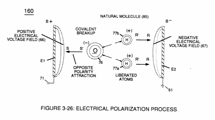
At the same time stationary "negative" electrical voltage field (67) (voltage plate E2) attracts positive charged hydrogen atoms (77a/b). · Electrical Polarization process
-
Figure (3-30) · Resonant Action
-
Figure (3-39) · Resonant Action
-
Voltage Intensifier Circuit (60) of Figure (3-22) · Gas Processor
-
Carries this number · WFC 422DA - Illustrations
-
Carries this number · WFC 422DA - Illustrations
-
Carries this number · WFC 422DA - Illustrations
-
Carries this number · WFC 422DA - Illustrations
-
Carries this number · WFC 422DA - Illustrations
-
Carries this number · WFC 422DA - Illustrations
-
Carries this number · WFC 422DA - Illustrations
-
Carries this number · WFC 422DA - Illustrations
-
3-4 Inner Core Bobbin · Voltage Intensifier Coil Assembly
-
Carries this number · Electronic Circuit Design
-
Carries this number · Water Fuel Injector (Taper Resonant Cavity Chamber)
-
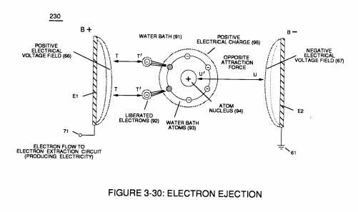
Electron Ejection Process (230) of Figure (29) · Water Fuel Injector (Taper Resonant Cavity Chamber)
-
Figure (25) · Water Fuel Injector (Taper Resonant Cavity Chamber)
-
(520) of Figure (4-3) · Funneling Effect
-
Carries this number · Funneling Effect
-
(650) of Figure (7-4) · Amp Inhibiting Circuit Vs Voltage Enhancement
-
Carries this number · Steam Resonator Assembly
-
(160) of Figure (3-26) · Water Fuel Injection System - Page 1
-
Figure (3-30) · Water Fuel Injection System - Page 2
-
Carries this number · Energy Pumping Action
-
Figure (5-1) · Energy Pumping Action
-
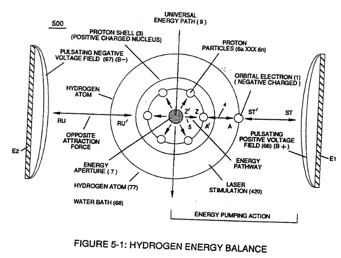
This established increase or decrease in Electrical Pressure (4 / 5 ), now causes Energy Aperture (7) to either enlarge or become smaller as to applied voltage amplitude (VO xxx Vn), respectively. · Energy Pumping Action
-
Carries this number · Energy Pumping Action
-
Carries this number · Energy Pumping Action
-
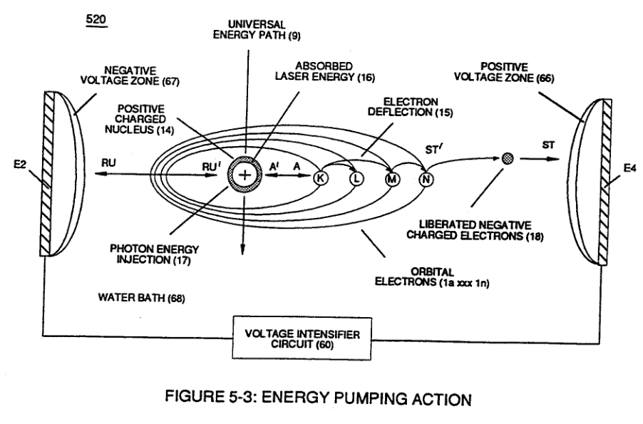
(520) in Figure (5-3) · Resonant Propagation
-
(85) of Figure (3-26) · In Application of Usage
-
(520) of Figure (5-3) · In Application of Usage
-
(160) of Figure (3-26) · In Application of Usage
-
(500) of Figure (5-1) · In Application of Usage
-
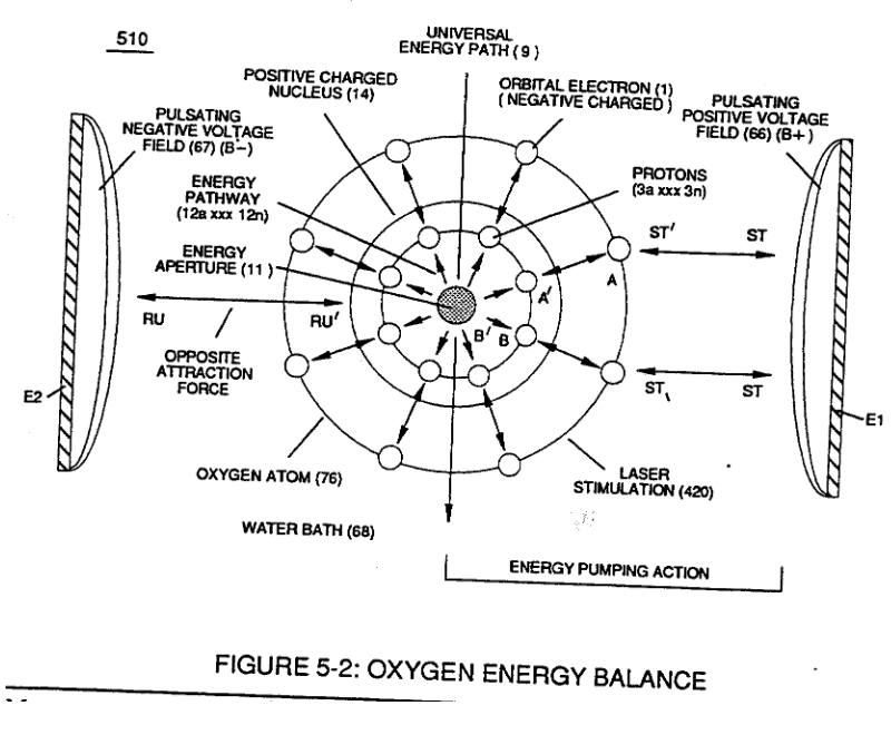
(510) of Figure (5-2) · In Application of Usage
-
(230) of Figure (3-30) · In Application of Usage
-
(57) of Figure (6-2) · In Application of Usage
-
(520) of Figure (5-3) · Solar Energy Actuator
-
Carries this number · Illustrations
-
Carries this number · Illustrations
-
Carries this number · Illustrations
-
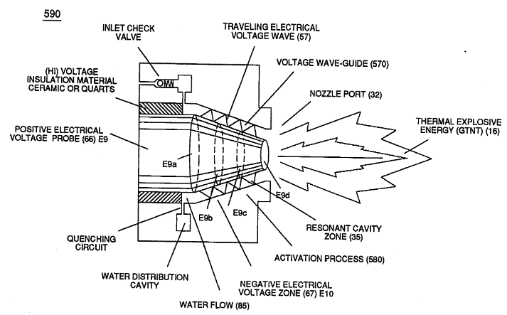
Activation Process (590) of Figure (6-2) · Voltage Intensifier Coil-Assembly
-
Hydrogen Fracturing Process (520) of Figure (5-3) · Voltage Intensifier Coil-Assembly
-
Voltage Intensifier Circuit (60) of Figure (3-22) · Instant Explosion of Water
-
(56/62) of Figure (3-22) · Instant Explosion of Water
-
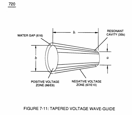
(616) of Figure (7-11) · Instant Explosion of Water
-
(57 of Figure 3- 25 ~35 of Figure 6-2) · Instant Explosion of Water
-
(56) of Figure (3-22) · Instant Explosion of Water
-
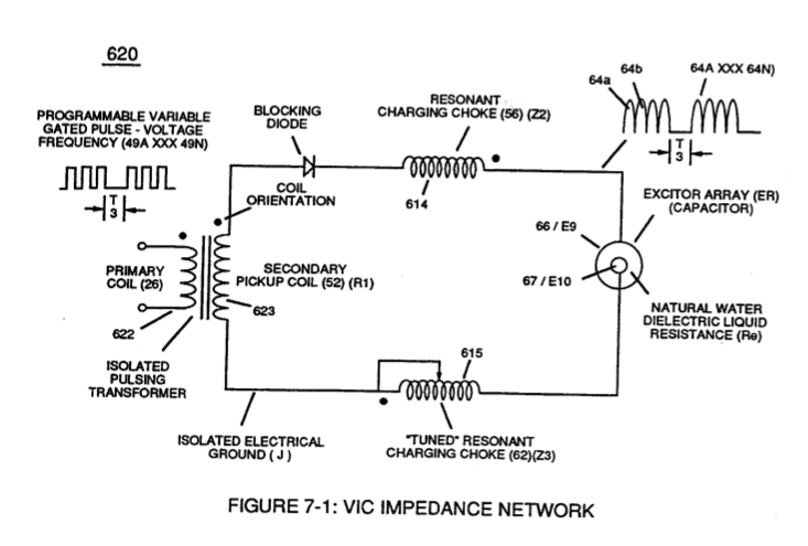
(620) of Figure (7-1) · Instant Explosion of Water
-
(85) of Figure (3-26) · Resistance (Rs)
-
(650) of Figure (7-4) · Resistance (Rs)
-
(620) of Figure (7-1) · Resistance (Rs)
-
(614) of Figure (7-1) · Inductance (FL)
-
(720) of Figure (7-11) · Inductance (FL)
-
(720, 616) of Figure (7-11) · Inductance (FL)
-
Carries this number · Inductance (FL)
-
Inductor (614) of Figure (7-1) · Inductance (FL)
-
Capacitor (E9/E10) of Figure (7-11) · Inductance (FL)
-
(650) of Figure (7-4) · Inductance (FL)
-
(614) of (7-1) · Inductance (FL)
-
Figure (3-24) · Inductance (FL)
-
(720) of Figure (7-11) · Capacitance (Cd)
-
(650) of Figure (7-4) · Capacitance (Cd)
-
(590) of Figure (6-2) · Capacitance (Cd)
-
(620) of Figure (7-1) · Inductance Reactance (Rs - Cd - FL)
-
(730) of Figure (7-12) · Taper Resonant Capacitor (ERt)
-
diagram 720 of Figure 7-11 · Taper Resonant Capacitor (ERt)
-
"Voltage Deflection" of Figure (7-4) · Capacitance Reactance
-
Opposite Electrical Attraction Force (SS' ~ 617 ~ RR' - T3 - SS' ~ 617 - RR') of Figure (7-4) · Electron Bounce Phenomenon
-
Voltage Dynamics (220) of Figure (3-29) · Electron Bounce Phenomenon
-
Traveling Electrical Voltage Wave-forms (730a - b - c) of Figure (7-12) · Electron Bounce Phenomenon
-
(E9/10) of Figure (6-2) · Voltage Amplitude Switch-Off
-
Compressional Wave-form (B) of Figure (7-12) · Voltage Amplitude Switch-Off
-
Carries this number · Mode of Operability
-
Carries this number · WFC 426 - Illustrations
-
Carries this number · WFC 426 - Illustrations
-
Carries this number · WFC 426 - Illustrations
-
(730A) of Figure (7-12) · 8-2 - Traveling Voltage Wave-Guides
-
(780A) Figure (8-2) · 8-2 - Traveling Voltage Wave-Guides
-
(570) of Figure (7-12) · 8-2 - Traveling Voltage Wave-Guides
-
(720) of Figure (7-11) · 8-2 - Traveling Voltage Wave-Guides
-
Carries this number · 8-2 - Traveling Voltage Wave-Guides
-
(520) of Figure (5-3) · 8-2 - Traveling Voltage Wave-Guides
-
(770) of Figure(8-1) · 8-2 - Traveling Voltage Wave-Guides
-
Figure (8-2) · 8-2 - Traveling Voltage Wave-Guides
-
(770) of Figure (8-1) · 8-3 - Electrical Voltage-Pulse Wave-Transmission
-
(770 A) of Figure (8-1) · 8-4 - State Space (Sp)
-
(650) of Figure (7-4) · 8-4 - State Space (Sp)
-
(770 B) of Figure (8-1) · 8-4 - State Space (Sp)
-
(780 B) of Figure (8-2) · 8-4 - State Space (Sp)
-
780 A · 8-4 - State Space (Sp)
-
Carries this number · 8-4 - State Space (Sp)
-
Carries this number · 8-4 - State Space (Sp)
-
(585) of Figure (8-1) · 8-4 - State Space (Sp)
-
(510) of Figure (5-2) · 8-4 - State Space (Sp)
-
(170) of Figure (3-25) · 8-4 - State Space (Sp)
-
(730) of Figure (7-12) · 8-5 - Energy Vectoring (Ev)
-
(770A) of Figure (8-1) · 8-5 - Energy Vectoring (Ev)
-
Clipped Voltage Wave-form (780C) of Figure (8-2) · 8-5 - Energy Vectoring (Ev)
-
Carries this number · 8-5 - Energy Vectoring (Ev)
-
(612) of Figure (8-1) · 8-5 - Energy Vectoring (Ev)
-
Carries this number · 8-6 - VIC Voltage Sync-Pulse Circuit
-
Carries this number · 8-6 - VIC Voltage Sync-Pulse Circuit
-
(650) of Figure (7-4) · 8-6 - VIC Voltage Sync-Pulse Circuit
-
(730A) of Figure (7-12) · 8-7 - Application of Usage
-
Carries this number · WFC 427 Illustrations
-
Carries this number · WFC 427 Illustrations
-
Energy Pumping Action (520) of Figure (5-3) · WFC Development Objectives
-
Carries this number · WFC Development Objectives
-
Carries this number · WFC Exhaust Air Reclaimer
-
Voltage Dynamics (220) of Figure (3-29) · WFC Exhaust Air Reclaimer
-
"Voltage Tickling of State Space" (770A) of Figure (8-1) · WFC Exhaust Air Reclaimer
-
"Voltage Tickling of State Space" (770B) of Figure (8-1) · WFC Exhaust Air Reclaimer
-
Voltage Intensifier Circuit (60) of Figure (3-22) · Propagating Electrical Stress
-
(160) of Figure (3-26) · Propagating Electrical Stress
-
Carries this number · Propagating Electrical Stress
-
(60) of Figure (3-22) · Propagating Electrical Stress
-
Figure (5-2) · Propagating Electrical Stress
-
The programmable pulse-frequency (49a xxx 49n) of Figure (10-1) input is simply adjusted to tune-in to the dielectric property of the Water Molecule. · Propagating Electrical Stress
-
Dynamic Electrical Charging Effect (612) of Figure (8-1) · Propagating Electrical Stress
-
Energy Priming Stage (500) of Figure (5-1) · Propagating Electrical Stress
-
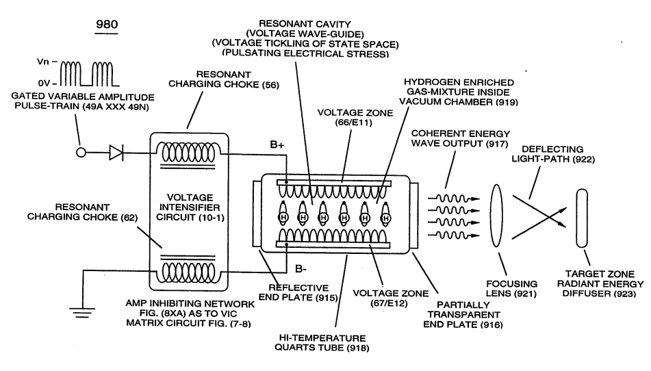
... emitting Coherent Energy Wave-Form (917), as so illustrated in (980) of Figure (10-2). · Optical Thermal Lens
-
Carries this number · Quartz Tube Configuration & Operational Parameters
-
Carries this number · Quartz Tube Configuration & Operational Parameters
-
Carries this number · Quartz Tube Configuration & Operational Parameters
-
... establishing variable Dynamic Electrical Charging Effect (612). · Quartz Tube Configuration & Operational Parameters
-
Carries this number · WFC 429 - Illustrations
-
Carries this number · WFC 429 - Illustrations
-
WFC Figure (5-1) · WFC Atomic Degaussing Process
-
Carries this number · Wobbling Effect
-
energy aperture (7) of Figure (5-1) · Voltage Flexing Process
-
(500) of Figure (5-1) · Voltage Flexing Process
-
(970) of Figure (10-1) · VIC Switchover Circuit
-
Figure (3-21) · Voltage Amplitude Control Circuit (50)
-
Figure (3-28) · Voltage Intensifier Circuit (60)
-
Ohm's law of LC circuit (180) of Figure (3-28) in series is given by (Eq 5) · Voltage Intensifier Circuit (60)
-
Voltage (Vc) of Figure (3-28) across the capacitor is given by (Eq 7) · Voltage Intensifier Circuit (60)
-
Figure (3-21) · Voltage Intensifier Circuit (60)
-
Figure (3-23) · Voltage Intensifier Circuit (60)
-
The figure it sits on · Voltage Dynamics
-
Figure (3-23) · Voltage Dynamics
-
The figure it sits on · Gas Processor
-
The figure it sits on · WFC 422DA - Illustrations
-
The figure it sits on · WFC 422DA - Illustrations
-
The figure it sits on · WFC 422DA - Illustrations
-
Gas Processor Assembly 2 · Differential Air-Gas Inlet Control
-
The figure it sits on · Differential Air-Gas Inlet Control
-
"Voltage Intensity of Opposite Potential" (600) of Figure (6-3) · Voltage Intensifier Coil-Assembly
-
(190) of Figure (3-23) · Tri - Coil Construction
-
The figure it sits on · WFC 425 - Illustrations
-
The figure it sits on · VIC Matrix Circuit
-
Voltage Intensifier Circuit (620) of Figure (7-1) · Instant Explosion of Water
-
(T2) of Figure (7-8) · Instant Explosion of Water
-
Figure (7-8) · Resistance (Rs)
-
(690) of Figure (7-8) · Resistance (Rs)
-
(600) of Figure (6-3) · Inductance (FL)
-
(690) of Figure (7-8) · Inductance (FL)
-
(600) of Figure (6-3) · Inductance (FL)
-
Figure (7-1) · Capacitance (Cd)
-
(690) of Figure (7-8) · Capacitance (Cd)
-
(690) of Figure (7-8) · Inductance Reactance (Rs - Cd - FL)
-
Inductance Pulsing-Core (190) of Figure (3-23) · Inductance Reactance (Rs - Cd - FL)
-
Figure (7-8) · Inductance Reactance (Rs - Cd - FL)
-
(690) of Figure (7-8) · Taper Resonant Capacitor (ERt)
-
(see diagram 720 of Figure 7-11) · Taper Resonant Capacitor (ERt)
-
690 of Figure 7-8 · Circuit Resistance
-
Choke-Coil (62) of Figure (7-1) · Transformer Action
-
The figure it sits on · Electron Bounce Phenomenon
-
(52) of Figure (7-8) · Electron Bounce Phenomenon
-
The figure it sits on · WFC 426 - Illustrations
-
The figure it sits on · 8-1 - Propagating "Resonant Action" By Voltage Tickling of State Space
-
(690) of Figure (7-8) · 8-2 - Traveling Voltage Wave-Guides
-
(52) of Figure (7-8) · 8-3 - Electrical Voltage-Pulse Wave-Transmission
-
(Cp) of Figure (7-8) · 8-4 - State Space (Sp)
-
(780 A/B/C) of Figure (8-2) · 8-4 - State Space (Sp)
-
(620) of Figure (7-1) · 8-6 - VIC Voltage Sync-Pulse Circuit
-
(690) of Figure (7-8) · 8-6 - VIC Voltage Sync-Pulse Circuit
-
(Cp) of (7-8) · 8-6 - VIC Voltage Sync-Pulse Circuit
-
(690) of Figure (7-8) · Propagating Electrical Stress
-
"Resonant Charging Choke" (56) of Figure (7-1) · Propagating Electrical Stress
-
(620) of figure (7-1) · Voltage to Amp Differential Ratio
Where it is named · 47
Voltage Intensifier Circuit (60) 7×
-
Excitor-Array (66/67)
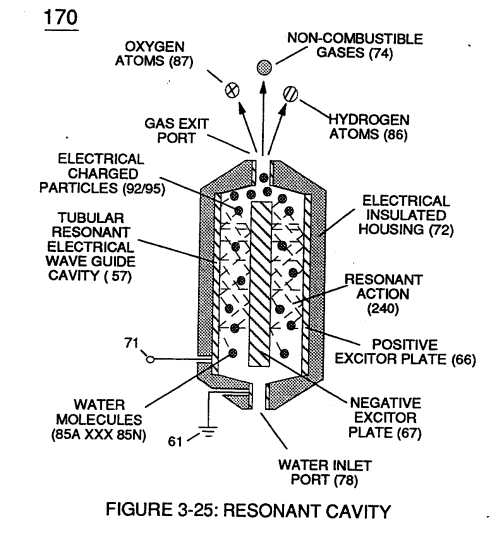
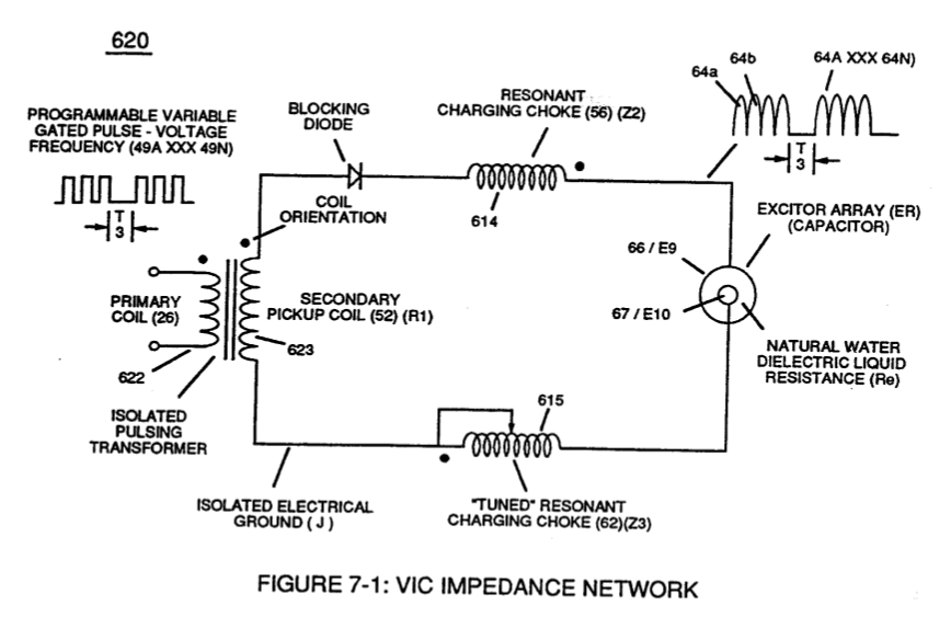
Resonant charging choke (56) in series with Excitor-Array (160) of Figure (25) forms an inductor-capacitor circuit (180) of Figure (3-28) since Excitor-Array (66/67) acts and performs as a capacitor (dielectric liquid between opposite electrical plates) during pulsing operations.
-
electrical plates (66/67)
(dielectric constant of water being 78.54 @ 20C in 1-atm pressure) between electrical plates (66/67)
Voltage Dynamics 2×
-
negative (67)
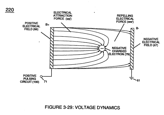
These electrical "forces" are known as ''voltage fields" and can exhibit either a positive (66) or negative (67) electrical charge.
-
voltage zones (66/67)
Furthermore, electrical charged ions or particles can move toward stationary voltage fields or voltage zones (66/67) of opposite polarity, and, is given by Newton's second law (Eq 12)
Electrically Charged Water Molecule 1×
Electrical Polarization process 1×
-
electrical voltage field (67)
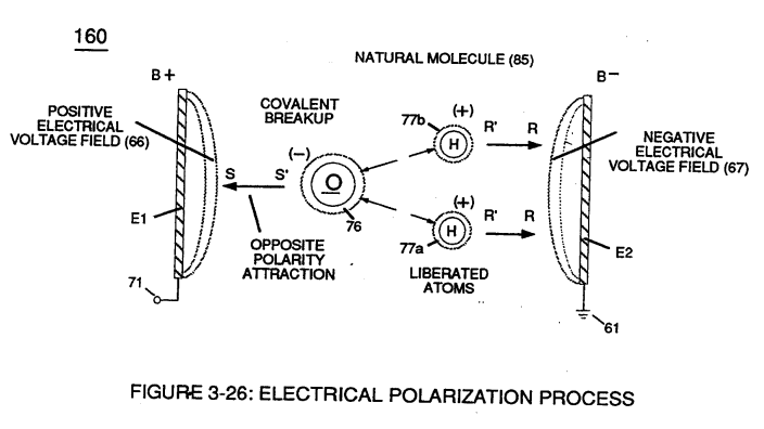
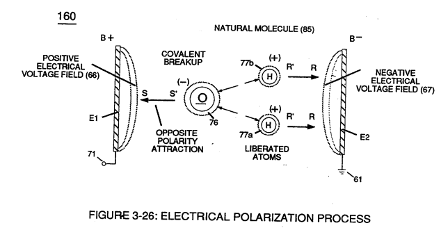
At the same time stationary "negative" electrical voltage field (67) (voltage plate E2) attracts positive charged hydrogen atoms (77a/b).
Resonant Action 4×
-
To reach maximum gas-yield (88) resonant cavity (170) of Figure (3-25) is shaped into a tubular structure (typically 0.50 inch diameter tube inserted into 0.75 inch diameter tube having a .0625 concentric air-gap 3 inches long) which functions as a longitudinal wave-guide to enhance particle movement in a lateral or angular displacement to applied voltage fields (66/67).
-
voltage intensity (66/67)
In cases where applied voltage amplitude is to remain constant while promoting Resonant Action during control-state, incoming pulse train (64a xxx 64n) is varied independent of voltage amplitude to attenuate voltage intensity (66/67) which, in turn, effects gas production.
-
Voltage amplitude (66/67)
In other applications, Voltage amplitude (66/67) in direct relationship to pulse-train (64a xxx 64n) may be varied together in a progressive manner to further control gas production. Or pulse-train (64a xxx 64n) can remain constant while voltage amplitude is varied.
Water Fuel Injector (Taper Resonant Cavity Chamber) 1×
-
Resonant coil-Tap (67)
The "Plus Factor" is that induce external electromagnetic field (63/64) across Resonant coil-Tap (67) increases voltage intensity (voltage potential) still further rather than diminishes peak voltage potential due to resistive valve of the stainless steel wire.
Energy Pumping Action 6×
-
Applied voltage fields (66-El/67-E2)
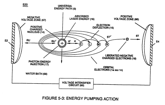
Applied voltage fields (66-El/67-E2) causes and forms both opposite attraction forces (ST - ST') and (RU - RU') across exposed Hydrogen Atom (77) since the negative charged hydrogen electron (1) is attracted and deflected toward stationary positive voltage field (66);
-
stationary voltage field (67)
...while, simultaneously, positive charged hydrogen proton (3) (Hydrogen Nucleus) is attracted and moved in opposite direction toward stationary voltage field (67)
-
applied voltage fields (66/67)
Interlocked together, the resultant "Electrical Tension of Forces" (4/5) is directly related to Voltage Intensity (ST - ST' / RU - RU' ) of applied voltage fields (66/67) which is variable as to applied voltage amplitude ( Vo xxx ). Increasing voltage amplitude ( xxx Vn) still further increases electrical tension (4 / 5 ) being applied to Energy Aperture (7) or vice versa.
-
applied voltage pulse of opposite polarity (66/67)
Once applied voltage pulse of opposite polarity (66/67) is terminated during pulse off-time, then Energy Aperture (7) automatically adjusts to maintain a given energy level since each aperture oscillation (aperture expansion) emits a discrete amount of Universal Energy (9) into proton (3) via energy pathway (ZZ'), as illustrated in Figure (5-1).
-
Repetitive pulsing of applied voltage fields (66/67), now, oscillates Energy Aperture (7) to emit even a greater amount of Universal Energy (9a xxx 9n) into the energy spectrum of the proton nucleus (3) to be absorbed ... thereby, increasing the energy level of hydrogen atom still further .... deflecting hydrogen electron (1) to a higher energy state, as illustrated in (520) of Figure (5-3).
-
voltage stimulation (66/67)
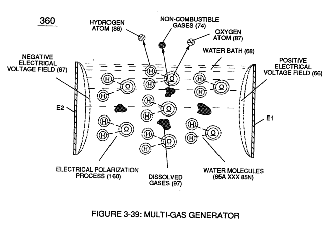
… Likewise, liberated oxygen atom (76) and other dissolved air gases (97) submerged in water bath (68) undergo and experience similar Energy Pumping Action (520) (aperture oscillation) of their respective Energy Aperture (11a xxx 11n) when exposed to voltage stimulation (66/67), as further illustrated in Figure (5-2).
In Application of Usage 1×
-
… gure (3-30) as to (270) of (3-34) ionizes the highly energized combustible gases to decrease atomic mass while applied traveling voltage wave-form (57) of Figure (6-2) of opposite electrical polarity (E9-66/ ElO-67) initiates the voltage-triggering process (600) of Figure (6-3) once maximum voltage deflection (VO - Va - Vb - Vc - Vn) of Figure (6-4) is achieved at Activation-Point (E9d) of Figure (6-2) ... …
Water Fuel Injector 1×
-
while, at the same time, negative potential of electrical intensity of force (67) (negative voltage potential) is electrically directed to inner conical surface (E1O), forming an "open-air" conical cavity (570) having parallel sides (in other cases non-linear voltage-surfaces) in space relationship (typically .010 gap) with diminishing circumference-area (E9a xxx E9n) / E10a xxx E10n) in linear progression.
Resistance (Rs) 2×
Inductance (FL) 1×
-
inner tapered surface (67)
Capacitor (E9/E10) of figure (6-2) as to (720) of Figure (7-11) is formed when outer tapered surface (66) and inner tapered surface (67) forms Water-Gap (616) of Figure (7-11) as to Figure (590) of Figure (6-2) having placed there between Dielectric Water Bath (85/Re), as schematically illustrated in matrix outline in (670) of Figure …
Capacitance (Cd) 4×
-
applied voltage Potential (66/67)
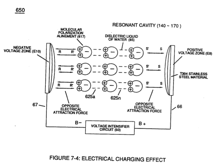
... a resistive liquid (having an ohmic value of 78.54 ohms) that takes on an "Electrical Charge" when applied voltage Potential (66/67) of Figure (7-1) as to (650) of Figure (7-4) causes and sets up Molecular Polarization Alignment (617) of Figure (7-4) by way of electrical molecular rotation (opposite electrical attraction force to rotate and position particle alignment) of each water Molecule (85a - 85b - 85c - 85n). …
-
-
applied voltage Potential of opposite polarity (66/67)
… forms capacitor (ER) of Figure (7-1) when the dielectric liquid of water (85) is placed or injected between electrical conducting plates (E9/E10) while applied voltage Potential of opposite polarity (66/67) is directly exposed to Water Molecules (85a xxx 85n), as depicted in Taper Resonant Cavity (590) of Figure (6-2) as to (650) of Figure (7-4).
Inductance Reactance (Rs - Cd - FL) 2×
-
… only further electron-flow restriction (Rp1/Rp2) to both Inductor Chokes (56/62) but automatically increases voltage potential (xxx V g xxx Vh xxx Vn) of opposite voltage intensity of equal magnitude (66/67) across Resonant Cavity (140 -170)
In-Line Circuit Components 1×
-
Voltage Potential (66/67)
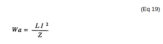
Lengthening Inductor (L1/L2) lengths applies an even higher Voltage Potential (66/67) across Resonant Capacitor (140 -170) (ER) since Inductance Reactance "Stores" Energy and, is expressed by:
8-2 - Traveling Voltage Wave-Guides 4×
-
negative electrical voltage surface (67/E10)
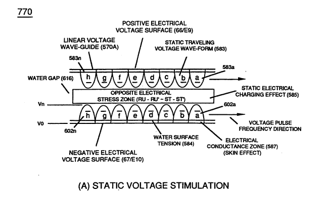
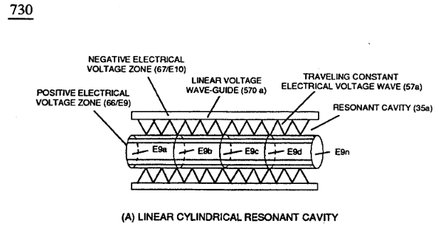
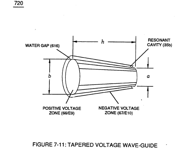
… ing Voltage Wave-guide (570a) of Figure (7-12) (WFC Memo 426) as to (770) of Figure (8-1) is physically formed when positive electrical voltage surface (66/E9) and negative electrical voltage surface (67/E10) are placed in parallel space relationship to form voltage surfaces (E9/E10) about an cylindrical axis of rotation having space-gap (35) there between and thus, fanning Cylindrical Resonant Cavity (73 …
-
opposite polarity (67/66)
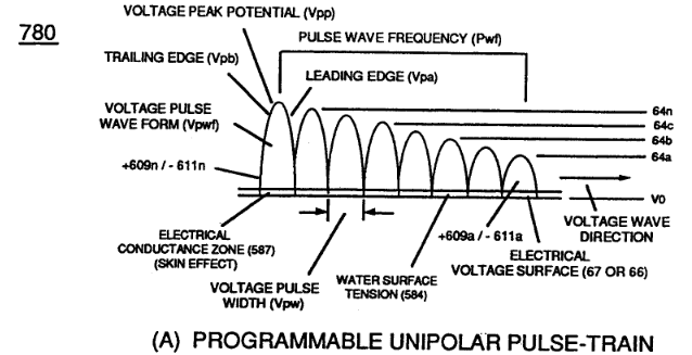
… (730A) of Figure (7-12) as to (770A) of Figure (8-1) when space-gap (616) of Figure (720) exposes injected water bath (85) to unipolar pulse-oscillation of high voltage intensity of opposite polarity (67/66) as to (780) of Figure (8-2) which, in turn, propagates opposite electrical attraction force (RR' _ 88') of Figure (7-4), as illustrated in (590) of Figure (6-2) as to (585) of Figure (8-1).
8-3 - Electrical Voltage-Pulse Wave-Transmission 1×
-
Negative Electrical Voltage Intensity (67)
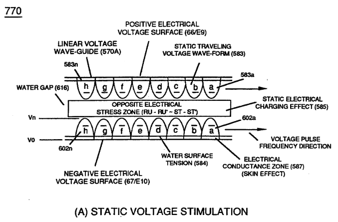
Opposite negative Voltage Pulse Train (67 - 602a xxx 602n) is similarly formed since "Electron Clustering Effect" (631) of Figure (7-9) produces a "Negative Electrical Voltage Intensity (67) in equal magnitude to the "Positive Electrical Voltage Intensity (66) during each/repetitious magnetic pulse-cycle (Rp/71). …
8-4 - State Space (Sp) 3×
-
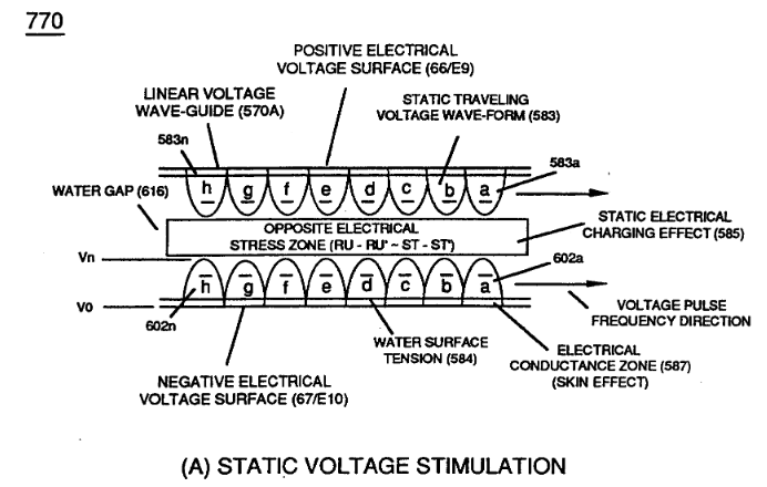
During the electrical-formation (66- Vpa/Vpb - 67- Vpa/Vpb) of each opposite Electrical Voltage-Wave (66-583 - 67-602), opposite electrical attraction force (RR' - SS') of Figure (7-4) is produced across water cap (Cp) of Figure (7-8) which, now, sets up and defines the conditions of “State Space," as illustrated in (770 A/B) of Figure (8-1) as to (650) of Figure (7-4).
-
Electrical Voltage-Wave (66-583 - 67-602)
During the electrical-formation (66- Vpa/Vpb - 67- Vpa/Vpb) of each opposite Electrical Voltage-Wave (66-583 - 67-602), opposite electrical attraction force (RR' - SS') of Figure (7-4) is produced across water cap (Cp) of Figure (7-8) which, now, sets up and defines the conditions of “State Space," as illustrated in (770 A/B) of Figure (8-1) as to (650) of Figure (7-4).
-
Pulse Wave-Form (66- 583/67-602)
Electrical Attraction Force intensity (RR' - SS' as to RU/RU' - ST/ST' as to 550 of Figure 5-8) at Peak Voltage Potential (Vpp) is either increasing or decreasing or remaining constant as to Voltage Peak Excursion Point "P" trace-position which scans the exact Pulse Wave-Form (66- 583/67-602) being produced, as illustrated in (780B) of Figure (8-2).
Propagating Electrical Stress 2×
-
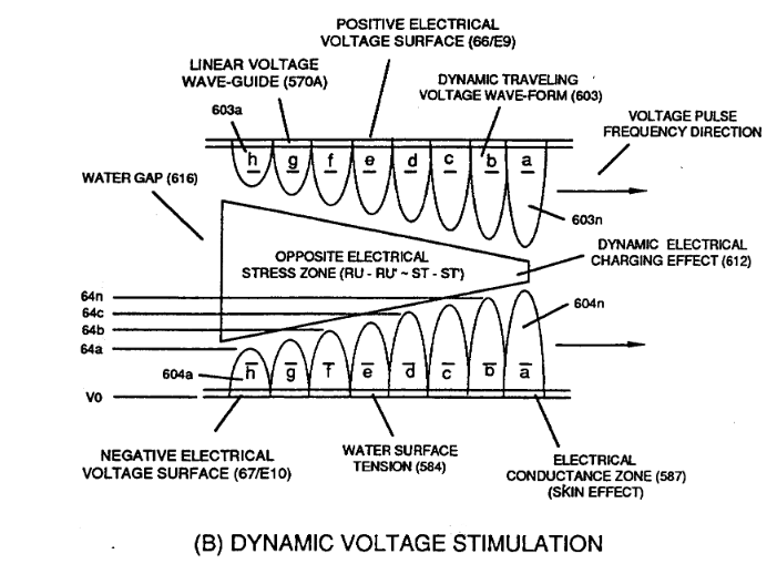
... thereby, preventing amp "in-fluxing" (discouraging electron arc over) across Dielectric Capacitor Gap (ER)(66/67) while Electrical Stress (ST-ST' - RU-RU') of Opposite Voltage Polarity (B+/B-) brings on Energy Priming Stage (520) of Figure (5-3) which is refer to, herein, as "Voltage Tickling of State Space."
-
… occur across capacitor Gap (Cp) while "Voltage Pulse-Potential" (Va xxx Vn/49a xxx 49n) of "Opposite polarity" (B+/B-) is/are allowed to be applied across "Electrical Voltage Plates" (Voltage-Zones) (66/67).
Quartz Tube Configuration & Operational Parameters 3×
-
Voltage Wave-Guides (66/67)
The Electrical Conduction Zone (587) (Skin Effect) between the dielectric gas medium (919) and the Electrical Contact Surface of the inside surface area of the Voltage Wave-Guides (66/67) allows Unipolar Pulse Train (583a/602a-583b/602b - 583n/602n) to travel the entire length of the Voltage Wave Guides that make up Voltage Zones (66/E9 – 67/E10).
-
Voltage Zones (66/E9 – 67/E10)
The Electrical Conduction Zone (587) (Skin Effect) between the dielectric gas medium (919) and the Electrical Contact Surface of the inside surface area of the Voltage Wave-Guides (66/67) allows Unipolar Pulse Train (583a/602a-583b/602b - 583n/602n) to travel the entire length of the Voltage Wave Guides that make up Voltage Zones (66/E9 – 67/E10).
-
... thereby, establishing functional parameters of Optical Thermal Lens (980) of Figure (10-2) when Voltage Intensifier Circuit (VIC Circuit) (10-1) is electrically connected to Voltage Zones (ER) (66/Ell-67/E12).