

patent · EP0007697A1
Burner system for gaseous and/or liquid fuels with a minimum production of NOx
6 February 1980
Text
Page 1bibliographic recordscan →
Patentamt a i s c h e Patent
J E u r o p European s Office Publication number: 0 007 697 Office europeen des brevets A1
E U R O P E A N PATENT A P P L I C A T I O N
(g) Application number: 79301160.2 (St) IntCI.3: F 23 D 1 7 / 0 0
Priority: 19.06.78 US 916766 Applicant: JOHN ZINK COMPANY 4401. South Peoria
Tulsa, Oklahoma. 74105(US) (43) Date of publication of application:
06.02.80 Bulletin 80/3 (g) Inventor: Reed, Robert D. 4339 South Peoria (5) Designated Contracting States: Tulsa, Oklahoma(US)
Representative: Kerr. SImonne June et al, c/o POTTS, KERR & CO. 27, Sheet Street
Windsor, Berkshire SL4 IBY(GB)
(5) Burner system for gaseous and/ or liquid fuels with a minimum production of NOx. A low NOx burner (10) for a furnace operating under natural draught in which primary and secondary combustion air (60, are provided to a first burning zone (16,18) in which either or both liquid and gaseous fuel can be used. Less than stoichiometric air is supplied in the primary burning zone (16, 18 and tertiary combustion air (50) is supplied in a second cor bustion zone (28) downstream from the first combustion zon(16, 18). The total air supply is over the stoichiometric requirement. Air control means (38,40,42 and is provided so that a fixed ratio of primary-secondary air/tertiary air is provided for all burning and fuel rate conditions, so as to maintain the less than stoichiometric air supply to the first combustion zone. In addition, water atomization (68, 70, 88 and is provided upstream of the first burning zone (16,18) to provide a burning chemistry which factors the reduction of NOx in the first burning zone.
Page 2scan →
This invention lies in the field of l i q u i d and gaseous fuel burning. More p a r t i c u l a r l y , this invention concerns fuel burning apparatus in which the design of the burner and control of the fuel and a i r supply is such as to maintain a minimum value of NOx in the effluent gases.
The b u r n i n g of f u e l s , however it is accomplished in burners, as they are known in the art of f u e l burning, is productive of o x i d e s of n i t r o g e n ( N O x ) in normal operations. Such o x i d e s of n i t r o g e n as are produced in combination with olefinic hydrocarbons which may be p r e s e n t in the atmosphere
Smog, while not necessarily lethal, is recognized universally as p o t e n t i a l l y damaging to animal tissue. Consequently, severe limitations on the NOx c o n t e n t of stack gases vented to the atmosphere as a r e s u l t of f u e l s burning, have been imposed by v a r i o u s governmental authorities and agencies. Emission of o l e f i n i c hydrocarbons is also subject to l i m i t a t i o n s , but is a matter separate from t h e invention of t h i s application.
The p r i o r art is best represented by U.S. Patent No. 4,004,875. This patent has been the b a s i s of a w i d e application of low NOx b u r n e r s in the n a t u r a l gas field. Scores of b u r n e r s which are based on t h i s patent are in commercial service, where they have suppressed NOx as intended. However, the optimum operation of t h i s prior patent has b e e n for fixed rates of b u r n i n g , .where a good b a l a n c e can b e provided between the primary and secondary air supplies to a first combustion chamber and the supply of a d d i t i o n a l tertiary air downstream of the first combustion chamber.
The weakness of the prior design is that, for one condition of f u r n a c e draught or f i r i n g rate, the operation is ideal However, when the firing rate changes significantly, such a s from 100% to 80% as is typical of d a i l y process heater firing, there is difficulty in m a i n t a i n i n g NOx s u p p r e s s i o n . The reason for this is that at reduced firing rate for furnace draught remains constant or a p p r o x i m a t e l y so, and i n c r e a s e d airto-fuel ratios destroy the l e s s - t h a n - s t o i c h i o m e t r i c burning zone p r i o r to t e r t i a r y air deliver/entry, which r e s u l t s in 3 less than optimum NOx r e d u c t i o n plus higher than desirable excess air.
What is required is a burner which p r o v i d e s means f o r correction for any c o n d i t i o n of f i r i n g , such as might be required when the furnace daught remains substantially constant as changes in firing rate are made. If such corrections can b e made, the result is continuation of NOx s u p p r e s s i o n and maintenance of optimum excess air for high thermal efficiency. In the prior art burner there is no c o n t r o l of the tertiary air, which is caused to flow by f u r n a c e draught (less than atmospheric pressure within the furnace), while the primary and s e c o n d a r y air also flow for the same r e a s o n . The t o t a l air flow w i l l vary as the square root of the furnace draught. Thus, only one r a t e of fuel burning or f i r i n g rate, at a condition of furnace draught will provide required excess air and NOx suppression. This would seem to i n d i c a t e that control of a i r
What is not immediately evident is, that the air entry control must be p r o p o r t i o n a t e l y controlled for maintenance of a l e s s - t h a n - s t o i c h i o m e t r i c burning zone p r i o r to entry of tertiary air to the less-than-stoichiometric gases, for completion of f u e l burning plus preferred excess air when firing rate is caused to vary. If the conditions as o u t l i n e d are maintained, there is suitable Nox s u p p r e s s i o n in any condition of d r a u g h t and f i r i n g rate, and f u r n a c e excess air remains best for high thermal efficiency. This is to say that control must be p r o p o r t i o n a l and s i m u l t a n e o u s for primary, secondary and t e r t i a r y air for best and most a s s u r e d operation in a l l firing conditions.
An o b j e c t of t h i s invention is to provide low NOx b u r n i n g for a wide range of b u r n i n g rate and c o r r e s p o n d i n g air supply rate.
In t h i s invention a fuel burner system includes means f o r combustion of l i q u i d fuels through a first burner system and gaseous fuels through a second burner system in which l e s s - than-stoichiometric air is supplied and combustion takes place in a f i r s t combustion zone, which is surrounded by tile walls. Tertiary combustion air is provided outside 4 of the tile wall and meets the hot reducing flame issuing from the first combustion zone in a second combustion zone
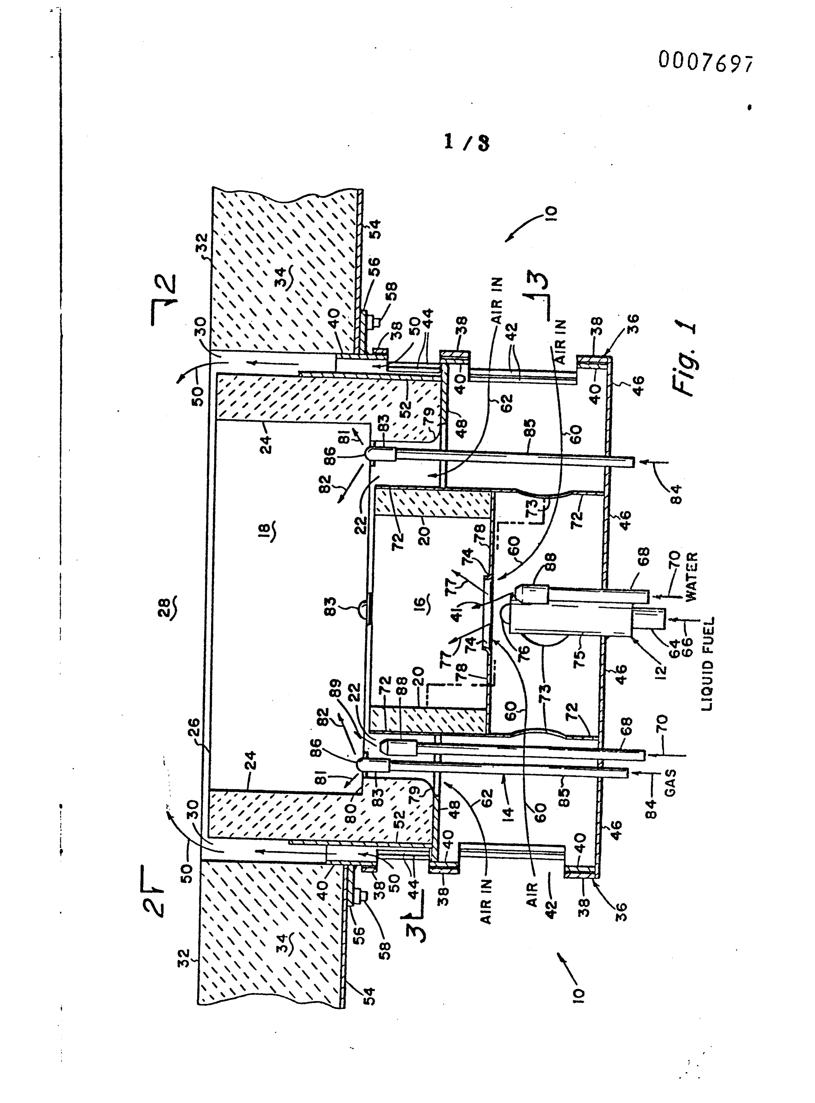
The l e s s - t h a n - s t o i c h i o m e t r i c air supply to the fuel in the first combustion zone produces combustible gases, such as carbon monoxide and hydrogen, which r e a d i l y reduce any NOx t h a t has been formed in the first combustion zone. Additionally, water atomizers are provided, associated with each of the burners and upstream of the flame, to provide additional combustible gases to help in the reduction of any NOx t h a t may be p r e s e n t . As the hot gases with reduced NOx pass downstream into the second combustion zone, tertiary air flows in to complete the combustion but at a reduced temperature so as to minimize additional NOx p r o d u c t i o n . The i n v e n t i o n will now be d e s c r i b e d further, by way o f example, with reference to the accompanying drawings, in which: Fig. 1 is a substantially diametral cross-section of o n e embodiment of this invention; and
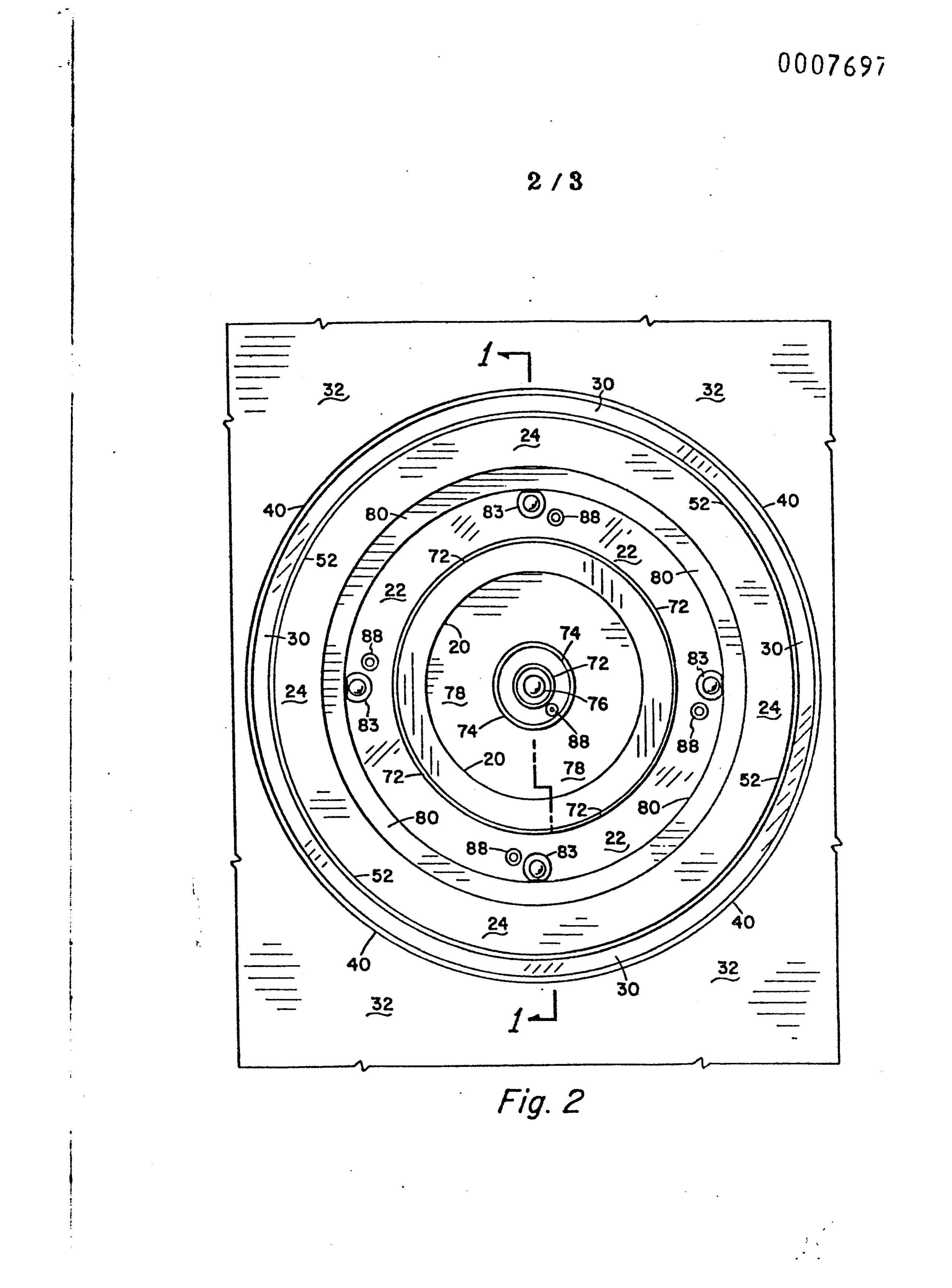
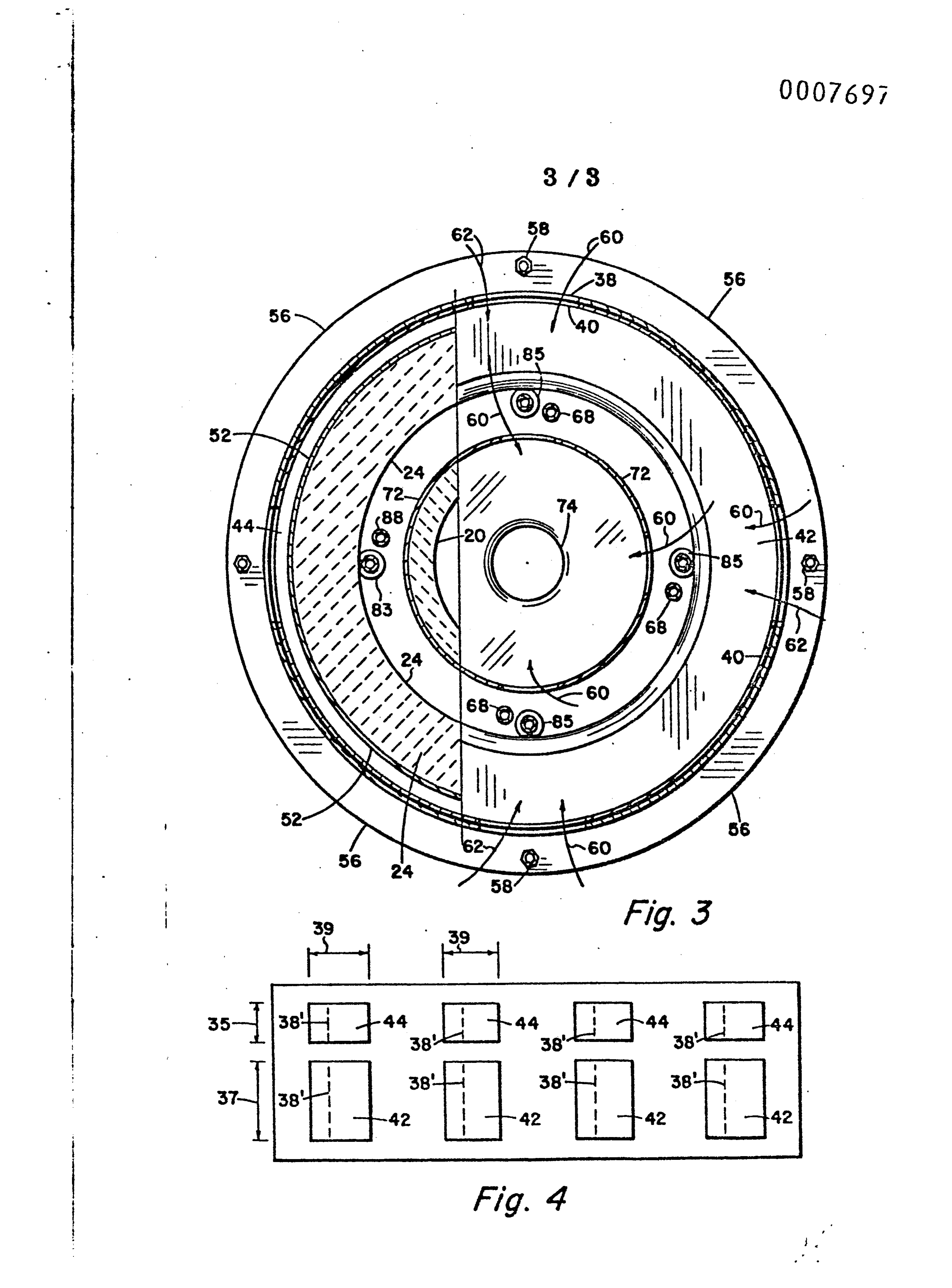
Figs.2 and 3 are transverse cross-sections on the lines 2-2 and 3-3, respectively, of Fig. 1.
The embodiment of t h i s invention to be d e s c r i b e d is designed for alternate or s i m u l t a n e o u s burning of l i q u i d and/or gaseous fuels. A design could be p r o v i d e d which would u t i l i s e solely liquid fuels or gaseous fuels, which might simplify the construction but, in the embodiment to be d e s c r i b e d , simultaneous use of l i q u i d and gaseous fuels is possible.
A liquid fuel burner 12 is mounted a x i a l l y of a b u r n e r system generally indicated by 10. The flame from the liquid burner burns with primary air 60 in a f i r s t combustion area 16 within a cylindrical shell of t i l e 20.
A gaseous fuel burner system is generally indicated by 14. A second cylindrical tile 24 which is of l a r g e r diameter and surrounds the first tile 20 l e a v i n g an a n n u l a r space 22 t h r o u g h which is inserted a plurality of gaseous fuel nozzles 83 t o which gaseous fuel is supplied by pipes 85 in a c c o r d a n c e with arrows 84. The outward flow of gaseous fuel is indicated by arrows 8l and 82 and flows into a second combustion area l8 downstream of 16 and within the cylindrical tile 24. Combustior air flows in accordance with arrow 62 into the annular space 22 5 and past the nozzles 83 to mix with the fuel 81 and 82 and b u r n
A wind box, generally indicated by 36, is provided by two cylindrical metal shells 40 and 38. Shell 40 is attached by welding to a circular annular ring 56, which is attached to t h e outer metal wall 54 of the furnace by means of b o l t s 58, as i s well known in the art. The metal wall 54 s u r r o u n d s the ceramic I wall 34 of the f u r n a c e , the inner surface of which is 32. ! The second shell 38 is adapted to r o t a t e around the outside of shell 40, which is stationary and which is closed off at the upstream end by a c i r c u l a r plate 46.
There are two c i r c u m f e r e n t i a l rows of i d e n t i c a l - width rectangular openings, one row c o n t a i n i n g a plurality of openings 42 and a n o t h e r row c o n t a i n i n g an equal plurality of
This arrangement is shown in Fig. 4, which is a picture of t h e s h e e t s 40 and 38, which are laid out flat to show f o r each of the rectangular openings 42 and for each of the openings 44. The p i c t u r e is drawn with the openings in each of the two sheets identical and f u l l y superimposed. The width 39 of a l l openings is the same and the length of the first row of o p e n i n g s 42 is 37 and the length of the smaller openings 44 is 35. The ratio of the lengths 37 to 35 is made to be e q u a l t o the r a t i o of primary plus secondary air and t e r t i a r y air. For example, the primary air plus secondary air might be 70% of the total air requirement and the t e r t i a r y air would then be a minimum of 30% and p o s s i b l y some l a r g e r number so as to provide a total air supply which is more than the stoichiometric value of t h e entire fuel burning.
As the outer sheet 38 is moved to the right, the edge 3 8 ' tends to cover part of the openings 42 and 4 4 i n the plate 40.
Thus, the total air supply is reduced but the ratio of p r i m a r y and s e c o n d a r y to t e r t i a r y air supplied through the openings 42 and 44, respectively, is held constant no m a t t e r what the total value of combustion air supplied may b e .
The primary air as arrow 60 p l u s , t h e secondary air as arrow 62 flows through the openings 42. Primary air indicated by arrow 60 flows in t h r o u g h openings 73 in a 6 cylindrical metal wall 72, which is used to support the tile 20. Also, a metal plate 78 is provided to support the tile 20, which has a central opening 74 t h r o u g h which the fuel and a i r are supplied to area 16. The r e m a i n d e r of the air due to f l o w through 42 and as a i r 62 s u p p o r t s the combustion of the gaseous fuel in a c c o r d a n c e with arrow 62 by p a s s a g e through the annular space 22 and past the gaseous fuel nozzles 83, of which four are shown, as in F i g s . 2 and 3 .
The second t i l e 24 is supported on a c y l i n d r i c a l shell 52, which is attached to a transverse annular plate 48 w h i c h supports the tile 24. Because of t h i s plate 48 any a i r that passes up through the annular space 30 must come t h r o u g h the opening 44 in a c c o r d a n c e with arrows 50 i n t o the secondary burning zone 28 downstream of the primary combustion zone 1 6 , l8. The corner 79 of the tile 24 is rounded as shown in o r d e r to b e t t e r provide streamlined air flow 62 i n t o the annular
The l i q u i d fuel burner 12 c o m p r i s e s a burner tube 64 t h r o u g h which l i q u i d fuel flows in a c c o r d a n c e with arrows 66. There are appropriate openings in a nozzle 76 at t h e downstream end and l i q u i d fuel flows in a c c o r d a n c e w i t h arrows 77 as a f i n e spray of d r o p l e t s atomized by the nozzle that flows along a conical wall. The b u r n e r tube 64 is supported by a l a r g e r tube 75 which is attached to the backplate 46 of the burner as by welding. Shown in close proximity to the burner tubes 64 and 74 is a water l i n e 68 having a nozzle 88 and s u p p l i e d with water under pressure in a c c o r d a n c e with arrow 70. This n o z z l e 88 provides a fine atomized spray 41 which mixes with the air flow 60 and the liquid particles 77 to intimately mix w i t h them and e v a p o r a t e . The purpose of the water droplets is to p r o v i d e water vapour which, in c o m b i n a t i o n with the h y d r o - carbon fuel, provides combustible gases, such as carbon monoxide and hydrogen, which serve to reduce any NOx t h a t m a y be f o r m e d in the combustion. The p r e s e n c e of the large proportion of nitrogen in the air supplied for combustion makes the production of NOx common in a l l combustion processes. In t h i s burner system for providing a low NOx e f f l u e n t , combustible gases, such as carbon monoxide and hydrogen, are provided to r e d u c e 7 any NOx t h a t may be formed. This is, of c o u r s e , aided by the less-than-ctoichiometric supply of combustion air into
In the annular space 22 is placed a plurality of g a s e o u s fuel nozzles 83, which are supplied with gaseous fuel through pipes 85 and t h e g a s flows under pressure in accordance with arrow 84. There is a plurality of o r i f i c e s 86 through which
There is a narrow annular shelf 80 in the wall of the tile 24. The purpose of t h i s shelf is to provide a quiet area with l i m i t e d gas movement so t h a t a flame formed in t h a t region by the gas jets 81 and air from the flow t h r o u g h the annulus 22 will burn stably, and w i l l serve as an i g n i t i o n flame for the high velocity jets, such as 82, which might otherwise burn u n s t a b l y . Again, with each of the gaseous burners 83 there is a water atomizer 88, which is fed with water under pressure through pipe 68 in a c c o r d a n c e with arrows 70. Highspeed jets of a t o m i z e d droplets 89 are provided upstream of the flame so t h a t the droplets of water mixing with the air 62 will evaporate and p r o v i d e a water vapour content, which, in the heat of the flames in the zone l8, downstream of the zone 16, will provide the suitable chemistry for NOx r e d u c t i o n . In review, the introduction of water vapour into the less-than-stoichiometric burning in the first combustion zone by the addition of means for entry of finely atomized water droplets for immediate evaporation due to the high heat level within the zone l 6 , 18 g r e a t l y assists in NOx s u p p r e s s i o n . Areas 16 and 18 are both zones of l e s s - t h a n - s t o i c h i o m e t r i c air supply since the tertiary air supply is supplied through openings 44 in a c c o r d a n c e with arrows 50 into the burning space, the secondary combustion zone 28 downstream of t h e primary combustion zone 16, 18. The a d d i t i o n a l air 50 i s supplied through the annular space 30 beyond the end 26 o f the second t i l e 24, and the combustion in the zone 16, 18 i s designed to minimize the formation or the emission of NOx from t h e s e zones into the zone 28 where excess air is supplied to burn all of the gaseous combustibles.
Page 8scan →
It is well known by those versed in the art that NOx combines with combustibles in an o x y g e n - f r e e atmosphere to eliminate NOx from the effluent gases by the well-known chemistry of combination of carbon monoxide and n i t r o u s oxide to provide carbon dioxide and n i t r o g e n . While b o t h chemistries with water vapour are endothermal to lower the temperature level within the zone 16, 18, this deters
There are several important features of t h i s invention which are illustrated in Fig. 1.
A. The b u r n e r is adapted to receive and to b u r n liquid fuels, gaseous fuels, or a c o m b i n a t i o n of both liquid
B. With an improved design of wind box primary plus secondary air and also tertiary air are provided separately in
C. L i q u i d fuel is burned in an a x i a l burner in a f i r s t combustion zone i n s i d e of a f i r s t cylindrical tile. D. Gaseous fuel is burned in an a n n u l a r space between a first tile 20 and a second t i l e 24 and is provided with air in a c c o r d a n c e with arrows 62 to burn in a combustion area 18
E. Either or both the liquid fuel and/or gaseous fuel can be u s e d .
F. The a i r supplied for combustion in the zone l6, l8 is less-than-stoichiometric and is controlled by the wind box
G. T e r t i a r y air 50 is provided through an a n n u l a r space outside of the second t i l e 24 so t h a t the additional combustic air is supplied around the end of the second tile and supplies excess air to c o m p l e t e l y burn all of the combustible gases in the secondary combustion zone 28 downstream from the primary combustion 'zone 16, 18. A spray of f i n e water droplets is provided by water atomizers downstream of t h e combustion zone 16, 18 to provide additional combustible gases for the reduction of any NOx t h a t may be formed in t h e primary combustion zone. Because of the oxygen-free combustion in t h e s e zones no a d d i t i o n a l formation of NOx w i l l 9 take place and c o o l i n g of the flame further prevents NOx formation.
Referring now to Fig. 2, there is shown an end v i e w of the burner 10 taken across the plane 2-2 of Fig. 1. All parts of Fig. 2 bear the same i d e n t i f i c a t i o n numerals as the corresponding parts in Fig. 1 so t h a t no f u r t h e r description is needed.
Referring now to Fig. 3, which is taken across the broken line 3-3 of Fig. 1, further detail is shown of t h e various parts of Fig. 1, all of which are identified by the same numerals in the several figures.
A very important feature of the invention lies in the wind box, a detail of which is shown in Fig. 4. By means o f this particular construction, whereby r o t a t i o n of the outer wall 38, primary, secondary and t e r t i a r y airs are controlled proportionately and s i m u l t a n e o u s l y , and are provided with a constant ratio of a i r supplies to z o n e s 16, 18 and 28. Thus, if the air going into the zones 16 and l8 calls for 70% o f the total air supply and the additional 30% to flow as t e r t i a r y air through the annular space 30 i n t o the combustion space 28, then, no m a t t e r what is the value of t o t a l air supply obtained by s h i f t i n g the plate 38 with respect to the plate 40, the ratio of a i r supplies to zones 16, 18 and 28 w i l l be m a i n t a i n e d . Total air flow can be a d j u s t e d to any c o n d i t i o n from 100% to 0% with completely symmetrical control of the 30% f r a c t i o n and the 70% f r a c t i o n , which is of critical importance in maintenace of a low NOx b u r n i n g condition. The f r a c t i o n a l adjustment must be c o m p l e t e l y coincidentally made, which i s accomplished by the fixed register openings in the two w a l l s 38 and 40, as 38 is rotated with respect to 40.
Furthermore, the provision of the atomized droplets of water is important and also is the provision of the water in the immediate vicinity of the gaseous burner and the liquid burner.
With r e f e r e n c e to the type or design of the waterspray devices it is to b e u n d e r s t o o d that for this application simple spray nozzles, which are quite common, do not provide a reasonable approach to the preferred NOx s u p p r e s s i o n , 10 because of l a r g e water droplet production, which provides a very slow v a p o r i z a t i o n of w a t e r . Operation of t h i s embodiment for accomplishment of a d e s i r e d degree of f u r t h e r NOx s u p p r e s s i o n demands t h a t the water be p r o v i d e d by a t o m i - zation, as d i s t i n g u i s h e d from s p r a y i n g . This is because water droplets, as i s s u i n g from an a t o n i z i n g nozzle, have substantially one-half or l e s s the diameter of d r o p l e t s from a spray nozzle. Because of this, atomized droplets will evaporate in o n e - s i x t e e n t h the time that is required for e v a p o r a t i o n of sprayed droplets and f u r t h e r , NOx s u p p r e s s i o n
Page 11scan →
1. A fluid fuel burner system for minimum p r o d u c t i o n of NOx u n d e r varying rates of fuel firing comprising a fuel burner system and means for supplying primary and s e c o n d a r y combustion air thereto, characterized in t h a t means are provided to ignite the fuel from the fuel burner system (10) to provide a flame in a p r i m a r y combustion space (16, 18) for which the primary (60) and secondary (62) combustion air is a selected fraction FT of t h e total combustion air flow r a t e T, means for supplying tertiary combustion air (50) in a r a t i o (1-F)T of the total combustion air flow rate T, delivered to a s e c o n d a r y combustion space (28) downstream of the first combustion space (16, 18) and means t o control the total combustion air flow rate T over a selected range, while maintaining the primary plus secondary and t e r t i a r y combustion air flow r a t e s FT and (1-F)T, respectively.
2. A burner system according to claim 1, characterized in that the fuel burner system is a liquid fuel system (12).
3. A burner system according to claim 1, characterized in t h a t the fuel burner system is a gaseous fuel burner system (14). 4. A burner system according to claim 1, characterized in t h a t the fuel burner system is a combination gaseous and l i q u i d fuel
5. A burner system a c c o r d i n g to claim 1, characterized in that the fraction F is in the range of 60 to 75% of T , 6. A burner system according to claim 1, characterized in t h a t the fraction F is approximately 70% of T .
7. A burner system according to claim 1, characterized in t h a t the means for simultaneously controlling the primary plus secondary and t e r t i a r y combustion air flow r a t e s in the ratio F/(1-F), comprise a first air control means (38, 40 and 4 2 ) for controlling primary plus secondary air (60 and 62), a second air control means (38, 40 and 44) for controlling tertiary air (50), control of primary plus secondary and t e r t i a r y air being in a fixed ratio (F/(l-F) and means being provided to control the first and second control means s i m u l t a n e o u s l y .
Page 12scan →
8. A burner system according to claim 1, characterized in that the means for simultaneously controlling the primary plus secondary and t e r t i a r y combustion air flow r a t e s in the ratio F/(l-F) comprises a wind box (36) having a fixed inner-cylindrical wall (40) and a r o t a t a b l e contiguous outer cylindrical wall (38), a first plurality of s y m m e t r i c a l l y spaced circumferential openings (42) for the passage of primary plus secondary'air each of the openings being of s e l e c t e d angular width W (39) and l e n g t h P (37), the openings being identical in both walls, a second plurality of s y m m e t r i c a l l y spaced circumferential openings (44) for the passage of t e r t i a r y air, each of the openings being of s e l e c t e d angular width W (39) and l e n g t h S (35), the openings being identical in b o t h walls and wherein the ratio of P/S - F/(l-F).
9. A burner system according to claim 1, characterized in t h a t water atomization means ( 6 8 , 70, 88 and 89) are arranged , in the vicinity of the fuel burner (64) and upstream thereof. 10. A burner system according to claim 1, characterized in that the primary combustion space (l6, 18) is within a first inner cylindrical tile wall (20), and a second outer tile wall (24) downstream of the first tile wall (20), the tertiary combustion air (50) passing outside of the second tile wall (24) to the secondary combustion space (28) downstream of t h e end of the second tile wall (24). - 11. A burner system according to claim 10, characterized in that the liquid fuel is fired axially inside of the inner tile wall (20) and the gaseous fuel is fired inside of an annular space (22) between the first (20) and the second (24) tile walls.
Drawings
Page 13drawing sheetscan →
Page 14drawing sheetscan →
Page 15drawing sheetscan →
Page 16drawing sheetscan →
Provenance
- Collection
- Patents citing this work
- Pages
- 16
- Method
- pdftotext (the PDF's own text layer) + pdftoppm 300dpi page scans
- Patent office record
- patents.google.com →
- Source
- Google Patents citing-documents table
- Assignee
- John Zink Company
- Published
- 1980-02-06
- Transcribed from
- patentimages.storage.googleapis.com →