

patent · US2813578A
Burners
19 November 1957
Text
Drawings
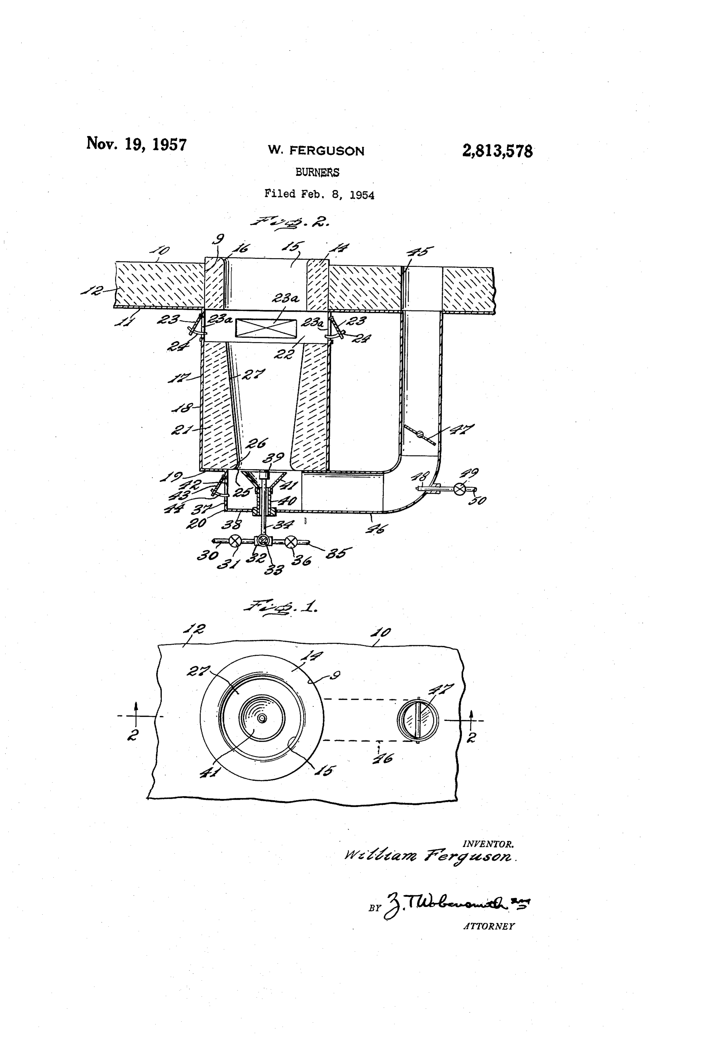
Fig. 2 is a vertical sectional view taken approximately which a duct 46 isextends
Page 1drawing sheetscan →
Page 2scan →
United States Patent Office 2,813,578 Patented Nov. 19, 1957
The upper face of the muffle block 4 extends a short distance above the upper surface of the floor 10 and 2,813,578 the lower face of the muffle block 14 is approximately on BURNERS the same level as the lower face of the floor plate 11. The muffle block 14 has a cylindrical opening 15 there
William Ferguson, Philadelphia, Pa., assignor to National through with a flare 16 at the upper end thereof. Airoil Burner Company, Incorporated, Philadelphia, Axially disposed below the muffle block 14, a burner Pa., a corporation of Delaware block housing 17 is provided, preferably of metal plate Application February 8, 1954, Serial No. 408,649 and having a vertical wall 18 and a horizontal wall 19. O A burner housing 20 is provided below the housing 17 6 Claims. (Cl. 158-1) and in axial alinement therewith.
Within the block housing 17, a burner block 21 of refractory material, is provided, the burner block 21 terminating in spaced relation to the muffle block 14 to
This invention relates to burners and more particularly 15 provide to burners for heavy or residuum oils. a chamber 22. The vertical length of the block In modern oil refinery practice, upfired furnaces are the muffle block about 2 is preferably two and one half times that of 14. The wall 18, at a location above frequently employed for furnaces, stills, heaters and the upper face of the burner block 21, is provided with similar separately fired devices. No substantial difficul a plurality ties have been encountered in the use of gas or light 20 are adaptedof topivotally mounted air inlet doors 23, which oils as fuel. Upon attempting to burn heavy or residuum quadrants 24 forbe determining adjusted as desired with respect to the amount of air de oils from the cracking processes, difficulties have been livered through air inlet openings 23a to the cham encountered because of coke deposition in the bore of ber 22.
refractory blocks used as part of the burner. The drip The burner block 21 has an interior bore shaped to ping of the heavy or residuum oils from the burner is 25 provide a venturi action and for this purpose has an objectionable both from the viewpoint of safety as well inlet section 25, a section of reduced diameter as at 26, as cleanliness of operation and this also has tended to and a frusto-conical section 27 of increasing diameter cause sticking of the air control mechanism. towards the chamber 22. The maximum diameter of In accordance with the present invention an improved the burner is provided for heavy and residuum oils which is 30 15 insection 27 is slightly less than that of the opening the muffle block 14.
free from the objections heretofore encountered. A steam supply pipe 30 having a valve 31 therein is In accordance with the present invention, also, an im proved burner is provided in which the temperature is provided for supplying steam for atomization and is con nected by a coupling 32 having a burner control valve maintained at levels such that the heavy or residuum 33 therein to a burner supply pipe 34. A fuel pipe 35 oils are liquefied and vaporized so as to assist in the 35 is provided, for supplying heavy or residuum oil for com introduction and burning thereof. bustion, is connected to the coupling 32, and has a con In accordance with the present invention, also, an im proved burner for heavy and residuum oils is provided in trolThevalve 36 for controlling the flow therethrough. burner housing 20 has a vertical side wall 37 which a recirculation of hot furnace gases is employed and a horizontal for heating. end wall 38 through which the supply 40 pipe 34 extends.
In accordance with the present invention, also, an im At the inner end of the Supply pipe 34 an atomizing proved burner for heavy and residuum oils is provided burner in which a recirculation of hot gases is employed for bore inhead 39 is provided, in axial alinement with the the burner block 21 and is located at the en heating and in which the gases and the primary air for trance to that bore.
combustion are aspirated by the steam used for atomizing 45 The supply pipe 34 has mounted therearound, on a the oil and by the advance of the fuel. tubular holder 40, a frusto-conical flange 41 which may Other objects and advantageous features of the inven function as a collecting cup and the outer margin of tion will be apparent from the description and claims. which is in spaced relation to the inlet section 25 of the The nature and characteristic features of the inven tion will be more readily understood from the following 50 burner The block 2 to provide a restricted passageway.
side wall 37 of the housing 20 has one or more description, taken in connection with the accompanying air inlet openings 42, with air inlet doors 43 which are drawings forming part thereof, in which: adapted to be adjusted with respect to quadrants 44 for Figure 1 is a top plan view of a furnace floor having determining the amount of air delivered to the interior a burner in accordance with the invention mounted of the housing 20.
therebelow; and 55
Fig. 2 is a vertical sectional view taken approximately which a duct 46 isextends
The floor 10 provided with an opening 45 from to and in communication with on the line 2-2 of Fig. 1.
It should, of course, be understood that the description 47 is preferably provided in 20.
the interior of the housing the
An adjustable damper duct 46 for controlling and drawings herein are illustrative merely, and that various modifications and changes may be made in the 60 the flow of gases therethrough. If it is desired to circu late more gases than would be aspirated or for circula structure disclosed without departing from the spirit of tion of hot gases without operating the burner to pre the invention. heat the blocks 4 and 21 a steam jet 48 may be provided Like numerals eral views.
refer to like parts throughout the sev in the duct 46. A control valve 49 is provided in the
Referring now more particularly to the drawings, a steam The supply line 50.
mode of operation will now be pointed out.
fragmentary portion of a furnace floor 10 is illustrated, of the character employed in stills, heaters and the like theFuel under pressure delivered through the pipe 35 to in refineries and other process industries, comprising a by the steamhead burner 39 is atomized and delivered therefrom horizontal metal plate 11 with a horizontal refractory fuel and steamdelivered through the pipe 30. The atomized delivered from the burner head 39, in its lining 12 thereon. - 70
The floor 10 is provided with an opening 9 within passage through the burner block 21, is subjected to heat therefrom so that the low hydrocarbon volatiles in the which a muffle block 14 of refractory material is mounted. oil are gasified, the atomizing steam is Superheated, and 3 the heavier fractions in the atomized fuel are heated to tory heat reflecting burner block spaced below said floor a high temperature approaching or exceeding vaporiza having a vertically disposed venturi openings therethrough, tion, which combined with the air in the recirculated a muffle block in said floor in spaced relation to said gases causes combustion to be rapidly initiated to insure burner block and having an opening therethrough alined combustion while the oil particles are in suspension. with said venturi opening and in communication with the As the combustible and burning gaseous material passes interior of the furnace, the length of said venturi opening from the bore of the burner block 21 through the chamber being a plurality of times the length of said muffle block 22 and into the opening 5 in the muffle block 14, Sufi opening, variable air inlet openings below said floor in cient secondary air is drawn in through the openings 23a communication with the space between said blocks, an at the air doors 23 to continue and complete the com 10 atomizing fuel burner discharge head disposed at the bustion of the combustible constituents. lower end of said burner block opening and discharging The aspirating effect of the fuel and steam is effective, upwardly therethrough, fluid connections connected to if desired, for drawing air through the openings 42 at said burner head for supplying atomizing fluid and oil the inlet doors 43. cracking residuums to said burner head, a member at the Under normal operating conditions there is present at 15 inlet end of said burner block opening and extending in and above the floor. 10 gaseous material having a pre spaced relation to said burner block opening for restrict ponderance of carbon dioxide with some free air con ing the inlet end of said burner block opening, a fluid taining oxygen. The average operating temperature at connection in spaced relation to the muffle block and ex this point, depending on operating conditions and furnace 20 tending from the interior of the floor of the furnace to design is from 1000 F. to 2200 F., and the carbon di the inlet end of the restricted opening for the delivery oxide content is from 5 to 13%. of hot gases from the furnace to said burner block open The aspirating effect of the fuel and steam from the ing for admixture with and heating of said residuums burner head 39, or the steam from the steam jet 48, and for heating said burner block, and a member carried or both, is effective for drawing hot furnace gases through 25 by said fluid connection having a variable air inlet open the opening 45 and the duct 45, as controlled by the ing for controlling the delivery of air for admixture with damper 47, and into the interior of the housing 20 where said hot gases, said atomizing fluid aspirating the air they mix with and temper the air drawn in at the doors to the space between said blocks and the hot gases to 43, contact and heat the flange 43 and then pass into said burner block opening.
the burner block opening where they aid in heating that 4. Apparatus for burning heavy oil cracking residuums block and the fuel and steam passing through the bore 30 comprising a furnace having a horizontal floor, a refrac of the block 2. tory fuel heating burner block spaced below said floor Any fuel initially collected in the flange 41, at start having a vertically disposed venturi opening therethrough, ing, is quickly vaporized and drawn upwardly for com a muffle block in said floor in spaced relation to said bustion. burner block and having a vertical opening therethrough The arrangement and operation heretofore described alined with said venturi opening and in direct communi has been found in practice to be very effective for pre cation with the interior of the furnace, said burner block venting coke deposits on the blocks 21 and 4 and also and its opening being of greater length than said muffle to prevent any dripping of the oil. block and its opening, variable air inlet openings below claim: said floor in communication with the space between said 1. Apparatus for burning heavy oil cracking residuums 40 blocks, an atomizing fuel burner discharge head disposed comprising a furnace having a horizontal floor, a refrac at the inlet end of said burner block opening and dis tory heat transferring burner block spaced below said charging inwardly therethrough, fluid connections con floor having a venturi opening therethrough, a muffle nected to said burner head for supplying atomizing fluid block in said floor in Spaced relation to said burner block and oil cracking residuums to said burner head, a mem and having an opening therethrough alined with said ber at the inlet end of said burner block opening burner block opening and in communication with the in and extending in spaced relation to said burner block terior of the furnace, said venturi opening being of a opening for restricting the inlet end of said burner greater length than said muffle block opening, variable block opening, said last member being alined with said air inlet openings below said floor in communication openings, a fluid connection in spaced relation to with the space between said blocks, an atomizing fuel 50 said muffle block and extending from the interior of burner discharge head disposed at the inlet end of said the floor of the furnace to the inlet end of the burner block opening and discharging upwardly there restricted opening for the delivery of hot gases from through, fluid connections connected to said burner head the furnace to said burner block opening for admixture for Supplying atomizing fluid and oil cracking residuums 55 with and heating of said residuums and for heating said to said burner head, a member at the inlet end of said burner block, and a member carried by said fluid con burner block opening and extending in spaced relation to nection having a variable air inlet opening for controlling Said burner block opening for restricting the inlet end the delivery of air for admixture with said hot gases said of Said burner block opening, a fluid connection from the atomizing fluid aspirating the air through said air inlet openings and the hot gases to said burner block open interior of the floor of said furnace and in spaced relation 60 ing to Said muffle block, said connection extending to the and through said burner block. inlet end of said burner block opening for the delivery 5. Apparatus for burning heavy oil cracking residuums of hot gases from the floor of the furnace to said burner comprising a furnace having a longitudinal floor, a burner block opening for admixture with and heating of said construction for said furnace below the floor of the residuums and for heating said burner block, and a 65 furnace comprising a muffle block disposed in the furnace member carried by said fluid connection having a vari floor and having a vertical opening therethrough, a able air inlet opening for controlling the delivery of air housing extending downwardly from the floor, a refractory for admixture with said hot gases, said atomizing fluid heat transferring burner block mounted in and supported aspirating the air through said inlet openings and the hot by said housing and spaced downwardly from said muffle gases to said burner block opening. 70 block, Said burner block having a vertically extending 2. A burner construction as defined in claim 1 in which venturi opening therethrough axially alined with said a steam jet is provided in the fluid connection for addi muffle block opening, the length of said burner block tionally inducing the flow of hot gases therethrough. opening being a plurality of times the length of said 3. Apparatus for burning heavy oil cracking residuums muffle block opening, the space between said blocks pro comprising a furnace having a horizontal floor, a refrac 75 viding a chamber, variable air inlet openings in the hous 4 ing in communication with said chamber, a burner hous opening, variable air inlet openings in the housing in com ing disposed below said first mentioned housing and munication with said chamber, a burner housing disposed having a chamber therein in communication with the below said first mentioned housing and having a chamber inlet end of said burner block opening, a burner supply therein in communication with the inlet end of said burner pipe extending vertically through said burner housing block opening, a burner supply pipe extending vertically chamber, an atomizing burner head on the inner end through said burner housing chamber, an atomizing burn of said pipe and at the inlet end of said burner block er head on the inner end of said pipe and at the inlet opening and discharging upwardly therethrough, a mem and of said burner block opening in axial alinement with ber Surrounding said pipe and extending in spaced rela said burner block opening and discharging upwardly there tion to Said burner block opening and providing a re 0 through, a member surrounding said pipe and providing a striction at the inlet end of the burner block opening and restriction at the inlet end of the burner block opening and a receptacle for vaporization of fuel fallout, a variable air a receptacle for vaporization of fuel fallout, a variable air inlet opening in communication with the chamber in said inlet opening in communication with the chamber in said burner housing, fluid connections connected to said burner burner housing, fluid connections connected to said burner supply pipe for supplying atomizing fluid and oil cracking 15 supply pipe for supplying atomizing fluid and oil cracking residuums to said burner supply pipe, the atomizing fluid residuums to said burner supply pipe, a fluid connection from said burner atomizing said residuums, aspirating air in communication with the furnace chamber through the through said air inlet openings and aspirating the hot furnace floor and with the chamber in said burner housing gases to said burner housing and into said burner block, for the delivery thereto of hot gases from the furnace a fluid connection in spaced relation to said muffle block 20 chamber, and a member in said fluid connection for con and in communication with the interior of the furnace trolling the flow through said fluid connection, said atom chamber at its inlet end and with the chamber in said izing fluid aspirating the air through said inlet openings burner housing for the delivery thereto of hot gases from and the hot gases to and through said burner block the furnace chamber for admixture with and heating of 25 opening.
said residuums and heating of said burner block, and a steam jet in said fluid connection for additionally deliver References Cited in the file of this patent ing said gases from said furnace chamber to said burner UNITED STATES PATENTS housing chamber.
6. Apparatus for burning heavy oil cracking residuums 1,145,504 O'Neil ------------------ July 6, 1915 comprising a furnace having a horizontal floor, a burner 30 1,609,150 Breese ---------------- Nov. 30, 1926 construction for said furnace disposed below the floor 1,684,991 Inglis ----------------- Sept. 18, 1928 of the furnace comprising a muffle block disposed in the 1,790,870 Mantle et al. ------------ Feb. 3, 1931 furnace floor and having a vertical opening therethrough, 1,891,877 Falkenwalde ------------ Dec. 20, 1932 a housing extending vertically downwardly from the 2,050,577 Littleton -------------- Aug. 11, 1936 floor, a refractory heat transferring burner block mounted 35 2,333,531 Luty ------------------ July 13, 1937 in said housing and spaced downwardly from said muffle Ferguson ---------------- Nov. 2, 1942 block, said burner block having a vertically extending 2,512,319 Ferguson -------------- June 20, 1950 venturi opening therethrough axially alined with said 2,688,360 Haynes et al. ------------ Sept. 7, 1954 muffle block opening, the space between said blocks pro 40 2,701,608 Johnson ---------------- Feb. 8, 1955 viding a chamber, the length of said burner block opening FOREIGN PATENTS being a plurality of times the length of said muffle block 523,871 Great Britain ------------ July 24, 1940
Provenance
- Collection
- Patents citing this work
- Pages
- 4
- Method
- pdftotext (the PDF's own text layer) + pdftoppm 300dpi page scans
- Patent office record
- patents.google.com →
- Source
- Google Patents citing-documents table
- Assignee
- Nat Airoil Burner Company Inc
- Published
- 1957-11-19
- Transcribed from
- patentimages.storage.googleapis.com →